
11. IO Settings
You can allocate IO signals,and configure project switch settings and project output settings.
11.1 IO Allocation
The Software supports setting IO types, trigger types, output types, and filter time.
IO
All IO lines are supported by the camera.
IO Type
Select Trigger, SolutionSwitch, or Output.
The IO settings vary with different device models.
● SC3000 Series Cameras: It has the following 8 IO lines: 2 inputs, 3 outputs, and 3 bidirectional configurable inputs/outputs. Line 0/1 can be set to Trigger or SolutionSwitch; Line 2/3/4 can be set to Trigger, SolutionSwitch, or Output; Line 5/6/7 can be set to Output.
● SC2000E(Mini) Series Cameras: It has 4 I/O lines of both inputs and outputs, which can be set to Trigger, SolutionSwitch, or Output. The IO types of Line 0/1 or Line2/3 are associated, meaning their settings are synchronized. For example,if you set Line0 to SolutionSwitch or Output, Line1 will be SolutionSwitch or Output; if you set Line0 to Trigger, Line1 will be SolutionSwitch.
● SC2000E Series Cameras: It has 4 I/O lines: 1 input, 1 output, 2 bidirectional configurable inputs/outputs. Line 0/1 can be set to both input and output, and their IO type can be set to Trigger, SolutionSwitch, or Output. Line2 can be set to input, andLine3 can be set to output.
● SC3000X, SC5000, and SC7000Pro Series Cameras: totally 6 IOs, including 3 inputs and 3 outputs. Line 0/1/2 can be set to Trigger or SolutionSwitch, while Line 3/4/5 can be set to Output.
Note
Only 1 IO can be set to Trigger. When one of the IOs is set to Trigger, other IOs cannot be set to Trigger.
Trigger Type
When the IO type is Trigger, set this parameter.
Output Type
Polarity of output signals.
Note
SC2000E(Mini) only supports NPN, and SC3030 only supports PNP
11.2 Project Switch Settings
If you create multiple projects and set the auto-switch mode of a project to TriggerIO, this project will be selected as the running project when the signal meets the requirements of the switch trigger source and is received within the configured IO synchronization time.
Before You Start
Select TriggerIO as the mode of project auto-switch settings.
Steps
1. Select a switch trigger source.
● The switch trigger source name is represented by a sequence of numbers or
characters (from right to left) that correspond to the line numbers of the device.
● The number of characters consisting the switch trigger source name is the same with
the line number of IO signals. Each number or character can be either 0, 1, or *.
Note
○ If the IO type is SolutionSwitch and the trigger type is set to LevelHigh, the number is 1.
○ If the IO type is SolutionSwitch and the trigger type is set to LevelLow, the number is 0.
○ If the IO type is Trigger or Output, the number is *.
2. On the right column, select a project.
3. Set IO Sync Time.
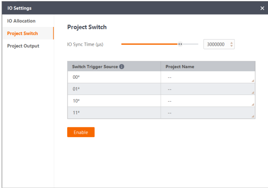
Figure 11-1 Project Switch Settings
Example
If an SC3000 series camera's project trigger source is *101* and the IO sync time is 3, we can get the conclusion that the IO type of Line0 is Trigger, the IO type of Line4 is Output, and the IO types of Line1 to Line3 are all set to SolutionSwitch. To automatically switch to this project, the signal LevelHigh of Line1 to Line3 should be sent to the camera within 3 seconds.
11.3 Project Output Settings
You can view all devices' IO outputs and configure the relevant parameters to ensure that the devices output signals as required.
Output Condition
Subscribe to module statuses of different tools to determine the type of IO output.
Output Hold
The location of IO output signals and the electronic level.
Disable
Set the duration time and delay time to control IO output signals.
TriggerReset
When the device receives a trigger signal, the IO output signal is set to levellow. Then, based on the subscribed module results and the set output type, the IO output signal is set to the corresponding electronic level. The level persists until the next trigger signal is received.
ReverseReset
If the module status subscribed by device output is opposite to the configured output type,the IO output signal is set to levellow until a model status matching the output type is received.
Note
Output Hold should be supported by the device.
Duration Time
The duration of the output signal remaining at a specific electronic level.
Delay Time
The device outputs signals after the configured delay time ends.
Valid Electrical Level
Normally Close means valid levelhigh, while Normally Open means valid levellow.
Out Type
When the device meets the option you select, the IO signals will be output. Note SC2000E(Mini) and SC2000E series cameras do not support EposureOutPut.
Cache Enable
If enabled,the subsequent output signal will be cached while the previous signal is still
being output. Once the previous output ends, the cached signal will be automatically
output. No more than 3 signals can be cached.
Note
This parameter varies with different series of devices.
● SC2000E(Mini), SC2000E, and SC3000X series do not support this parameter.
● SC3000 series cache no more than 3 output signals.
● SC5000 and SC7000Pro cache not more than 16 output signals.