
13. Tool Introduction
eVarious types of tools can be added to cameras to perform visual detection.
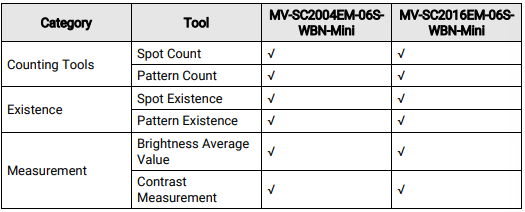
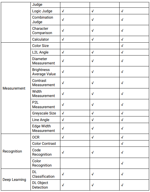
Tools Supported by SC2000E(Mini) Series Cameras
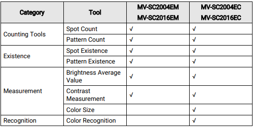
Tools Supported by SC2000E Series Cameras
Table 13-1
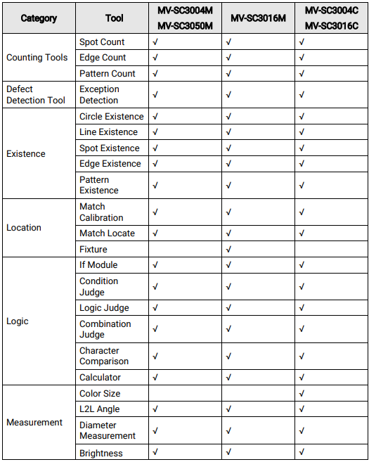
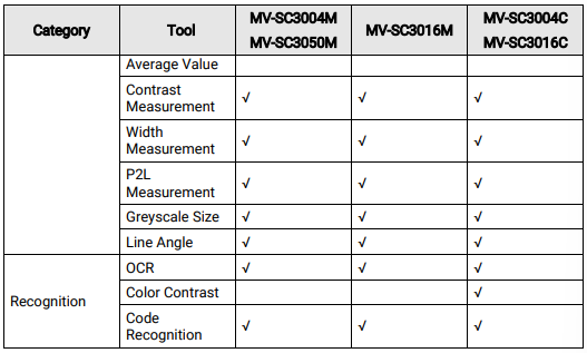
Tools Supported by SC3000 Series Cameras
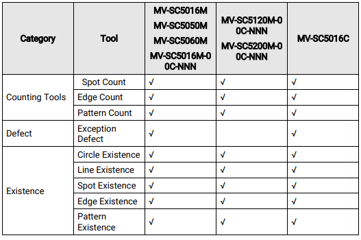
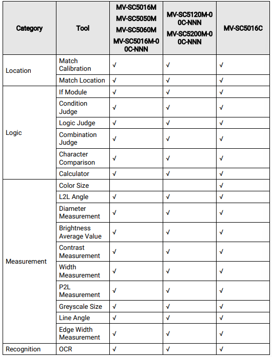
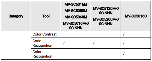
Tools Supported by SC5000 Series Cameras
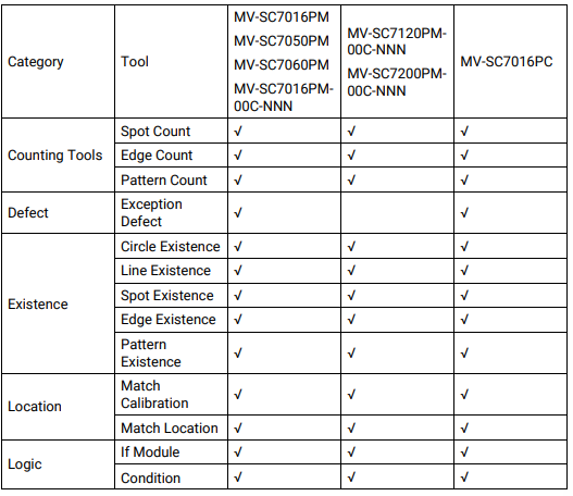
Tools Supported by SC7000 Pro Series Cameras
 13.1 Measuring Tool
Measuring tools analyzes images via measurement.
13.1.1 Color Size
The Color Size tool calculates the area size with qualified colors in the detection area
Before You Start
● Make sure that the connected camera is the color camera and the Greyscale Image Output function is disabled.
● Make sure that you have configured the camera parameters and base image, and added the Color Size tool.
● This function is available only when the Greyscale Image Output function of color device is disabled. Only color camera supports this tool.
● If you enable the Greyscale Image Output function for a color camera, the color size tool can still be configured but the output result will be NG.
Steps
1. Set the Detection Area as needed. It it set to analyze the whole base image by default.
Click  or
or  or
or  to draw on the base image; click to set the whole base image
as the detection area.
Note
Refer to How to draw an ROI? for ROI drawing details.
2. Optional: If you need to shield areas in the detection area, click Edit on the right of Shield Area, and then click to draw polygons on the base image.
3. Optional: You can enable or disable Independent Fixture as needed. When enabled, target offset can be adjusted according to the parameter settings of the chosen fixture configuration. This function is enabled by default and automatically subscribes to the fixture configuration of the base image.
Make sure you have enabled Fixture when configuring the base image. Refer to Configure Base Image for details.
4. Set recognition-related parameters.
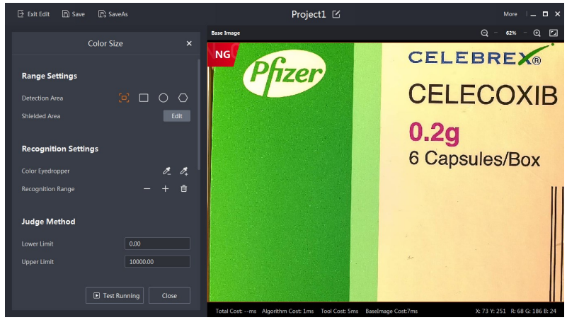
Figure 13-1 Recognition-Related Parameters
Color Eyedropper
Set the color value range to be recognized or not need to be recognized. Click and  move the cursor on the base image to select the area to be recognized. The pixels with the same color value will turn to green. You can click
  and select an area that does not need to be recognized.
Recognition Range
Click  and move the cursor on the area defined by the color dropper to enlarge or narrow down the to-be-recognized area.
Note
Click  to clear the recognition range you set.
5. In Judge Method, set Upper Limit and Lower Limit. If the detection result is within the configured range, the result is OK. Otherwise, the result is NG.
Note
The Judge Method parameters vary according to the camera type. For some cameras, the Judge Method parameter is the similarity range, which is from 0% to 200%. If the value cannot satisfy your need, you can switch 200% to 900%. The maximum similarity range is 900%. If the actual value is higher than 900%, the camera will respond based on 900%.
6. Optional: Set extra parameters in Extend Parameter if the result is not what you have expected.
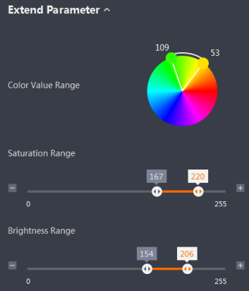
Figure 13-2 Extend Parameter
Color Value Range
The color value of the to-be recognized area. It will change in a real time when you edit the parameters in recognition settings.
Saturation Range
Only pixels with a saturation in this range will be recognized.
Brightness Range
Only pixels with a brightness in this range will be recognized.
7. Click  Test Running to test the detection according to settings.
Note
Click  Stop Running to stop the test.
13.1.2 L2L Angle
Find straight lines in two ROIs and calculate the angle between the two straight lines. You can configure range settings, recognition settings, judge method, and extend parameter for the tool.
● Range Settings: You can set area-related parameters.
○ Detection Area: Click  and click on a position on the two lines respectively.
Note
Click  beside the Detection Area to display the tutorial video on the top left of the live view image.
○ Shielded Area: The shielded area will not be analyzed by the tool. Click Edit →  and
and
draw the shielded area on the base image in the live view image.
○ Independent Fixture: When enabled, target offset can be adjusted according to the parameter settings of the chosen fixture configuration. This function is enabled by default and automatically subscribes to the fixture configuration of the base image.
Note
Make sure you have enabled Fixture when configuring the base image. Refer to Configure Base Image for details.
● In Recognition Settings, you can set recognition-related parameters. Line 1/2 Sensitivity Adjustment: Adjust the sensitivity when measuring line 1 and line 2. When adjusting the parameter, the result will be displayed on the map located on the top right. Red indicates the sensitivity range.
● In Judge Method, set the Upper Limit and the Lower Limit. If the detection result is within the range you set, the tool will output OK, otherwise the tool will output NG.
Note
For some cameras, the Similarity Range will be displayed here. When the similarity between the detected angle and that of the base image is within the range, the result will be OK, or the result will be NG. By default, the similarity range is from 0% to 200%. If the value cannot satisfy your need, you can switch 200% to 900%. The maximum similarity range is 900%. If the actual value is higher than 900%, the camera will respond based on 900%.
● In Extend Parameter, you can set extra parameters for line1 and line 2 if the result is not what you have expected.
○ Straightness Accuracy: the minimum ratio of the number of points used to make up lines to the total number of points. When a line's line rate is higher than the configured rate, it will be recognized as a line, otherwise it will not. The more points selected, the more accurate the line will be.
○ Edge Polarity:It represents the excessive change of color.
› Black to White: The tool recognizes edges from area with higher grey scale to the area with lower grey scale.
› White to Black: The tool recognizes edges from the area with lower grey scale to the area with higher grey scale.
› All: The tool recognizes edges from area with higher grey scale to area with lower grey scale and from area with lower grey scale to area with higher grey scale.
○ Edge Type: You can select "The Best", "The First", "The Last", and "Manual".
› The Best: The tool will find the most suitable points to make up lines.
› The First: The tool will find the points nearest to the start point to make up lines.
› The Last: The tool will find the point nearest to the end points to make up lines.
› Manual: Based on the green lines in the greyscale layout map, you can manually select points to make up lines.
Note
If the edge type is set to "Manual", the edge polarity is set to "All" automatically and it cannot be changed.
After setting the above parameters, you can go to Output → Tool Results to set which data to transmit to the communication tool by the tool. The data can be transmitted are as follows: module status, point measure intersection point angle, point measure intersection point angle X, point measure intersection point angle Y, point measure distance, point measure line 1 start point X, point measure line 1 start point Y, point measure line 1 end point X, point measure line 1 end point Y, point measure line 1 angle, point measure line 2 start point X, point measure line 2 start point Y, point measure line 2 end point X, point measure line 2 end point Y, point measure line 2 angle, result similarity, detection area center X, detection area center Y, detection area width, detection area height, detection area angle, result quantity, and base value.
13.1.3 Diameter Measurement
In the detection area range, measure the diameter of the circle. You can configure range settings, recognition settings, judge method, and extend parameter for the tool.
● Range Settings: You can set area-related parameters.
○ Detection Area: Click  and click the base image to draw a circle on the base image.
Note
Click  beside the Detection Area to display the tutorial video on the top left of the live view image.
○ Shielded Area: The shielded area will not be analyzed by the tool. Click Edit → and draw the shielded area on the base image in the live view image.
○ Independent Fixture: When enabled, target offset can be adjusted according to the parameter settings of the chosen fixture configuration. This function is enabled by default and automatically subscribes to the fixture configuration of the base image.
Note
Make sure you have enabled Fixture when configuring the base image. Refer to Configure Base Image for details.
● In Recognition Settings, you can set recognition-related parameters. Sensitivity Adjustment: Adjust the sensitivity when measuring the circle. When adjusting the parameter, the result will be displayed on the map located on the top right. Red indicates the sensitivity range.
● In Judge Method, set the Upper Limit and the Lower Limit. If the detection result is within the range you set, the tool will output OK, otherwise the tool will output NG.
Note
For some cameras, the Similarity Range will be displayed here. When the similarity between the detected angle and that of the base image is within the range, the result will be OK, or the result will be NG. By default, the similarity range is from 0% to 200%. If the value cannot satisfy your need, you can switch 200% to 900%. The maximum similarity range is 900%. If the actual value is higher than 900%, the camera will respond based on 900%
● In Extend Parameter, you can set extra parameters for line1 and line 2 if the result is not what you have expected.
○ Circle Rate: The minimum ratio of the number of points used to make up circles to the total number of points. When a circle's circle rate is higher than the configured rate, it will be recognized as a circle, otherwise it will not. The more points selected, the more accurate the circle will be.
○ Edge Polarity:It represents the excessive change of color.
› Black to White: The tool recognizes edges from area with higher grey scale to the area with lower grey scale.
› White to Black: The tool recognizes edges from the area with lower grey scale to the area with higher grey scale.
› All: The tool recognizes edges from area with higher grey scale to area with lower grey scale and from area with lower grey scale to area with higher grey scale.
○ Edge Type: You can select "The Best", "The Biggest", "The Smallest", or "Manual".
› The Best: The tool will find the most suitable points to make up lines.
› The Biggest: The tool will find the points that are the most distant from the center to make up circles.
› The Smallest: The tool will find the points nearest to the center to make up circles.
› Manual: Based on the green lines in the greyscale layout map, you can manually select points to make up circles.
Note
If the edge type is set to "Manual", the edge polarity is set to "All" automatically and it cannot be changed.
After setting the above parameters, you can go to Output → Tool Results to set which data to transmit to the communication tool by the tool. The data can be transmitted are as follows: module status, detection area center X, detection area center Y, detection area width, detection area height, detection area angle, circle diameter, circle center X, circle center Y, circle radius, result quantity, and base value.
13.1.4 Brightness Analysis
The Brightness Average Value tool can measure the brightness of an ROI and then calculate the mean value.
Before You Start
Make sure that you have configured the camera parameters and base image, and added the Brightness Average Value tool.
Steps
1. Set the Detection Area as needed. It it set to analyze the whole base image by default.
Click  or
or  or
or  to draw on the base image, the position and size of the area can be adjusted manually; click to set the whole base image as the detection area.
Note
Refer to How to draw an ROI? for ROI drawing details
2. Optional: If you need to shield areas in the detection area, click Edit on the right of Shielded Area, and then click  to draw polygons on the base image.
3. Optional: You can enable or disable Independent Fixture as needed. When enabled, target offset can be adjusted according to the parameter settings of the chosen fixture configuration. This function is enabled by default and automatically subscribes to the fixture configuration of the base image. Make sure you have enabled Fixture when configuring the base image. Refer to Configure Base Image for details.
4. In Judge Method, set Upper Limit and Lower Limit. If the detection result is within the configured range, the result is OK. Otherwise, the result is NG.
Note
The Judge Method parameters vary according to the camera type. For some cameras, the Judge Method parameter is the similarity range, which is from 0% to 200%. If the value cannot satisfy your need, you can switch 200% to 900%. The maximum similarity range is 900%. If the actual value is higher than 900%, the camera will respond based on 900%.
5. Click  Test Running to test the detection according to settings.
Note
Click  Stop Running to stop the test.
13.1.5 Contrast Measurement
The Contrast Measurement tool can measure the contrast of the detection area.
Before You Start
Make sure that you have configured the camera parameters and base image, and added the Contrast Measurement tool.
Contrast is a relative value, representing the ratio of brightest to the darkest of the detection area.
Steps
1. Set the Detection Area as needed. It it set to analyze the whole base image by default.
Click or or to draw on the base image; click  to set the whole base image
as the detection area.
Note
Refer to How to draw an ROI? for ROI drawing details.
2. Optional: If you need to shield areas in the detection area, click Edit on the right of Shielded Area, and then click to draw polygons on the base image.
3. Optional: You can enable or disable Independent Fixture as needed. When enabled, target offset can be adjusted according to the parameter settings of the chosen fixture configuration. This function is enabled by default and automatically subscribes to the fixture configuration of the base image.
Make sure you have enabled Fixture when configuring the base image. Refer to Configure Base Image for details.
4. In Judge Method, set Upper Limit and Lower Limit. If the detection result is within the configured range, the result is OK. Otherwise, the result is NG.
Note
The Judge Method parameters vary according to the camera type. For some cameras, the Judge Method parameter is the similarity range, which is from 0% to 200%. If the value cannot satisfy your need, you can switch 200% to 900%. The maximum similarity range is 900%. If the actual value is higher than 900%, the camera will respond based on 900%.
5. Click Test Running to test the detection according to settings.
Note
Click Stop Running to stop the test.
13.1.6 Width Measurement
The Width Measurement tool can detect two edges in the detection area and measure the perpendicular distance between the two edges.
The parameters of the tool are divided into four categories: range settings, recognition settings, judge method, and extend parameter.
● Range settings determine the detection area:
Detection Area
Click  and click on the two endpoints on the base image to measure the distance between the two edges.
Note
Click  to show animated instructions on drawing ROI.
Shielded Area
Specify the shielded area within the detection area. The shielded area will not be analyzed. Click Edit and then click  to draw a polygon on then base image.
Independent Fixture
When enabled, target offset can be adjusted according to the parameter settings of the chosen fixture configuration. This function is enabled by default and automatically subscribes to the fixture configuration of the base image.
Note
Make sure you have enabled Fixture when configuring the base image. Refer to Configure Base Image for details.
● Recognition settings determine the pattern recognition conditions: Sensitivity Adjustment Adjust the sensitivity of edge detection. The grayscale graph in the upper-right corner shows the current effect, and the red area is the sensitivity range.
● In Judge Method, set the Upper Limit and the Lower Limit. If the detection result is within the range you set, the tool will output OK, otherwise the tool will output NG.
Note
For some cameras, the Similarity Range will be displayed here. When the similarity between the detected angle and that of the base image is within the range, the result will be OK, or the result will be NG. By default, the similarity range is from 0% to 200%. If the value cannot satisfy your need, you can switch 200% to 900%. The maximum similarity range is 900%. If the actual value is higher than 900%, the camera will respond based on 900%.
● If the parameter settings above cannot achieve the expected outcome, you can adjust the Extend Paramete
Polarity
Color transition direction. Edge polarity is related to the arrow's direction of the ROI
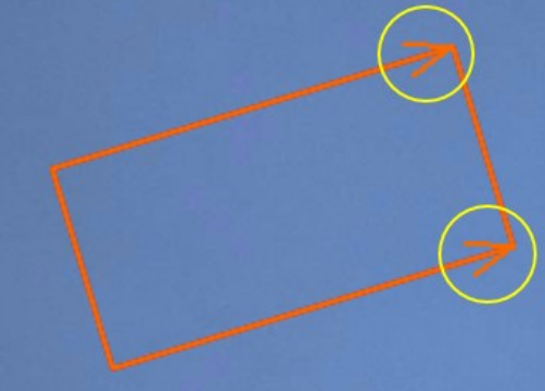
Figure 13-3 Arrow Directions
Black To White
Only detect the edge formed by low grayscale to high grayscale.
White To Black
Only detect the edge formed by high grayscale to low grayscale.
All
Detect any type of edge.
Width Extraction
The Widest
Only detect the edge pair with the longest distance.
The Narrowest
Only detect the edge pair with the shortest distance.
Manual
Drag the green line in the grayscale graph in the upper-right corner to select the set of edge points and fit the edge pair.
Note
If you select Manual, the polarity will be set to All and cannot be changed. After setting the above parameters, you can go to Output → Tool Results to set which data to transmit to the communication tool. The output data items include: module status, detection area center X/Y, detection area width/height/angle, line start point X/Y, line end point X/Y, result similarity, line 0 start point X/Y, line 0 end point X/Y, line 0 angle, line 1 start point X/Y, line 1 end point X/Y, line 1 angle, pixel edge spacing, and base value.
13.1.7 P2L Measurement
The P2L Measurement tool can detect edges and lines, and then measure the perpendicular distance between a point (on a line/edge) and a line/edge.
Before You Start
Make sure that you have configured the camera parameters and base image, and added the P2L Measurement tool.
Steps
1. Click  and click on the base image to determine the point and then click twice to
draw on the line so as to measure the distance between the point and the line.
Note
Click  to show animated instructions on drawing ROI.
2. Optional: If you need to shield areas in the detection area, click Edit on the right of
Shielded Area, and then click  to draw polygons on the base image.
Note
Refer to How to draw an ROI? for ROI drawing details.
3. Optional: You can enable or disable Independent Fixture as needed. When enabled, target offset can be adjusted according to the parameter settings of the chosen fixture configuration. This function is enabled by default and automatically subscribes to the fixture configuration of the base image. Make sure you have enabled Fixture when configuring the base image. Refer to Configure Base Image for details.
4. Set the pattern recognition conditions in Recognition Settings.
Line Sensitivity Adjustment
Adjust the sensitivity of line detection. The grayscale graph in the upper-right corner shows the current effect, and the red area is the sensitivity range.
Point Sensitivity Adjustment
Adjust the sensitivity of point detection. The grayscale graph in the upper-right corner shows the current effect, and the red area is the sensitivity range.
5. In Judge Method, set the Upper Limit and the Lower Limit. If the detection result is within the configured range, the result is OK. Otherwise, the result is NG.
Note
The Judge Method parameters vary according to the camera type. For some cameras, theJudge Method parameter is the similarity range, which is from 0% to 200%. If the value cannot satisfy your need, you can switch 200% to 900%. The maximum similarity range is 900%. If the actual value is higher than 900%, the camera will respond based on 900%.
6. Set extra parameters in Extend Parameter if the result is not what you have expected.
● Line Parameters:
Line Rate
You can set the minimum value of the ratio of the fitting points to the total number of points. When the straightness of the detected line exceeds this value, it is judged as a straight line. Otherwise, it is not judged as a straight line.
Edge Polarity
Color transition direction. Edge polarity is related to the arrow's direction of the ROI.

Figure 13-4 Arrow Directions
Black To White
Only detect the edge formed by low grayscale to high grayscale.
White To Black
Only detect the edge formed by high grayscale to low grayscale.
All
Detect any type of edge.
Edge Type
The Best
Only detect edge points with the largest gradient threshold and fit them into a line.
The First
Only detect edge points that are the nearest to the detection start point and fit them into a line.
The Last
Only detect edge points that are the nearest to the detection end point and fit them into a line.
Manual
Drag the green line in the grayscale graph in the upper-right corner to select the set of edge points and fit them into a line.
Note
If you select Manual, the polarity will be set to All and cannot be changed.
● Point Parameters:
Edge Polarity
Refer to the descriptions in Line Parameters.
7. Click  Test Running to test the detection according to settings.
Note
Click  Stop Running to stop the test.
13.1.8 Greyscale Size
The Greyscale Size tool can measure the area of pixels with greyscale value that is within the range you set.
Before You Start
Make sure that you have configured the camera parameters and base image, and added the Greyscale Size tool.
Steps
1. Set the Detection Area as needed. It it set to analyze the whole base image by default.
Click or or to draw on the base image, the position and size of the area can be adjusted manually; click to set the whole base image as the detection area.
Note
Refer to How to draw an ROI? for ROI drawing details.
2. Optional: If you need to shield areas in the detection area, click Edit on the right of Shielded Area, and then click to draw polygons on the base image.
3. Optional: You can enable or disable Independent Fixture as needed. When enabled, target offset can be adjusted according to the parameter settings of the chosen fixture configuration. This function is enabled by default and automatically subscribes to the fixture configuration of the base image. Make sure you have enabled Fixture when configuring the base image. Refer to Configure Base Image for details.
4. Set the pattern recognition conditions in Recognition Settings.
Greyscale Threshold
Set the valid greyscale value range. Qualified area will be marked in green.
Reverse Range
When enabled, the unqualified area will be marked in green. It is used to measure the area that is not within the valid greyscale range.
5. In Judge Method, set the Upper Limit and the Lower Limit. If the detection result is within the configured range, the result is OK. Otherwise, the result is NG.
Note
The Judge Method parameters vary according to the camera type. For some cameras, the Judge Method parameter is the similarity range, which is from 0% to 200%. If the value cannot satisfy your need, you can switch 200% to 900%. The maximum similarity range is 900%. If the actual value is higher than 900%, the camera will respond based on 900%.
6. Optional: Set extra parameters in Extend Parameter if the result is not what you have expected.
Area Range
Set the recognition area size. Unit: pixel.
7. Click  Test Running to test the detection according to settings.
Note
Click  Stop Running to stop the test.
13.1.9 Line Angle
The Line Angle tool can measure the angle between a line and the X-axis. The parameters of the tool are divided into four categories: range settings, recognition settings, judge method, and extend parameter.
● Range settings determine the detection area:
Detection Area
Click  and click on two points on a line on the base image to get the starting point coordinates and intersection angle.
Note
○ Click  to show animated instructions on drawing ROI.
○ Click  on the top of the base image window to view notes about the coordinates image.
Shielded Area
Specify the shielded area within the detection area. The shielded area will not be analyzed. Click Edit and then click to  draw a polygon on the base image.
Independent Fixture
When enabled, target offset can be adjusted according to the parameter settings of the chosen fixture configuration. This function is enabled by default and automatically subscribes to the fixture configuration of the base image.
Note
Make sure you have enabled Fixture when configuring the base image. Refer to Configure Base Image for details
● Recognition settings determine the pattern recognition conditions:
Sensitivity
Adjust the sensitivity of edge detection. The grayscale graph in the upper-right corner shows the current effect, and the red area is the sensitivity range.
● In Judge Method, set the Upper Limit and the Lower Limit. If the detection result is within the range you set, the tool will output OK, otherwise the tool will output NG.
Note
For some cameras, the Similarity Range will be displayed here. When the similarity between the detected angle and that of the base image is within the range, the result will be OK, or the result will be NG.By default, the similarity range is from 0% to 200%. If the value cannot satisfy your need, you can switch 200% to 900%. The maximum similarity range is 900%. If the actual value is higher than 900%, the camera will respond based on 900%.
● If the parameter settings above cannot achieve the expected outcome, you can adjust
the Extend Parameter for the line.
Line Rate
You can set the minimum value of the ratio of the fitting points to the total number of
points. When the straightness of the detected line exceeds this value, it is judged as a
straight line. Otherwise, it is not judged as a straight line.
Edge Polarity
Color transition direction. Edge polarity is related to the arrow's direction of the ROI

Figure 13-5 Arrow Directions
Black To White
Only detect the edge formed by low grayscale to high grayscale.
White To Black
Only detect the edge formed by high grayscale to low grayscale.
All
Detect any type of edge.
Edge Type
The Best
Only detect edge points with the largest gradient threshold and fit them into a line.
The First
Only detect edge points that are the nearest to the detection start point and fit them into a line.
The Last
Only detect edge points that are the nearest to the detection end point and fit them into a line.
Manual
Drag the green line in the grayscale graph in the upper-right corner to select the set of edge points and fit them into a line.
Note
If you select Manual, the polarity will be set to All and cannot be changed.
After setting the above parameters, you can go to Output → Tool Results to set which
data to transmit to the communication tool.
The output data items include: module status, line start point X/Y, line end point X/Y, detection area center X/Y, detection area width/height/angle, result similarity, and base value.
13.1.10 Edge Width Measurement
The Edge Width Measurement tool measures the distance between two edges in an ROI.
Before You Start
Make sure that you have configured the camera parameters and base image, and have added the Edge Width Measurement tool.
Steps
1. Click  and then draw a detection area on the image.
Note
After drawing the detection area, a histogram will show on the top right of the image displaying the greyscale difference between adjacent pixels.
2. Click Edit to draw a shielded area in the detection area.
Note
See About ROI for details about drawing an ROI.
3. Optional: You can enable or disable Independent Fixture as needed. When enabled,
target offset can be adjusted according to the parameter settings of the chosen fixture
configuration. This function is enabled by default and automatically subscribes to the
fixture configuration of the base image.
Make sure you have enabled Fixture when configuring the base image. Refer to Configure Base Image for details.
4. Select a sensitivity for the tool.
5. Configure the Judge Method, including judge basis, range low, and range high.
6. Set the Extend Parameters.
Width
The width of the object.
| Parameter | Description |
| Brightness Mode | The reference for identifying an object. |
| Find Measure Mode | The method of measurement. |
The distance between two objects.
7. Click Test Running to test the tool.
13.2 Existence Tool
The existence tools are as follows: the circle-existence tool, line-existence tool, spot-existence tool, edge-existence tool, pattern-existence tool, and profile-existence tool.
13.2.1 Circle Existence
The circle-existence tool can find multiple points in a detection area and fit them into circles. It can also detect existing circles in the area.
The parameter settings for the circle-existence tool include range settings, recognition settings, judge method settings, and extend parameter settings.
● In Range Settings, you can set area-related parameters.
○ Detection Area: Click  , hover the cursor on the circle, and the click the mouse to display the recognized circle and its center coordinate.
Note
Click  beside Detection Area, and the animated tutorial will pop up in the upper-left corner of the live view panel.
○ Shielded Area: Here you can shield some areas for them not to be analyzed. Click Edit, and then click  to draw polygons on the base image.
○ Independent Fixture: When enabled, target offset can be adjusted according to the parameter settings of the chosen fixture configuration. This function is enabled by default and automatically subscribes to the fixture configuration of the base image
Note
› This function is enabled by default and automatically subscribes to the fixture configuration of the base image.
› Make sure you have enabled Fixture when configuring the base image. Refer to Configure Base Image for details.
● In Recognition Settings, you can set recognition-related parameters. ○ Sensitivity: the sensitivity of circle detection. When setting this parameter, the greyscale layout map in the upper-right corner of the live view panel will display the effect, and the red area represents the sensitivity range.
● In Judge Method, you can set parameters related to result judgment by selecting "Exist OK" or "Not Exist OK". For Not Exist OK, if there are no circles that meets the configured parameter requirements, the result will be "OK".
● In Extend Parameter, you can set extra parameters if the result is not what you have expected.
○ Circle Rate: the minimum ratio of the number of points used to make up circles to the total number of points. When a circle's circle rate is higher than the configured rate, it will be recognized as a circle, otherwise it will not. The more points selected, the more accurate the circle will be.
○ Edge Polarity: It represents the excessive change of color, defines the direction to look for the edges in a detection area. Here the center of the circle is the starting point, it stretches from the inside to the outside of the circle, and the edge is the line between two areas with different greyscales.
› Black to White: The tool recognizes edges from the area with higher greyscale to the area with lower greyscale.
› White to Black: The tool recognizes edges from the area with lower greyscale to the area with higher greyscale.
› All: The tool recognizes edges from the area with higher greyscale to the area with lower greyscale and from the area with lower greyscale to the area with higher greyscale.
○ Edge Type: You can select "The Best", "The Biggest", "The Smallest", or "Manual".
› The Best: The tool will find the most suitable points to make up circles.
› The Biggest: The tool will find the points that are the most distant from the center to make up circles.
› The Smallest: The tool will find the points nearest to the center to make up circles.
› Manual: Based on the green lines in the greyscale layout map, you can manually select points to make up circles.
Note
If the edge type is set to "Manual", the edge polarity is set to "All" automatically and it cannot be changed.
After setting the above parameters, you can go to Output → Tool Results to set which data to transmit to the communication tool by the circle-existence tool.
The data can be transmitted are as follows: module status, circle center X, circle center Y, circle radius, detection area center X, detection area center Y, detection area width, detection area height, and detection area angle.
13.2.2 Line Existence
The line-existence tool can find points with specific features to fit them into straight lines. The parameter settings for the line-existence tool include range settings, recognition settings, judge method settings, and extend parameter settings.
● In Range Settings, you can set area-related parameters.
○ Detection Area: Click  , and then click two different positions on the base image to draw a detection area.
Note
› On the top left of the live view window, click  next to Base Image to view descriptions of the coordinate axes.
› Click beside Detection Area, and the animated tutorial will pop up in the upper-left corner of the preview window.
○ Shielded Area: Here you can shield some areas for them not to be analyzed. Click Edit, and then click  to draw polygons on the base image.
○ Independent Fixture: When enabled, target offset can be adjusted according to the parameter settings of the chosen fixture configuration. This function is enabled by default and automatically subscribes to the fixture configuration of the base image.
Note
› This function is enabled by default and automatically subscribes to the fixture configuration of the base image.
› Make sure you have enabled Fixture when configuring the base image. Refer to Configure Base Image for details.
● In Recognition Settings, you can set recognition-related parameters.
○ Line Sensitivity Adjustment: Here you can adjust the sensitivity of line detection. When adjusting this parameter, the greyscale layout map in the upper-right corner of the preview window will display the effect of adjustment, and the red area represents the sensitivity range.
● In Judge Method, you can set the parameters related to result judgment by selecting Exist OK or .
● In Extend Parameter, you can set extra parameters if the result is not what you have expected.
○ Line Rate: the minimum ratio of the number of points used to make up lines to the total number of points. When a line's line rate is higher than the configured rate, it will be recognized as a line, otherwise it will not. The more points selected, the more accurate the line will be.
○ Edge Polarity:It represents the excessive change of color, and defines the direction to look for the edges in a detection area. Here the edge is the line between two areas with different greyscales.
› Black to White: The tool recognizes edges from the area with higher greyscale to the area with lower greyscale.
› White to Black: The tool recognizes edges from the area with lower greyscale to the area with higher greyscale.
› All: The tool recognizes edges from the area with higher greyscale to the area with lower greyscale and from the area with lower greyscale to the area with higher greyscale.
○ Edge Type: You can select "The Best", "The First", "The Last", and "Manual".
› The Best: The tool will find the most suitable points to make up lines.
› The First: The tool will find the points nearest to the start point to make up lines.
› The Last: The tool will find the point nearest to the end points to make up lines.
› Manual: Based on the green lines in the greyscale layout map, you can manually select points to make up lines.
Note
If the edge type is set to "Manual", the edge polarity is set to "All" automatically and it cannot be changed.
After setting the above parameters, you can go to Output → Tool Results to set which data to transmit to the communication tool by the circle-existence tool. The data can be transmitted are as follows: module status, line start point X, line start point Y, line end point X, line end point Y, line angle, detection area center X, detection area center Y, detection area width, detection area height, detection area angle.
13.2.3 Spot Existence
Spot Existence tool is used for analyzing whether there are areas with qualified greyscale in the analyzed area.
Before You Start
Make sure that you have configured the camera parameters and base image, and added the Spot Count tool.
Steps
1. Set the Detection Area as needed. It it set to analyze the whole base image by default. Click or
or  or
or  to draw on the base image, the position and size of the area can be adjusted manually; click
  to set the whole base image as the detection area.
Note
Refer to How to draw an ROI? for ROI drawing details.
2. Optional: If you need to shield areas in the detection area, click Edit on the right of Shield Area, and then click  to draw polygons on the base image.
3. Optional: Enable or disable Independent Fixture as needed. When enabled, target offset can be adjusted according to the parameter settings of the chosen fixture configuration.
Note
● This function is enabled by default and automatically subscribes to the fixture configuration of the base image.
● Make sure you have enabled Fixture when configuring the base image. Refer to Configure Base Image for details.
4. Set recognition-related parameters in Recognition Settings.
Greyscale Threshold
Set the greyscale range for detection area. The area with greyscale in the range will be recognized.
Reverse Range
The area with greyscale not in the range will be recognized.
5. Set the result judgment parameters in Judge Method.
Exist OK
The result is OK if the area, which meets the configured requirement is detected.
Reverse Range
The result is OK if the area, which meets the configured requirement is not detected.
6. Optional: Set extra parameters in Extend Parameter if the result is not what you have expected.
Area Range
Set the area of recognized area. The unit is pixel.
7. Click Test Running to test the detection according to settings.
Note
Click Stop Running to stop the test.
13.2.4 Edge Existence
The tool will detect edges with qualified sensitivity in the detection area.
You can configure range settings, recognition settings, judge method, and extend parameter for the tool.
● Range Settings: You can set area-related parameters.
○ Detection Area: Click  and click two positions on the detected edge.
Note
› On the top left of the live view window, click next to Base Image to view descriptions of the coordinate axes.
› Click beside the Detection Area to display the tutorial video on the top left of the live view image.
○ Shielded Area: The shielded area will not be analyzed by the tool. Click Edit and draw the shielded area on the base image in the live view image.
○ Independent Fixture: When enabled, target offset can be adjusted according to the parameter settings of the chosen fixture configuration. This function is enabled by default and automatically subscribes to the fixture configuration of the base image.
Note
› This function is enabled by default and automatically subscribes to the fixture configuration of the base image.
› Make sure you have enabled Fixture when configuring the base image. Refer to Configure Base Image for details.
● In Recognition Settings, you can set recognition-related parameters.
○ Sensitivity Adjustment: Adjust the sensitivity of the tool. When adjusting, a greyscale map will be displayed on the top right of the live view image showing the adjusting result, while the red area showing the sensitivity range.
● In Judge Method, you can set the parameters related to result judgment by selecting Exist OK or Not Exist OK.
● In Extend Parameter, you can set extra parameters if the result is not what you have expected.
○ Edge Polarity: It represents the excessive change of color, defines the direction to look for the edges in a detection area. Here the edge is the line between two areas with different greyscales.
› Black to White: The tool recognizes edges from the area with higher greyscale to the area with lower greyscale.
› White to Black: The tool recognizes edges from the area with lower greyscale to the area with higher greyscale.
› All: The tool recognizes edges from the area with higher greyscale to the area with lower greyscale and from the area with lower greyscale to the area with higher greyscale.
After setting the above parameters, you can go to Output → Tool Results to set which data to transmit to the communication tool by the tool. The data can be transmitted are as follows: module status, detection area center X, detection area center Y, detection area width, detection area height, detection area angle, edge point X, edge point Y, edge point quantity, line start point X, line start point Y, line end point X, line end point Y, line angle.
13.2.5 Pattern Existence
With pattern existence tool, the Software can tell you whether the specific pattern exists in the detection area.
You can configure range settings, recognition settings, judge method, and extend parameter for the tool.
● Range Settings: You can set area-related parameters.
○ Detection Area: The area analyzed by the tool on the image. By default, the tool analyzes the whole image. Click  to draw the detection area on the base image on the right, you can change its position and size manually. Click
  to set the whole base image as the detection area.
○ Shielded Area: The shielded area will not be analyzed by the tool. Click Edit →  to draw the shielded area on the base image on the right.
○ Independent Fixture: When enabled, target offset can be adjusted according to the parameter settings of the chosen fixture configuration. This function is enabled by default and automatically subscribes to the fixture configuration of the base image.
Note
› This function is enabled by default and automatically subscribes to the fixture configuration of the base image.
› Make sure you have enabled Fixture when configuring the base image. Refer to Configure Base Image for details.
● In Search Settings, you can set search-related parameters.
○ Template Area: The same with the template area in the step of configuring base image.
Note
After drawing an area, you can click  → Select similar patterns to manually set the match point. Click Reset to restore to default if needed.
○ Shielded Area: The same with the shielded area in the step of configuring base image.
○ Template Sensitivity:
› Auto: Set the sensitivity by setting the degree. The higher the sensitivity, the better the fixture quality.
› Manual: Set the sensitivity by setting the Coarse Granularity and the Greyscale Threshold.
● In Judge Method, you can set the parameters related to result judgment by selecting Exist OK or Not Exist OK.
● In Extend Parameter, you can set extra parameters if the result is not what you have expected.
○ Min. Score: The minimum similarity between the template area and the analyzed area in the image. Only when the similarity is higher than the Min. Score, the target can be recognized. The Min. Score ranges from 0 to 1, and 1 indicates that the analyzed area in the image is completely the same with the template area.
○ Match Polarity: When the polarity of the analyzed area's edge is different from that of the template area, set the Match Polarity as Ignored to make sure the target can be found. If it is not necessary to find the target, you can set the Match Polarity as Considered for a quick search.
○ Angle Range: If the analyzed object is turned and the turned angle is smaller than the value you set, the object can be recognized, otherwise it cannot be recognized.
13.2.6 Contour Existence
You can use this tool to verify the presence of a contour through contour matching
Before You Start
Make sure that you have configured the camera parameters and the base image, and added the Contour Existence tool.
Steps
1. Set the Detection Area as needed. It is set to analyze the whole base image by default.
Click  or
or  to draw on the base image, the position and size of the area can be adjusted manually.
Note
● By default, the whole base image is set to the detection area.
● Refer to How to draw an ROI? for ROI drawing details.
2. Optional: If you need to shield areas in the detection area, click Edit on the right of Shield Area, and then click  to draw polygons on the base image.
3. Optional: If you need to adjust the target offset, enable Independent Fixture. When enabled, target offset can be adjusted according to the parameter settings of the chosen fixture configuration.
Note
● This function is enabled by default and automatically subscribes to the fixture configuration of the base image.
● Make sure you have enabled Fixture when configuring the base image. Refer to Configure Base Image for details.
4. Select the scale mode, threshold mode, and chain mode.
Note
By default, Auto is selected as the scale mode. For the manual mode, configure the following parameters.
Velocity Scale
The higher this value, the higher the characteristic scale, and the less the picked points from the contour. But the feature matching will be faster.
Characteristic Scale
The fineness of picking points from the contour.
Note
This value should be lower than the velocity scale. The lower the value, the finer the point-picking.
Threshold Mode
Used for setting the greyscale threshold of contour edges. The area with greyscale within the threshold will be detected.
Note
The higher this value, the less qualified number of contour edges, and the points on edges may be filtered out.
Chain Mode
During control detections, only the chain length of a contour is higher than the minimum chain, can it be identified as a valid contour.
5. Set the result judgment parameters in Judge Method.
Exist OK
If the area that meets the configured requirement is detected, the result is OK.
Reverse Range
If the area that meets the configured requirement is not detected, the result is OK.
6. Optional: Set extra parameters in Extend Parameter if the result is not what you have expected.
Minimum Score
The threshold of similarity between the feature template and the detected target. A higher score indicates a greater similarity. When the similarity score reaches or exceeds the threshold, the target can be found.
Match Polarity
The color change from detected target to its background. When the target's polarity is different from that of the feature template, select Ignored to make sure the target can be found. Otherwise, select Considered to shorten the finding time.
Angle Range
If the target's angle changes and the change is within this range, the target can still be recognized; or it cannot be recognized.
Algorithm Timeout
The maximum duration for running the algorithm.
● If the algorithm is still working when the working time reaches the value you set, the detection will stop and the Software will output NG.
● If you set this parameter to 0, there will be no limitation for the algorithm's working duration.
7. Click  Test Running to test the detection according to settings.
Note
Click  Stop Running to stop the test
13.3 Counting Tools
Counting tools are as follows:the spot-counting tool, edge-counting tool, pattern-counting tool, profile-counting tool, and color-counting tool.
13.3.1 Spot Count
The spot-counting tool uses the Blob method to recognize and count multiple spots whose greyscales are within the configured greyscale range.
Note
● Blob analysis refers to the process of detecting, locating, and analyzing an target object by measuring its greyscale value. It can output the information about some of the object's features, such as existence, number, location, shape, direction, and the topological relationship among Blobs.
● Make sure that you have configured the camera parameters and base image, and added the Spot Count tool.
1. Set the Detection Area as needed. It it set to analyze the whole base image by default. Click  or
or  or
or  to draw on the base image, the position and size of the area can be adjusted manually; click
  to set the whole base image as the detection area.
Note
Refer to How to draw an ROI? for ROI drawing details.
2. Optional: If you need to shield areas in the detection area, click Edit on the right of Shield Area, and then click to draw polygons on the base image.
3. Optional: Enable or disable Independent Fixture as needed. When enabled, target offset can be adjusted according to the parameter settings of the chosen fixture configuration.
Note
● This function is enabled by default and automatically subscribes to the fixture configuration of the base image.
● Make sure you have enabled Fixture when configuring the base image. Refer to Configure Base Image for details.
4. Set recognition-related parameters in Recognition Settings.
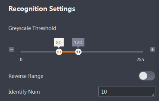 Figure 13-6 Recognition Settings
Greyscale Threshold
Here you can set the greyscale range for the detection area, so that the areas whose greyscale is within the greyscale range will be recognized.
Reverse Range
Once enabled, the greyscale value outside the configured greyscale range will be the valid range, so that the camera will recognize the areas whose greyscales are outside the configured greyscale range.
Identify Num
Here you can set the number of areas (whose greyscale is within the configured greyscale range) to be recognized.
Note
If the number of qualified areas exceeds the configured number, the camera will select the areas to output based on there sizes.
5. Set the result judgment parameters in Judge Method.
● Quantity Range: If the actual number of recognized areas is within the configured quantity range, the result will be OK, otherwise it will be NG.
6. Optional: Set extra parameters if the result is not what you have expected in Extend Parameter.
● Area Range: Defines the size of the detection area (unit: pixel).
7. Click  Test Running to test the detection according to settings.
Note
Click  Stop Running to stop the test.
13.3.2 Edge Count
The edge-counting tool can recognize and count edges based on the configured edge-counting sensitivity.
The parameter settings for the edge-counting tool include range settings, recognition settings, judge method settings, and extend parameter settings.
● In Range Settings, you can set area-related parameters.
Detection Area
Click  , and then click two different positions on the base image to draw a detection area.
Note
○ On the top left of the live view window, click  next to Base Image to view descriptions of the coordinate axes.
○ Click  beside Detection Area, and the animated tutorial will pop up in the upper-left corner of the live view panel, as is shown in the figure below.
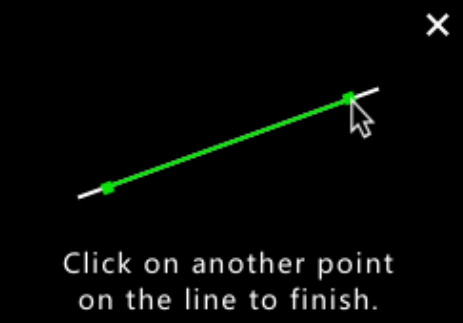
Figure 13-7 Draw Detection Area
Shielded Area
Here you can shield some areas for them not to be analyzed. Click Edit, and then click to draw polygons on the base image.
Independent Fixture
When enabled, target offset can be adjusted according to the parameter settings of the chosen fixture configuration. This function is enabled by default and automatically subscribes to the fixture configuration of the base image.
Note
Make sure you have enabled Fixture when configuring the base image. Refer to Configure Base Image for details.
● In Recognition Settings, you can set recognition-related parameters.
Sensitivity
Here you can set the sensitivity of edge counting.
Identify Num
Here you can set the maximum number of qualified edges to be recognized based on the configured sensitivity.
● In Judge Method, you can set parameters related to result judgment.
Quantity Range
If the actual number of recognized edges is within the configured quantity range, the result will be OK, otherwise it will be NG.
● In Extend Parameter
● , you can set extra parameters if the result is not what you have expected.
Edge Polarity
It represents the excessive change of color, defines the direction to look for the edges in a detection area. Here the edge is the line between two areas with different greyscales.
Black to White
The tool recognizes edges from the area with higher greyscale to the area with lower greyscale.
White to Black
The tool recognizes edges from the area with lower greyscale to the area with higher
greyscale.
All
The tool recognizes edges from the area with higher greyscale to the area with lower greyscale and from the area with lower greyscale to the area with higher greyscale.
After setting the above parameters, you can go to Output → Tool Results to set which data to transmit to the communication tool by the edge-counting tool.
The data can be transmitted are as follows: module status, detection area center X, detection area center Y, detection area width, detection area height, detection area angle, edge point X, edge point Y, line start point X, line start point Y, line end point X, line end point Y, and line angle.
13.3.3 Pattern Count
The pattern-counting tool can recognize and count patterns via the template-matching method.
The parameter settings for the pattern-counting tool include range settings, recognition settings, judge method settings, and extend parameter settings.
Range Settings
You can set area-related parameters.
Detection Area
Here you can set the area that the tool analyzes. It it set to analyze the base image by default. Click  to draw boxes on the base image, the position and size of the boxes can be adjusted manually. Click
  to set the whole base image as the detection area.
Shielded Area
Here you can shield some areas for them not to be analyzed. Click Edit, and then click  to draw polygons on the base image.
Independent Fixture
When enabled, target offset can be adjusted according to the parameter settings of the chosen fixture configuration. This function is enabled by default and automatically subscribes to the fixture configuration of the base image.
Note
Make sure you have enabled Fixture when configuring the base image. Refer to Configure Base Image for details.
Search Settings
.You can set search-related parameters
Template Area
Click Edit, and then click or  to draw boxes or polygons on the base image, the position and size of the graphics can be adjusted manually.
Note
After drawing an area, you can click  → Select similar patterns to manually set the match point. Click Reset to restore to default if needed.
Template Shielded Area
Click Edit, and then click or to draw boxes or polygons on the base image, the
position and size of the graphics can be adjusted manually.
Template Sensitivity
It can be set to "Manual" or "Auto".
● Manual: To manually adjust the template's sensitivity by setting Coarse Granularity and Greyscale Threshold.
● Auto: To automatically adjust the template's sensitivity according to the configuredsensitivity range. The higher the sensitivity, the more features of an template areawill be recognized, so the detection result will be better.
Identify Num
Here you can set the maximum number of qualified patterns to be recognized based on the configured sensitivity.
Judge Method
You can set parameters related to result judgment.
Quantity Range
If the actual number of recognized patterns is within the configured quantity range, the result will be OK, otherwise it will be NG.
Extend Parameter
You can set extra parameters if the result is not what you have expected.
Min Score
The degree of the similarity between the template and the target object, i.e., the similarity threshold. Only if the actual similarity is higher than the configured similarity threshold can the object be recognized. The similarity range is between 0 and 1, and 1 indicates completely match.
Polarity
Polarity represents the excessive change of color from the object to the background, it can be considered or ignored during recognition. If the polarity of an object's edges is different from that of the template, to ensure that the object is recognized, you need to set the polarity to Ignored, otherwise you can set it to Considered to accelerate the search.
Angle Range
If the object's angle changes but is still within the configured angle range, it can still be recognized, otherwise it cannot be recognized.
Overlap Rate
The maximum overlap rate allowed when detecting multiple objects of which two objects overlap with each other. The higher the overlap rate, the larger the area of two objects is allowed to be overlapped.
After setting the above parameters, you can go to Output → Tool Results to set which data to transmit to the communication tool by the pattern-counting tool. The data can be transmitted are as follows: module status, the number of matches, match box X, match box Y, match box width, match box height, match box angle, and score.
13.3.4 Contour Count
You can use this tool to determine the presence of contours through contour matching and to count the number of contours.
Before You Start
Make sure that you have configured the camera parameters and the base image, and added the Contour Existence tool.
Steps
1. Set the Detection Area as needed. It is set to analyze the whole base image by default. Click  or to
or to  draw on the base image, the position and size of the area can be adjusted manually.
Note
● By default, the whole base image is set to the detection area.
● Refer to How to draw an ROI? for ROI drawing details.
2. Optional: If you need to shield areas in the detection area, click  Edit on the right of Shield Area, and then click to draw polygons on the base image.
3. Optional: Enable or disable Independent Fixture as needed. When enabled, target offset can be adjusted according to the parameter settings of the chosen fixture configuration.
Note
● This function is enabled by default and automatically subscribes to the fixture configuration of the base image.
● Make sure you have enabled Fixture when configuring the base image. Refer to Configure Base Image for details.
4. Select the scale mode, threshold mode, and chain mode.
Note
By default, Auto is selected as the scale mode. For the manual mode, configure the following parameters.
Velocity Scale
The higher this value, the higher the characteristic scale, and the less the picked points from the contour. But the feature matching will be faster.
Characteristic Scale
The fineness of picking points from the contour.
Note
You can set only integers that are not larger than the velocity scale to the characteristic scale value.When the value is set to 1,it is the finest scale. Generally, adjusting this value will result in a significant change in the number of contour points. The lower the value, the finer the point-picking.
Threshold Mode
Used for setting the greyscale threshold of contour edges. The area with greyscales within the threshold will be detected.
Note
The higher this value, the less qualified number of contour edges, and the points on edges may be filtered out.
Chain Mode
It is used to set the minimum chain length for the detection area.Only when the chain length exceeds the minimum chain length, the contour will be retained.
5. Set the Identify Num.
Note
If the number of qualified contours exceeds the value you set, you can get the best contours no more than the value.
6. Set the quantity range.
Note
● If the number of identified contours is within the quantity range, the detecting result will be OK, or the result will be NG.
● The maximum quantity range is subject to the Identify Num.
7. Optional: Set extra parameters in Extend Parameter if the result is not what you have expected.
Minimum Score
The threshold of similarity between the feature template and the detected target. A higher score indicates a greater similarity. When the similarity score reaches or exceeds the threshold, the target can be found.
Match Polarity
The color change from detected target to its background. When the target's polarity is different from that of the feature template, select Ignored to make sure the target can be found. Otherwise, select Considered to shorten the finding time.
Angle Range
If the detected target has angle variations (such as rotation), you can set the relative angle range. The angle can be adjusted as needed. The default range is -180° to 180°.
Overlap Rate
The maximum allowed overlap proportion of two overlapped targets when detecting multiple targets. The higher the value, the higher the allowed overlap rate.
Algorithm Timeout
The maximum duration for running the algorithm.
● If the actual algorithm processing time exceeds this value, the algorithm will stop detecting and output NG.
● If youset this parameter to 0, there will be no limitation for the algorithm's working duration.
8. Click  Test Running to test the detection according to settings.
Note
Click  Stop Running to stop the test
13.3.5 Color Count
This tool is used for identifying colors and counting qualified colors.
Before You Start
● Make sure the greyscale image mode of the color camera is disabled.
● Make sure that you have configured the camera parameters and the base image, and added the Color Count tool.
Steps
1. Set the Detection Area as needed. It is set to analyze the whole base image by default.
Click  or
or  to draw on the base image, the position and size of the area can be adjusted manually.
Note
● By default, the whole base image is set as the detection area.
● Refer to How to draw an ROI? for ROI drawing details.
2. Optional: If you need to shield areas in the detection area, click Edit on the right of Shield Area, and then click  to draw polygons on the base image.
3. Optional: Enable or disable Independent Fixture as needed. When enabled, target offset can be adjusted according to the parameter settings of the chosen fixture configuration.
Note
● This function is enabled by default and automatically subscribes to the fixture configuration of the base image.
● Make sure you have enabled Fixture when configuring the base image. Refer to Configure Base Image for details.
4. Add colors to count and configure related parameters.
1) Click  in the Color List to add a color to count.
Note
● No more than 8 colors are allowed.
● During the color counting process, make sure you have check all the colors in the list for recognition.
2) Select a color in the list, and enter a name of the color in Color Name.
3) Pick the color to count by Color Eyedropper or by changing the Color Value Range.
Color Eyedropper
●  : To add colors from the base image, click this icon and pick colors from the base image. The pixels in the same color range will be selected and marked as green.
●  : To avoid recognizing some colors on the base image, click this icon and pick colors on the base image.
●  : To replace a color by a color from the image, click this icon and pick a color from the base image.
Color Value Range
Set the color value range, saturation range, and brightness range.
Note
You can configure these parameters to fine-tune the selected colors using the color eyedropper tool.
4) Optional: To select the complement of the currently set color range as the picking area, enable Color Inversion.
5) Optional: To configure both the hole filling area and the color patch area, enableUsing Global Area Parameters.
Note
If you disable this parameter, you should configure the hole filling area and the color
patch area for each color.
Hole Filling Area
Used for editing the threshold of hole area. A hole with an area smaller than the
threshold cannot be recognized.
Note
Holes refer to the eight-connected domains of non-target pixels that are completely
surrounded by target pixels.
Color Patch Area
The color patch with area lower than the threshold you set cannot be recognized.
5. Optional: Via the Number of Detected Blobs, configure the number of detected color patches.
6. Select the Judge Basis.
AmountJudge
If the number of detected targets is in the range you set, the result will be OK, or it will be NG.
CategoryJudges
If the detected category is the same with the category you set, the result will be OK, or it will be NG.
7. Optional: Set extra parameters in Extend Parameter if the result is not what you have expected.
● Global Hole Filling Area: the detecting threshold of all colors' hole area.
● Global Color Patch Area: the detecting threshold of all color patches' area.
8. Click  Test Running to test the detection according to settings.
Note
Click  Stop Running to stop the test
13.4 Recognition Tool
The recognition tools include the Color Contrast tool, OCR tool, Color Recognition tool, Classification Registration tool, Code Recognition tool, and Object Detection Recognition tool.
13.4.1 Color Contrast
In the detection ROI range, identify color information according to color template.
Note
This function is available only when the Greyscale Image Output function of color device is disabled. Only color camera supports this tool. If you enable the Greyscale Image Output function for a color camera, the color contrast tool can still be configured but the output result will be NG.
You can configure range settings, recognition settings, judge method, and extend parameter for the tool.
● Range Settings: You can set area-related parameters.
Detection Area
The area analyzed by the tool on the image. By default, the tool analyzes the whole image. Click  or
or  to draw the detection area on the base image on the right, you can change its position and size manually. Click
  to set the whole base image as the detection area.
Shielded Area
The shielded area will not be analyzed by the tool. Click Edit → and draw the shielded area on the base image in the live view image.
Independent Fixture
When enabled, target offset can be adjusted according to the parameter settings of the chosen fixture configuration. This function is enabled by default and automatically subscribes to the fixture configuration of the base image.
Note
Make sure you have enabled Fixture when configuring the base image. Refer to Configure Base Image for details.
● In Model Settings, you can set model-related parameters.
Model Area
The area that will be set as a template on the base image.
Shielded Area
The shielded area will not be analyzed as a template area by the tool. You can draw the shielded area on the base image.
● In Recognition Settings, you can set sensitivity-related parameters.
Sensitivity Adjustment
Adjust the sensitivity when recognizing the color.
● In Judge Method, you can set parameters related to result judgment.
Similarity Range
When the similarity between the detected diameter and that of the base image is within the range, the result will be OK, or the result will be NG.
● In Extend Parameter, you can set extra parameters if the result is not what you have expected.
Feature Type
The sensitivity of different feature type varies. Histogram Feature is more sensible to the image change.
Brightness Enable
If you enable this, the brightness change will be a reference of color contrast. By default, it is disabled.
Color Feature
This parameter gives you the hue, saturation, and brightness of the Histogram Feature.
After setting the above parameters, you can go to Output → Tool Results to set which data to transmit to the communication tool by the tool.
The data that can be transmitted are as follows: module status, best score, detection area center X, detection area center Y, detection area width, detection area height, detection area angle, and result similarity.
13.4.2 OCR
The OCR tool can recognize the text in the detection area.
Before You Start
The camera parameters and base image are configured. The OCR tool should be added.
Steps
Note
The parameters are subject to the camera model.
1. Optional: Enable Position Box Enable.
2. Optional: Click Import to import the position model list.
Note
The list name only allows upper and lower case letters, digits, and underline.
3. Draw a detection area.
Note
● See details in About ROI.
● For SC2000 and SC3000 series cameras, no more than 8 detection areas are allowed.
4. Optional: Enable or disable Independent Fixture as needed. When enabled, target offset can be adjusted according to the parameter settings of the chosen fixture configuration.
This function is enabled by default and automatically subscribes to the fixture configuration of the base image. Make sure you have enabled Fixture when configuring the base image. Refer to Configure Base Image for details.
5. Select the character filtering types.
1) Click Charter Filter.
2) Enable the function.
3) Set the number of recognize.
4) Select character types such digits and special characters.
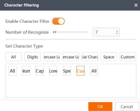
Figure 13-8 Character Filter
Note
The supported character types are subject to the camera model.
6. Set the Judge Method. The parameters of different method vary.
Quantity Range
When you set Judge Basis to Character Quantity, you need to set the range of number of characters. If the number of the actual detected characters is within the range, the process result is OK. Otherwise, the result is NG.
Min. Score
If you select Character Score as the judge basis, you need to set this. When the character score is higher than the min. score, the tool will output OK, or the tool will output NG.
Note
For SC2000 and SC3000 series cameras, this parameter may be called Similarity Range.
Character Content
When you set Judge Basis to Reference Character, you need to set the content of the string. If the specified content is recognized, the process result is OK. Otherwise, the result is NG.
7. Set more parameters.
● Select a model type according to the camera model.
Note
The default model named Common.bin is suitable for common cameras.
● Click Import and select a .bin file to import it to the camera.
Note
The list name only allows upper and lower case letters, digits, and underline.
8. For SC5000 and SC7000 Pro series cameras, you can set the following parameters.
● X Coordinate Ascending: Sort the displayed results according to the X-coordinate value in ascending order.
● Y Coordinate Ascending: Sort the displayed results according to the Y-coordinate value in descending order.
● Confidence Descending: Sort the displayed results according to the target score in descending order.
Angle Enable Defines the relative angle range tolerance for target objects. To search an object with rotation change, you need to set it Width Enable accordingly, and angle range is from -180° to 180°. Width Enable Height Enable If it is enabled, target objects whose width is within the configured range can be detected. Outside Filter Enable If it is enabled, the outside filter score can be set. When a part of the target is not in the detection area, and the proportion of the part within the edge of the search target in the whole is less than the filter score, the target cannot be searched.
Text Box Size The size of the text box
9. Click Test Running to test the tool.
Note
Click Stop Running to stop the test
13.4.3 Color Recognition
The Color Recognition tool recognizes the object color based on the trained color
templates. When the colors of different objects are obviously different, the tool can
implement the accurate classification of objects and output the result.
Before You Start
Make sure that you have configured the camera parameters and the base image, and added the Color Recognition tool.
Steps
1. Set the Detection Area according to your actual needs. It it set to analyze the whole base image by default.
Click  or
or  to draw a rectangle or circle detection area on the base image, or click
  to set the whole base image as the detection area.
2. Optional: If you need to shield areas in the detection area, click Edit on the right of
Shielded Area and draw areas.
Note
Refer to How to draw an ROI? for ROI drawing details.