
5. Interface Introduction
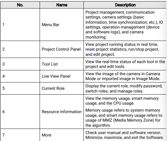
After login, the Software will load the last running project by default. If there is no project in the camera, the Software will create a blank project and run it. See the introduction of the main interface below.
Figure 5-1 Main Interface
See the description of each area in the table below.
Note
You can run multiple instances of the Software at the same time, but each instance can log into one camera only
Camera Management
Log in to the camera, and switch the camera. See details in Log Into Camera.
Project
Add, delete, import, export, and switch projects in the camera. See details in Project Management.
Communication
Add, set, or delete different communication tools for the camera. See details in Communication Settings.
Camera Settings
View camera basic information, synchronize time, etc. See details in Camera Settings.
IO Settings
Allocate IO signals, and configure project switch and project output. See details in IO Settings.
Operation Management
Search and export camera or software logs. Search, export, or delete images stored in the camera or imported to the camera. See details in Operation Management.
Camera Monitoring
Start live view of one or multiple connected cameras in a window. And manage cameras, including displaying camera list, logging in to the camera, switching the live view window division and so on. See details in Camera Monitoring.
5.2 Project Control Panel
Project control panel shows the running result of the current project. You can control the
project here
When in Camera Mode:
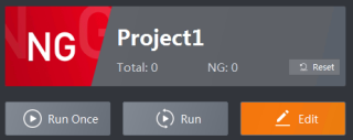
Figure 5-2 Project Control Panel in Camera Mode
When in Image Mode:
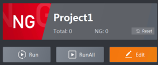
Figure 5-3 Project Control Panel in Image Mode
Description:
OK/NG (upper-left)
Real-time running result of the current project.
Total
Total running times of the current project.
NG
Total NG times of the current project.
Reset
Reset the count to zero.
Run Once (Camera Mode)
Run the project one time.
Run/Stop
Run the project continuously or stop running.
RunAll (Image Mode)
Run the project for all imported images.
Edit
Enter the project configuration page to edit the project. Refer to Create a Project for details.
5.3 Tool List
Tool list shows the tools of the current project and their running status. You can quick edit
each tool here.
Click  in the upper-right corner to switch the view between list view and statistic view.
List View:
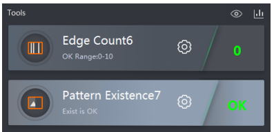
Figure 5-4 tools view mode
Left: tool name and OK condition; Right: tool settings and running result Statistic View:
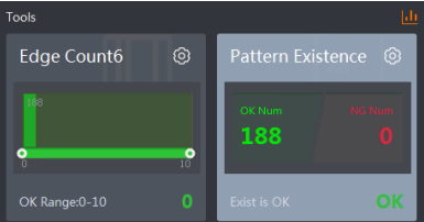
Figure 5-5 Interface Introduction statistic view mode
Upper-left: tool name; Lower-left: OK condition; Upper-right: tool settings; Lower-right: running result; Center: statistics data
Different types of tools have different statistic graph:
● If the result is judged by the count or similarity, the x-axis is the judging range and the green area is OK. You can drag to adjust the OK range.
● If the result is judged by existing or not, the statistic graph will show the count of OK and NG.
Click  to edit the tool.
Click  to show the Result Display window. You can select tool(s) to always display
tool results in the live view panel.
Note
The logic of saving result display configurations varies according to different series
cameras. For some devices, the configuration will be saved, while for other devices, the
configuration will be restored to defaults once you exit the Software.
5.4 Live View Panel
You can select the mode from Camera Mode and Image Mode in the upper-left corner of the live view panel.
Camera Mode
When you select Camera Mode, the live view panel will show the real-time image of the camera after you run the project. Select a tool in the tool list to show the real-time running result on the live view panel. See the picture below.
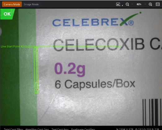
Figure 5-6 Camera Mode
You can adjust the image in the upper-right corner.
●  /
/ : Zoom in/out on the image.
●  /
/  : Original ratio / adaptive ratio
●  : Click → Path Setting to set a local path for saving image. After setting, click
  to save the current image in the local path you set. Click Saving Status to view the process of saving images.
Basic information is displayed at the bottom.
Total Cost Time
Total cost time for running the project once.
Algorithm Cost Time
Algorithm cost time for running the tool you select in the tool list once.
Tool Cost Time
Total cost time for running the tool you select in the tool list once.
BaseImage Cost Time
Base image cost time for running the project once.
X/Y
The coordinates of the cursor's position on the image.
R/G/B
The RGB value of the image at the cursor's position.
Image Mode
When you select Image Mode, the live view panel will show the imported images after you run the project. Select a tool in the tool list to show the real-time running result on the live view panel. See the picture below.
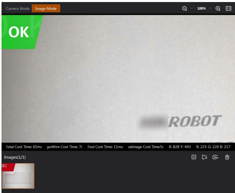
Figure 5-7 Image Mode
The supported image formats are PNG, JPG, and BMP. Icon description:
●  : Import a single image from PC.
●  : Import all images in a folder from PC.
●  : Import images from the camera. Refer to Acquired Image Management for details.
●  : Clear all imported images.
Note
● The SC2000E series and SC2000E (mini) series devices cannot store images in the camera, and thus they do not support importing images from the camera.
● For the image search during importing acquired image(s), see Acquired Image Management for details.
● For the management of imported images, see Imported Image Management for details
5.5 Add a Role
Different roles have different permissions for various operations. The roles include administrator, operator, technician, and maintainer. The administrator has the biggest range of permissions, and can create other roles and set permissions for them.
Administrator
The administrator can change the password of all roles, switch roles, and configure roles.
Click Administrator on the upper right of the Client first to conduct the following operations:
Change Password
Click Change Password, enter the old password and the new password, then confirm the new password. Click Save to finish changing the password.
Switch Roles
Click Switch Roles to switch to operator, technician, or maintainer. Enter the corresponding password to finish switching roles.
Role Management
The administrator can create the roles of operator, technician, and maintainer, and set corresponding passwords for them. The technician can be given the permissions of editing the project, global settings, or both.
Technician
The operating permissions of technician is set by the administrator.
The permissions of a technician include:
● Edit camera settings if the permmission is given.
● Edit communication settings if the permmission is given.
● Create, copy, import, export, and delete a project if given the permission of creating a project, which means the permission of configuring camera parameters, base image, tools application, and output settings are also given.
● Edit a project if given any of these permissions: configuring camera parameters, base image, tools application, and output settings. If given all these permissions, th permission of creating a project will also be given automatically.
● Edit a tool via in the tool list on the main page if given the permission of tool application.
Click Technician on the upper right of the Client to switch to other roles.
Operator
The operator can only view the monitoring page and cannot configure the settings.
Click Operator on the upper right of the Client to switch to other roles.
Maintainer
The maintainer can edit a tool via in the tool list on the main page
Note
● The maintainer cannot edit communication settings and camera settings.
● The maintainer cannot edit project on camera running page.
● The maintainer cannot edit, create, copy, import, export, or delete a project on project
management page
Click Maintainer on the upper right of the Client to switch to other roles.
5.6 More
Click  to configure language and system settings, and view the user manual and software information.
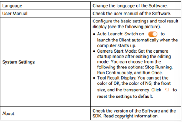
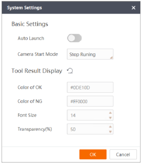 Figure 5-8 System Settings