
8. Communication Settings
ClickzClick Communication on the menu bar to check and set up the communication tools of the
current project.
Supported communication protocols: Modbus, Ethernet/IP, Profinet, FTP, UDP Server, TCP Client, TCP Server, Serial Port, Melsec, and Keyence KV.
Note
You can set the communication settings for the current project. If you want to change the communication settings for another project, load the project first.
8.1 Select Communication Mode
You can set the communication methods of the current project in Communication Settings.
Steps
Note
You can set the communication settings for the current project. If you want to change the communication settings for another project, load the project first.
1. Click Communication on the menu bar.
2. Click  to add a new communication method.
Note
You can add multiple communication methods in a project.
3. Select a method in the list to set the parameters. See details in Configure
Communication Parameters.
4. Switch on  to enable the communication method.
5. Set related parameters.
Note
● Parameters vary for different communication methods.
● Before configuring FTP parameters, configure the FTP server.
6. Optional: Select a method and click to delete the method.
8.2 Configure Communication Parameters
The camera supports the communication tools of Modbus, Ethernet/IP, Profinet, FTP, UDP Server, TCP Client, TCP Server, Serial Port, Melsec, and Keyence KV. Parameters vary among different tools.
8.2.1 Modbus
Modbus is an application layer protocol that provides communication between clients and servers connected to different types of buses or network devices. Modbus is a request and response protocol, and its services are specified by function codes.
Modbus is a passive station in the camera, and the system port number is 502
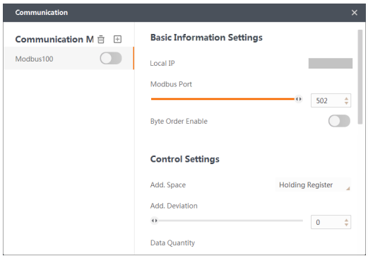
Figure 8-1 Modbus Communication Settings
8.2.2 Ethernet/IP
Ethernet/IP is an application layer protocol. You can add and use Ethernet/IP communication without further configuration after completing the settings in PLC.
8.2.3 Profinet
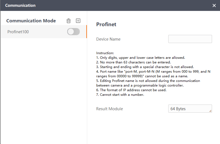
Profinet is an open industrial Ethernet standard for automation. It uses TCP/IP and IT standards. It is a real-time Ethernet that not only supports standard TCP/IP, but also provides time certainty that cannot be achieved by standard Ethernet. It is necessary to assign a camera name that is unique and consistent with the configured device name according to the naming rules, as shown in the picture below.
8.2.4 FTP
FTP communication can store the qualified images on FTP in the format of JPG.
FTP Service Configuration
Before setting FTP parameters, configure the parameters for FTP service and enable FTP Service.
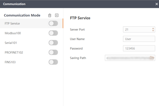
Figure 8-3 FTP Service Configuration
Sever Port
Configure the port number of FTP service, which should be the same as that communicates with FTP.
User Name
Configure the user name to log in to the FTP service.
Password
Configure the password to log in to the FTP service.
Saving Path
Set the saving path for the data of FTP service in the local PC.
Set FTP Parameters
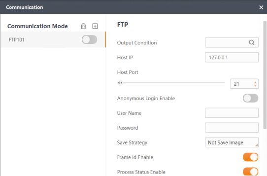
Figure 8-4 FTP Parameters
Output Condition
Condition for saving images on FTP. Click to subscribe information on modules such as camera image, base image, tools, and communication.
Host IP
IP address of the FTP server. 127.0.0.1 represents that the current PC is used as the FTP server.
Host Port
Port number of the FTP server.
Anonymous Login Enable
Switch on if the FTP server does not require a user name and password to log in.
Note
When anonymous login is enabled, the user name is shown as anonymous and the
password is empty. Entering user name or password is invalid.
User Name & Password
If anonymous login is disabled, specify the user name and password to log into the FTP server.
Save Strategy
Set the condition for saving images.
Frame ID Enable
Switch on to include frame ID in the image name.
Process Status Enable
Switch on to include running status in the image name.
Start End Text
Set the start and end text of the image name.
Separator Text
Set the separator text between different items in the image name.
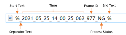
Figure 8-5 Separator Text
Directory Type
Not Create
All the images will be stored in the default file folder in the server.
Create
New file folders will be created for storing each day's images.
Max file Num
the maximum number of images allowed for a single file folder.
Dir Increment Enable
if you do not enable this, new images will not be stored when the number of stored images reaches the upper limit of allowed images. If you do not enable this, a new file folder will be created for storing new images when the number of stored images reaches the upper limit of allowed images.
FTP Link Check
Click Execute to test the connection with the FTP server with the settings above.
8.2.5 UDP Server
The camera can communicate with the UDP tool. You need to specify the parameters according to the setting of the UDP tool.
Local IP
IP address of the camera. The IP address of the client of the UDP tool should be same with the address.
Local Port
The port number of the client of the UDP tool.
Target IP
The IP address of the server of the UDP tool.
Target Port
The port number of the server of the UDP tool.
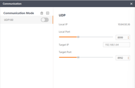
Figure 8-6 UDP
8.2.6 TCP Client
The camera can be used as the TCP client and communicate with a specific TCP server. Specify the IP and port number of the TCP server.
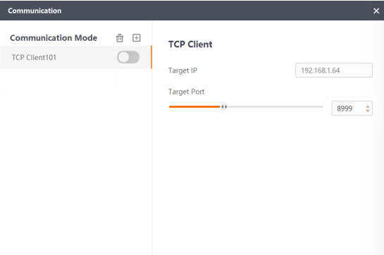 Figure 8-7 Configure TCP Client
8.2.7 TCP Server
The camera can be used as the TCP server and communicate with a specific TCP client. Set the local port number and then enter the IP address and port number on the TCP client.
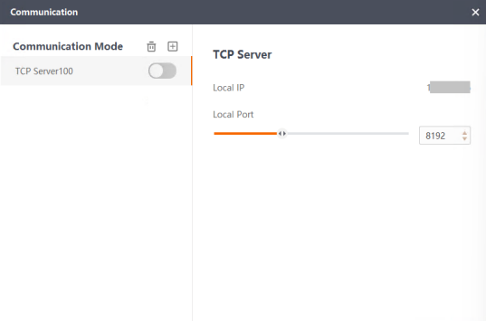
Figure 8-8 Configure TCP Server
8.2.8 Serial Port
The camera can communicate with another device through the RS-232 serial ports.
Note
Make sure the camera is connected to the device with RS-232 serial port via a 17-pin cable. Refer to the quick start guide of the camera for instructions on connecting serial ports.
You need to set the following parameters.
Serial Port Mode
Only RS-232 is supported.
Baud Rate
Specify the rate according to actual condition. Make sure the baud rate is the same between the two ends of the communication.
Data Bit
The default value is 8 and cannot be changed.
Parity Bit
Select from None, Odd, and Even.
Stop Bit
Select from 1 and 2.
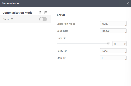
Figure 8-9 Configure Serial Port
8.2.9 MELSEC
The camera can read/write the soft elements of the PLC via the MELSEC protocol.
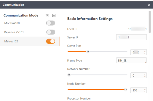
Figure 8-10 MELSEC Parameters
Parameter description:
Basic Information Settings
Server IP
IP address of the MELSEC PLC.
Server Port
Port No. of the MELSEC PLC.
Frame Type
The device can use ASCII and binary data in communication via MELSEC protocol, so its frame type includes BIN_1E, BIN_3E, BIN_4E, ASCII_1E, ASCII_3E, and ASCII_4E.
Note
● When the device accesses the PLC of MELSEC Q series, select 1E, 3E, or 4E as the frame type.
● When the device accesses the PLC of MELSEC FX3U series, select 1E as the frame type.
Network Number
The network number of the target station.
Node Number
The number of the target nodes.
Byte Order Enable
If it is enabled, the data will be stored in byte order.
Poll Interval
Polling frequency. The client will send requests to the server and the server will receive requests at the set time interval.
Timeout
The time that the device waiting for the response returned from the PLC.
Control Settings / Status Settings / Result Area Settings / Instruction Area Settings
The parameter of different modules are shown below.
Add Space
Type of the soft element. By default, it is D, which presents the data register.
Add Deviation
Offset value of the data.
Data Size
Max. number of data stored in the soft element.
8.2.10 Keyence KV
The camera can communicate with the PLC via the Keyence KV protocol.
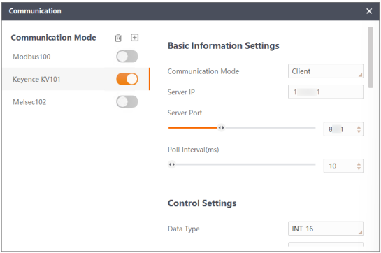
Figure 8-11 Keyence KV Parameters
Parameter description:
Basic Information Settings
Communication Mode
● Client: The camera can be used as the server to communicate with the Keyence KV client.
● Server: The camera can be used as the client to communicate with the Keyence KV server.
Client/Server IP
● For Client communication mode, enter the IP address of the Keyence KV client.
● For Server communication mode, enter the IP address of the Keyence KV server.
Poll Interval
Polling frequency. Theclient will send requests to the server and the server will receive requests at the set time interval.
Control Settings / Status Settings / Result Area Settings / Instruction Area Settings
The parameter of different modules are shown below.
Data Type
Type of the data transmited between the device and the Keyence KC client/server.
Soft Element Type
Type of the soft element. By default, it is D, which presents the data register.
Soft Element Address
The address of soft element in the corresponding modules (control, status, result, and instruction).
Soft Element Size
Max. number of data stored in the soft element.