
6. Parameter Description
Group P0 Basic Function

1: G model: Applicable to constant torque load.
2: P model: Applicable to constant power load.
KE300 series inverter adopts G/P combination mode, the suitable motor power of constant torque load (G model) is one size smaller than fan and pump loads (P model).

0: V/F control
It is suitable for general purpose application such as pumps, fans etc. One inverter can drive multiple motors.
1: Sensorless vector control
It is widely used for the application which requires high torque at low speed, high speed accuracy, and quicker dynamic response, such as machine tool, injection molding machine, centrifugal machine and wire-drawing machine, etc.
Note:
The autotuning of motor parameters must be accomplished properly if you use the sensorless vector control. How to autotuning of motor parameters please refer to P4 Group.
In order to achieve better control characteristic, the parameters of vector control (P2 Group) should be adjusted.
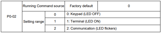
Select the input channel for control command. The inverter control commands include start, stop, forward run, reverse run, Jog and so on.
0: Keypad (“LOCAL/REMOT” LED OFF)
Both RUN and STOP/RST keys are used for running command control. If multifunction key QUICK/JOG is set as FWD/REV switching function (P7-01 is set to be 2), it will be used to change the rotating orientation. If multifunction key QUICK/JOG is set as FWD jog (P7-01 is set to be 3) or REV jog (P7-01 is set to be 4), it will be used for jog running.
1: Terminal (“LOCAL/REMOT” LED ON)
The operations, including FWD, REV, JOGF, JOGR, etc. can be controlled by multifunctional input
terminals.
2: Communication (“LOCAL/REMOT” LED flickers)
The operation of inverter can be controlled by host through communication.
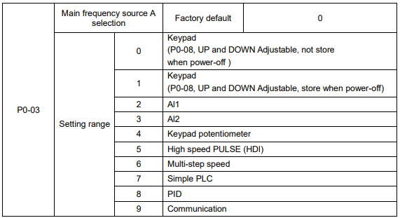
0: Keypad (not store)
The initial value is the value of P0-08. The setting frequency value of inverter can be modified through the keys “▲” and “▼” of the keyboard (or UP and DOWN of multifunctional input terminals).
“Not store” means that the setting frequency is recovered to the value of P0-08 in case of inverter poweroff.
1: Keypad (store)
The initial value is the value of P0-08.
“Store” means that the setting frequency remains the same as the value before inverter power-off.
2: Al1
3: Al2
The reference frequency is set by analog input. KE300 series inverter provides 2 analog input terminals (AI1, AI2). Both of AI1 and AI2 are 0~10V / 0~20mA input terminal.
User can select the corresponding relation between the objective frequency and the input voltage value of AI freely. KE300 series inverter provides 3 corresponding relation curves which can be set by users through P4 group function code.
4: Keypad potentiometer
The reference frequency is set by keypad potentiometer.
5: High speed PULSE (HDI)
The reference frequency is set by high speed pulse.
Pulse reference signal specification: the voltage range is 9V to 30V, and the frequency range is 0kHz to 50kHz. Pulse given can only be input from the multifunctional input terminal HDI.
6: Multi-step speed
The reference frequency is determined by P4 and PC groups. The selection of steps is determined by combination of multi-step speed terminals.
7: Simple PLC
User can set reference frequency, hold time, running direction of each step and acceleration/deceleration time between steps. For details, please refer to description of PC group.
8: PID
The reference frequency is the result of PID adjustment. For details, please refer to description of PA group.
9: Communication
The reference frequency is set through RS485. For details, please refer to Modbus protocol in Chapter 9.

When the auxiliary frequency source is used as independent frequency reference channel (i.e. frequency source switching from A to B), it is used in the same way as the main frequency source. Please refer to P0-03.
When the auxiliary frequency source is used as combination reference, please note:
1. If the auxiliary frequency source is keypad reference, the frequency (P0-08) is invalid, and it needs to adjust the main reference frequency through the keys “▲”and “▼” of the keyboard (or UP and DOWN of multifunctional input terminals).
2. If the auxiliary frequency source is analog input reference (AI1, AI2) or pulse input reference, 100% of input corresponds to the auxiliary frequency source range (refer to P0-05 and P-06).
3. If the frequency source is pulse input reference, it is similar to the analog input reference.
Note: P0-03 and P0-04 can’t be set to be the same value. Otherwise, disorder will occur.


When the frequency source selection is frequency combination reference (P0-07 is set to 1 or 3), the two parameters are used to determine the adjustment range of auxiliary frequency source.
P0-05 is used to determine the relative object of that range. If it is relative to maximum frequency A, that range will change with the main frequency A.
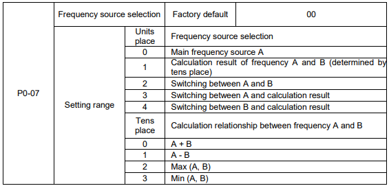
Units place: Frequency source selection
0: Main frequency source A
Reference frequency = A
1: Calculation result of frequency A and B
Reference frequency = Calculation result of frequency A and B (determined by tens place)
2: Switching between A and B
If the multifunctional input terminal HDI (P4-0X=18:frequency switching) is invalid, reference frequency = A.
If the multifunctional input terminal HDI (frequency source switching) is valid, reference frequency = B.
3: Switching between A and calculation result
If the multifunctional input terminal HDI (frequency switching) is invalid, reference frequency = A.
If the multifunctional input terminal HDI (frequency switching) is valid, reference frequency = calculation result.
4: Switching between B and calculation result
If the multifunctional input terminal HDI (frequency switching) is invalid, reference frequency = B.
If the multifunctional input terminal HDI (frequency switching) is valid, reference frequency = calculation result.
Tens place: Frequency source main/auxiliary calculation relationship
0: A + B
Reference frequency = A + B, achieving frequency combination given function.
1: A - B
Reference frequency = A - B
2: Max (A, B)
Reference frequency = Max (A, B)
3: Min (A, B)
Reference frequency = Min (A, B)
Note: When the frequency source selection is main/auxiliary calculation, the preset offset frequency can be set via P0-21, which can be added to main/auxiliary calculation result to meet different kinds of demand.

When the main frequency source is selected as “Keypad” or “Terminals UP/DN”, this function code is the initial value of frequency digital setting of the inverter.

Through modifying this function code, it can change the rotary direction of the motor without changing motor wiring. It’s equal to adjust any two lines of the motor (U, V and W) and further change the rotary direction of the motor.
Note: If the parameters are restored, the running direction will be back to its original status.

The maximum output frequency of KE300 series inverter is 3000Hz.
When P0-22 is set to 1, frequency resolution is 0.1Hz, P0-10 setting range is 50.0Hz~3000.0Hz;
When P0-22 is set to 2, frequency resolution is 0.01Hz, P0-10 setting range is 50.0Hz~300.0Hz.
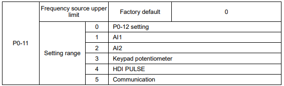
It is used to define the source of frequency upper limit. The frequency upper limit can be sourced from either digital setting (P0-12) or analog input. When the analog input is used to set the frequency upper limit, 100% of analog input setting is relative to P0-12.
Notice:
Upper frequency limit should exceed than the maximum frequency.
Output frequency should not exceed upper frequency limit.
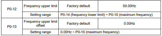
When the frequency source upper limit is analog value or HDI pulse, P0-13 is used as the setting value’s offset. The combination of this offset frequency and P0-12 is used as the final setting value of frequency upper limit.

If the reference frequency is lower than frequency lower limit, the inverter can stop, or run with lower limit frequency, or run at zero speed, which is set by P8-14.

Carrier frequency will affect the noise of motor and the EMI of inverter.
If the carrier frequency is increased, it will cause better current wave, less harmonic current and lower noise of motor.
Notice:
The factory default is optimal in most cases. Modification of this parameter is not recommended. If the carrier frequency exceeds the factory default, the inverter must be derated because the higher carrier frequency will cause more switching loss, higher temperature rise of inverter and stronger electromagnetic interference.
If the carrier frequency is lower than the factory default, it is possible to cause less output torque of motor and more harmonic current.
The effect of modifying carrier frequency is as following

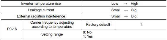
The inverter can automatically adjust the carrier frequency according to its temperature. This function can reduce the possibility of overheat alarm of the inverter.

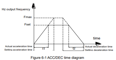
Acceleration time is the time of accelerating from 0Hz to ACC/DEC time reference frequency (P0-25).
Deceleration time is the time of decelerating from ACC/DEC time reference frequency (P0-25) to 0Hz.
Please refer to following figure.
There are totally four groups of acceleration/deceleration time which can be selected via the multifunctional digital input terminals.
Group 1: P0-17, P0-18;
Group 2: P8-03, P8-04;
Group 3: P8-05, P8-06;
Group 4: P8-07, P8-08.

KE300 series inverter offers three ACC/DEC time units, they are 1s, 0.1s, 0.01s.
Note: When modifying this function parameter, 4 group ACC/DEC time display decimal place
changes, the corresponding ACC/DEC time also changes.

This function code is only valid when frequency source is set to be main/auxiliary calculation.
When frequency source is set to be main/auxiliary calculation, P0-21 is offset frequency, which can be
combined with main/auxiliary calculation result setting as reference frequency.

This parameter is used to determine the resolution of all the function codes related to frequency.
When frequency resolution is 0.1Hz, the MAX. output frequency is 3000.0Hz. When frequency resolution is 0.01Hz, the MAX. output frequency is 300.00Hz.
Note: When modifying this parameter, the decimal place of all the parameters related to frequency changes, the corresponding frequency value changes too.

This function is only valid when frequency source is set by keypad
0: No store means that the keypad setting frequency value would recover to the value of P0-08 (preset frequency) after the inverter stopped. The frequency modification by keys “▲”, “▼” or terminal UP, DOWN would be cleared.
1: Store means that the keypad setting frequency would recover to the last frequency when inverter stopping. The frequency modification by keys “▲”, “▼” or terminal UP, DOWN is valid.

ACC/DEC time is ACC/DEC time from 0Hz to the frequency set by P0-25, figure 6-1 is ACC/DEC time
schematic diagram.
When P0-25 is set to 1, ACC/DEC time is related to setting frequency. The motor acceleration will change if setting frequency changes frequently

This parameter is only valid when frequency source is set by keypad.
It is used to confirm which mode would be used to modify setting frequency when keys “▲”, “▼” or terminal UP, DOWN acts, namely, whether reference frequency increases/decreases on the basic of running frequency, or increases/decreases on the basic of setting frequency
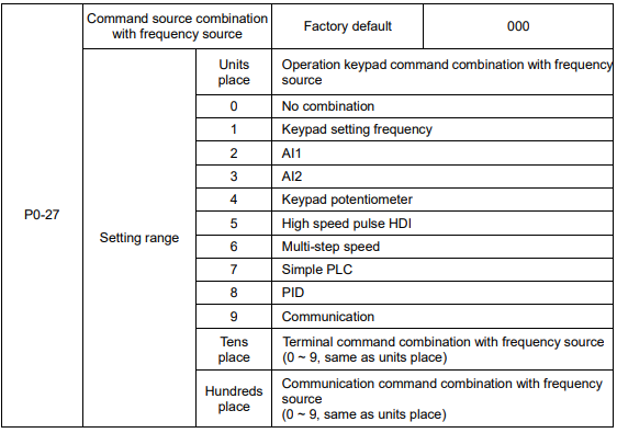
Defining the combination between three running command channels and nine frequency given channels, it’s convenient to achieve synchronous switching.
The meaning of the above frequency given channels is the same as the selection of the main frequency source A (P0-03). Please refer to P0-03.
Different running command channels can bind the same frequency given channel.
When command source binds frequency source & command source is valid, the frequency source set by P0-03 ~ P0-07 is invalid.
Group P1 Motor Parameters
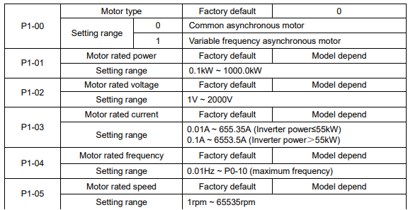
1. Please set the parameters correctly according to the motor nameplate.
2. In order to achieve superior control performance, please perform motor parameters autotuning. The accuracy of autotuning is closely related to the correct setting of the rated motor parameters.
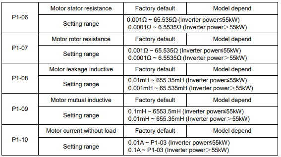
P1-06 ~ P1-10 are motor parameters, which cannot be found on the motor nameplate, and are obtained via the inverter autotuning. The static autotuning only can obtain P1-06 ~ P1-08. The rotation autotuning not only can obtain P1-06 ~ P1-10, but also can get current loop PI parameter, etc. When P1-01 or P1-02 changed, the inverter will change P1-06 ~ P1-10 automatically, and restore P1-06 ~ P1-10 as standard Y series motor parameters.
If motor parameters autotuning failed in the site, please input the related parameters provided by the motor manufacturer.

0: No operation, prohibit motor parameter autotuning.
1: Motor parameter static autotuning, suitable for the applications which the asynchronous motor is not easy to disconnect with the load, and cannot make rotation autotuning.
Before static autotuning, please set the motor type and motor parameters (P1-00 ~ P1-05) correctly. The inverter can obtain P1-06 ~ P1-08 via static autotuning.
Action description: Set the function code to be 1, the keypad displays “TUNE”, then press RUN key, the inverter will make static autotuning.
2: Motor parameter rotation autotuning
To ensure the dynamic control performance of inverter, please select rotation autotuning. During the rotation autotuning, the motor must be disconnected with the load (i.e. no-load). During rotation autotuning, the inverter will make static autotuning at first, and then accelerates to 80% motor rated frequency according to acceleration time P0-17, holding for a while, at last decelerates to stop according to deceleration time P0-18 and finish autotuning.
Before rotation autotuning, please set motor type and motor parameters P1-00 ~ P1-05, during rotation autotuning, the inverter can obtain P1-06~P1-10, vector control current loop PI parameters P2-13 ~ P2-16.
Action description: Set the function code to 2, the keypad displays “TUNE”, then press RUN key, the inverter will make rotation autotuning.
Note: Autotuning is valid only on keypad operation mode, cannot make autotuning under terminal and communication operation modes.