
6. Parameter Description
Group P0 Basic Function

1: G model: Applicable to constant torque load.
2: P model: Applicable to constant power load.
KE300 series inverter adopts G/P combination mode, the suitable motor power of constant torque load (G model) is one size smaller than fan and pump loads (P model).

0: V/F control
It is suitable for general purpose application such as pumps, fans etc. One inverter can drive multiple motors.
1: Sensorless vector control
It is widely used for the application which requires high torque at low speed, high speed accuracy, and quicker dynamic response, such as machine tool, injection molding machine, centrifugal machine and wire-drawing machine, etc.
Note:
The autotuning of motor parameters must be accomplished properly if you use the sensorless vector control. How to autotuning of motor parameters please refer to P4 Group.
In order to achieve better control characteristic, the parameters of vector control (P2 Group) should be adjusted.
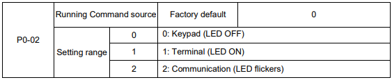
Select the input channel for control command. The inverter control commands include start, stop, forward run, reverse run, Jog and so on.
0: Keypad (“LOCAL/REMOT” LED OFF)
Both RUN and STOP/RST keys are used for running command control. If multifunction key QUICK/JOG is set as FWD/REV switching function (P7-01 is set to be 2), it will be used to change the rotating orientation. If multifunction key QUICK/JOG is set as FWD jog (P7-01 is set to be 3) or REV jog (P7-01 is set to be 4), it will be used for jog running.
1: Terminal (“LOCAL/REMOT” LED ON)
The operations, including FWD, REV, JOGF, JOGR, etc. can be controlled by multifunctional input
terminals.
2: Communication (“LOCAL/REMOT” LED flickers)
The operation of inverter can be controlled by host through communication.
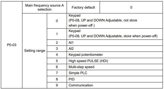
0: Keypad (not store)
The initial value is the value of P0-08. The setting frequency value of inverter can be modified through the keys “▲” and “▼” of the keyboard (or UP and DOWN of multifunctional input terminals).
“Not store” means that the setting frequency is recovered to the value of P0-08 in case of inverter poweroff.
1: Keypad (store)
The initial value is the value of P0-08.
“Store” means that the setting frequency remains the same as the value before inverter power-off.
2: Al1
3: Al2
The reference frequency is set by analog input. KE300 series inverter provides 2 analog input terminals (AI1, AI2). Both of AI1 and AI2 are 0~10V / 0~20mA input terminal.
User can select the corresponding relation between the objective frequency and the input voltage value of AI freely. KE300 series inverter provides 3 corresponding relation curves which can be set by users through P4 group function code.
4: Keypad potentiometer
The reference frequency is set by keypad potentiometer.
5: High speed PULSE (HDI)
The reference frequency is set by high speed pulse.
Pulse reference signal specification: the voltage range is 9V to 30V, and the frequency range is 0kHz to 50kHz. Pulse given can only be input from the multifunctional input terminal HDI.
6: Multi-step speed
The reference frequency is determined by P4 and PC groups. The selection of steps is determined by combination of multi-step speed terminals.
7: Simple PLC
User can set reference frequency, hold time, running direction of each step and acceleration/deceleration time between steps. For details, please refer to description of PC group.
8: PID
The reference frequency is the result of PID adjustment. For details, please refer to description of PA group.
9: Communication
The reference frequency is set through RS485. For details, please refer to Modbus protocol in Chapter 9.

When the auxiliary frequency source is used as independent frequency reference channel (i.e. frequency source switching from A to B), it is used in the same way as the main frequency source. Please refer to P0-03.
When the auxiliary frequency source is used as combination reference, please note:
1. If the auxiliary frequency source is keypad reference, the frequency (P0-08) is invalid, and it needs to adjust the main reference frequency through the keys “▲”and “▼” of the keyboard (or UP and DOWN of multifunctional input terminals).
2. If the auxiliary frequency source is analog input reference (AI1, AI2) or pulse input reference, 100% of input corresponds to the auxiliary frequency source range (refer to P0-05 and P-06).
3. If the frequency source is pulse input reference, it is similar to the analog input reference.
Note: P0-03 and P0-04 can’t be set to be the same value. Otherwise, disorder will occur.


When the frequency source selection is frequency combination reference (P0-07 is set to 1 or 3), the two parameters are used to determine the adjustment range of auxiliary frequency source.
P0-05 is used to determine the relative object of that range. If it is relative to maximum frequency A, that range will change with the main frequency A.
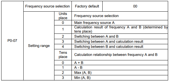
Units place: Frequency source selection
0: Main frequency source A
Reference frequency = A
1: Calculation result of frequency A and B
Reference frequency = Calculation result of frequency A and B (determined by tens place)
2: Switching between A and B
If the multifunctional input terminal HDI (P4-0X=18:frequency switching) is invalid, reference frequency = A.
If the multifunctional input terminal HDI (frequency source switching) is valid, reference frequency = B.
3: Switching between A and calculation result
If the multifunctional input terminal HDI (frequency switching) is invalid, reference frequency = A.
If the multifunctional input terminal HDI (frequency switching) is valid, reference frequency = calculation result.
4: Switching between B and calculation result
If the multifunctional input terminal HDI (frequency switching) is invalid, reference frequency = B.
If the multifunctional input terminal HDI (frequency switching) is valid, reference frequency = calculation result.
Tens place: Frequency source main/auxiliary calculation relationship
0: A + B
Reference frequency = A + B, achieving frequency combination given function.
1: A - B
Reference frequency = A - B
2: Max (A, B)
Reference frequency = Max (A, B)
3: Min (A, B)
Reference frequency = Min (A, B)
Note: When the frequency source selection is main/auxiliary calculation, the preset offset frequency can be set via P0-21, which can be added to main/auxiliary calculation result to meet different kinds of demand.

When the main frequency source is selected as “Keypad” or “Terminals UP/DN”, this function code is the initial value of frequency digital setting of the inverter.

Through modifying this function code, it can change the rotary direction of the motor without changing motor wiring. It’s equal to adjust any two lines of the motor (U, V and W) and further change the rotary direction of the motor.
Note: If the parameters are restored, the running direction will be back to its original status.

The maximum output frequency of KE300 series inverter is 3000Hz.
When P0-22 is set to 1, frequency resolution is 0.1Hz, P0-10 setting range is 50.0Hz~3000.0Hz;
When P0-22 is set to 2, frequency resolution is 0.01Hz, P0-10 setting range is 50.0Hz~300.0Hz.
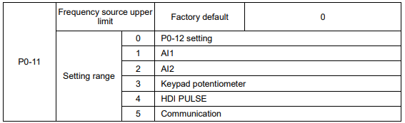
It is used to define the source of frequency upper limit. The frequency upper limit can be sourced from either digital setting (P0-12) or analog input. When the analog input is used to set the frequency upper limit, 100% of analog input setting is relative to P0-12.
Notice:
Upper frequency limit should exceed than the maximum frequency.
Output frequency should not exceed upper frequency limit.
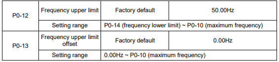
When the frequency source upper limit is analog value or HDI pulse, P0-13 is used as the setting value’s offset. The combination of this offset frequency and P0-12 is used as the final setting value of frequency upper limit.

If the reference frequency is lower than frequency lower limit, the inverter can stop, or run with lower limit frequency, or run at zero speed, which is set by P8-14.

Carrier frequency will affect the noise of motor and the EMI of inverter.
If the carrier frequency is increased, it will cause better current wave, less harmonic current and lower noise of motor.
Notice:
The factory default is optimal in most cases. Modification of this parameter is not recommended. If the carrier frequency exceeds the factory default, the inverter must be derated because the higher carrier frequency will cause more switching loss, higher temperature rise of inverter and stronger electromagnetic interference.
If the carrier frequency is lower than the factory default, it is possible to cause less output torque of motor and more harmonic current.
The effect of modifying carrier frequency is as following

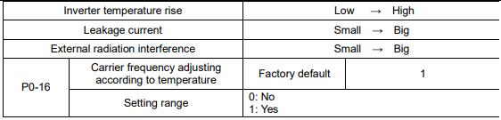
The inverter can automatically adjust the carrier frequency according to its temperature. This function can reduce the possibility of overheat alarm of the inverter.

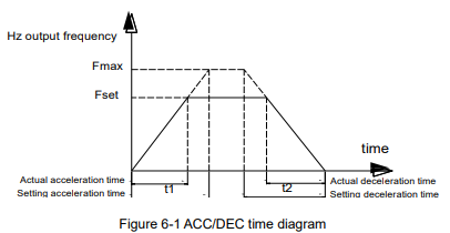
Acceleration time is the time of accelerating from 0Hz to ACC/DEC time reference frequency (P0-25).
Deceleration time is the time of decelerating from ACC/DEC time reference frequency (P0-25) to 0Hz.
Please refer to following figure.
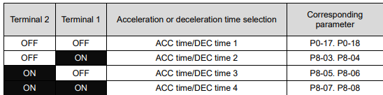
There are totally four groups of acceleration/deceleration time which can be selected via the multifunctional digital input terminals.
Group 1: P0-17, P0-18;
Group 2: P8-03, P8-04;
Group 3: P8-05, P8-06;
Group 4: P8-07, P8-08.

KE300 series inverter offers three ACC/DEC time units, they are 1s, 0.1s, 0.01s.
Note: When modifying this function parameter, 4 group ACC/DEC time display decimal place
changes, the corresponding ACC/DEC time also changes.

This function code is only valid when frequency source is set to be main/auxiliary calculation.
When frequency source is set to be main/auxiliary calculation, P0-21 is offset frequency, which can be
combined with main/auxiliary calculation result setting as reference frequency.

This parameter is used to determine the resolution of all the function codes related to frequency.
When frequency resolution is 0.1Hz, the MAX. output frequency is 3000.0Hz. When frequency resolution is 0.01Hz, the MAX. output frequency is 300.00Hz.
Note: When modifying this parameter, the decimal place of all the parameters related to frequency changes, the corresponding frequency value changes too.

This function is only valid when frequency source is set by keypad
0: No store means that the keypad setting frequency value would recover to the value of P0-08 (preset frequency) after the inverter stopped. The frequency modification by keys “▲”, “▼” or terminal UP, DOWN would be cleared.
1: Store means that the keypad setting frequency would recover to the last frequency when inverter stopping. The frequency modification by keys “▲”, “▼” or terminal UP, DOWN is valid.

ACC/DEC time is ACC/DEC time from 0Hz to the frequency set by P0-25, figure 6-1 is ACC/DEC time
schematic diagram.
When P0-25 is set to 1, ACC/DEC time is related to setting frequency. The motor acceleration will change if setting frequency changes frequently

This parameter is only valid when frequency source is set by keypad.
It is used to confirm which mode would be used to modify setting frequency when keys “▲”, “▼” or terminal UP, DOWN acts, namely, whether reference frequency increases/decreases on the basic of running frequency, or increases/decreases on the basic of setting frequency
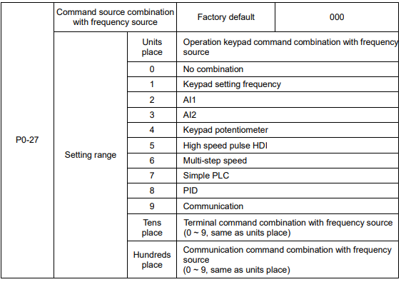
Defining the combination between three running command channels and nine frequency given channels, it’s convenient to achieve synchronous switching.
The meaning of the above frequency given channels is the same as the selection of the main frequency source A (P0-03). Please refer to P0-03.
Different running command channels can bind the same frequency given channel.
When command source binds frequency source & command source is valid, the frequency source set by P0-03 ~ P0-07 is invalid.
Group P1 Motor Parameters
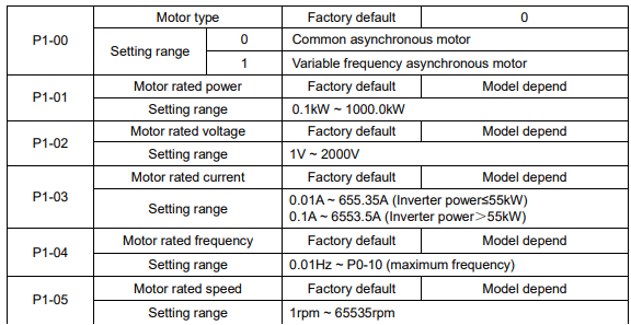
1. Please set the parameters correctly according to the motor nameplate.
2. In order to achieve superior control performance, please perform motor parameters autotuning. The accuracy of autotuning is closely related to the correct setting of the rated motor parameters.
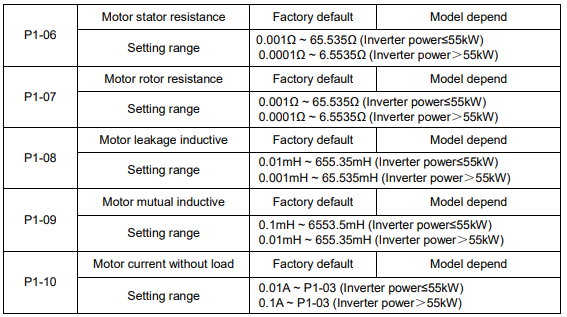
P1-06 ~ P1-10 are motor parameters, which cannot be found on the motor nameplate, and are obtained via the inverter autotuning. The static autotuning only can obtain P1-06 ~ P1-08. The rotation autotuning not only can obtain P1-06 ~ P1-10, but also can get current loop PI parameter, etc. When P1-01 or P1-02 changed, the inverter will change P1-06 ~ P1-10 automatically, and restore P1-06 ~ P1-10 as standard Y series motor parameters.
If motor parameters autotuning failed in the site, please input the related parameters provided by the motor manufacturer.

0: No operation, prohibit motor parameter autotuning.
1: Motor parameter static autotuning, suitable for the applications which the asynchronous motor is not easy to disconnect with the load, and cannot make rotation autotuning.
Before static autotuning, please set the motor type and motor parameters (P1-00 ~ P1-05) correctly. The inverter can obtain P1-06 ~ P1-08 via static autotuning.
Action description: Set the function code to be 1, the keypad displays “TUNE”, then press RUN key, the inverter will make static autotuning.
2: Motor parameter rotation autotuning
To ensure the dynamic control performance of inverter, please select rotation autotuning. During the rotation autotuning, the motor must be disconnected with the load (i.e. no-load). During rotation autotuning, the inverter will make static autotuning at first, and then accelerates to 80% motor rated frequency according to acceleration time P0-17, holding for a while, at last decelerates to stop according to deceleration time P0-18 and finish autotuning.
Before rotation autotuning, please set motor type and motor parameters P1-00 ~ P1-05, during rotation autotuning, the inverter can obtain P1-06~P1-10, vector control current loop PI parameters P2-13 ~ P2-16.
Action description: Set the function code to 2, the keypad displays “TUNE”, then press RUN key, the inverter will make rotation autotuning.
Note: Autotuning is valid only on keypad operation mode, cannot make autotuning under terminal and communication operation modes.
Group P2 Vector Control Parameters
Group P2 is valid only for vector control. That is to say, when P0-01=0 or 1, it is valid, and when P0-01=2, it is invalid
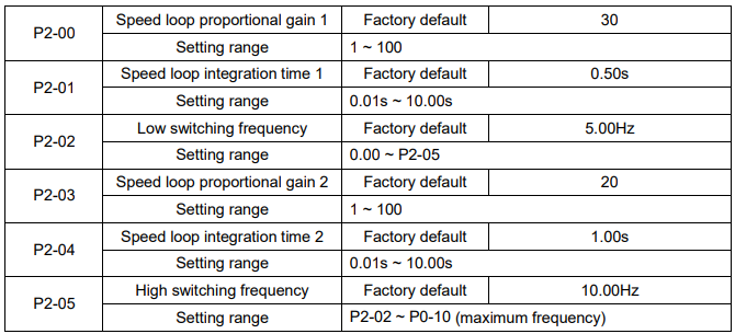
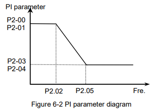
P2-00 and P2-01 are PI adjustment parameters when the running frequency is lower than low switching frequency (P2-02). P2-03 and P2-04 are PI adjustment parameters when the running frequency is higher than high switching frequency (P2-05). PI parameter of frequency channel between low switching frequency and high switching frequency is linear switching between two groups of PI parameters, as shown in the figure below:
The speed dynamic response characteristics of the vector control can be adjusted by setting the proportional coefficient and integration time of the speed regulator.
Increasing the proportional gain or reducing the integration time can accelerate the dynamic response of the speed loop. However, if the proportional gain is too large or the integration time is too short, it will cause the oscillation of the system.
Recommended adjustment method:
If factory default cannot meet the requirements, the relevant parameter values can be subject to fine tuning.
Increase the proportional gain while ensuring no oscillation to the system, and then reduce the integration time to ensure that the system has quick response characteristics and small overshoot.
Caution: Improper PI parameter setting may cause too large speed overshoot. Voltage fault may occur when the overshoot drops.

For sensorless vector control, this parameter is used to adjust the speed stabilizing precision of the motor.
When the speed is too low due to heavy load of motor, this parameter needs to be enlarged, vice versa.

Under vector control mode, the output of speed loop regulator is torque current command. This parameter is used to filter the torque command. This parameter needs no adjustment generally and this filter time can be increased in case of huge speed fluctuation. In case of oscillation of motor, this parameter should be reduced properly.
The speed loop filter time is low, and the inverter output torque may fluctuate greatly, but the response is quick.

During deceleration, over excitation control can suppress bus voltage increase, avoid over voltage fault.
The bigger over excitation gain is, the better the suppression result is.
For the application which over voltage fault happens frequently during deceleration, the over excitation gain needs to be increased. But the current would be increased if the over excitation is too bigger, so you need to set the suitable over excitation gain.
For the small inertia situation, voltage doesn’t increase during motor deceleration, please set over excitation gain to 0. For the application with braking resistor, please also set over excitation gain to 0.
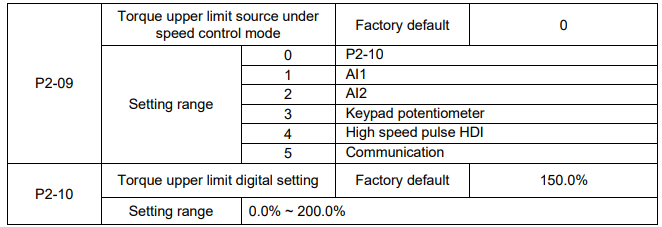
In the speed control mode, the maximum of the inverter output torque is controlled by the torque upper limit source.
P2-09 is used to select the setting source of torque upper limit. When setting via the analog value, high speed pulse HDI, communication, 100% of the relevant setting corresponds to P2-10, and 100% of P2-10 is the inverter rated torque.
Group P3 V/F Control Parameters
This group of function code is enabled only for V/F control (P0-01=2) and is invalid for vector control. V/F control is applicable for the general loads such as fan and pump or the applications where one inverter drives multiple motors or the inverter power is one level lower or higher than the motor power.
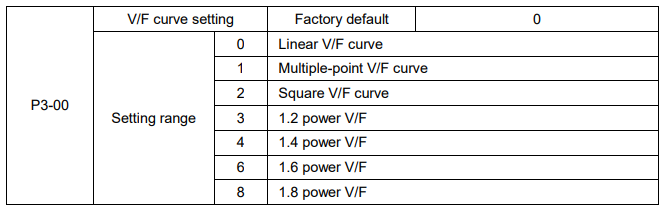
0: Linear V/F curve. It is suitable for common constant torque load.
1: Multiple-point V/F curve. It is suitable for the special loads such as dehydrator and centrifugal machine.
2: Square V/F curve. It is suitable for the centrifugal loads such as fan and pump.
3~8: VF curve between linear VF and square VF.
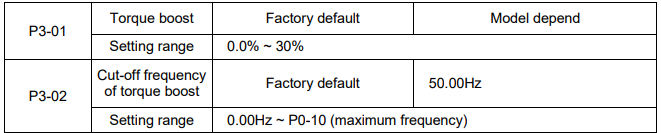
To compensate the low frequency torque characteristics of V/F control, it can boost the inverter output voltage during low frequency. If the torque boost is set to too large, the motor may be over heat, and the inverter may be over current.
Adjust this parameter according to the different loads. Increase this parameter for heavy load, reduce it for light load.
When the torque boost is set to 0.0, the inverter will adopt auto torque boost.
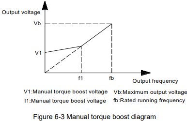
Cut-off frequency of torque boost: Under this frequency, the torque boost is valid. If it exceeds this setting frequency, the torque boost is invalid. Refer to Figure 6-3 for details.
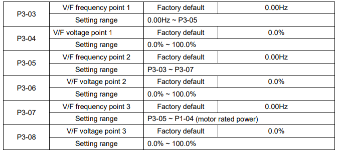
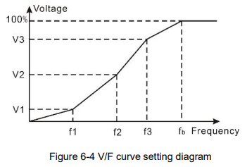
Multi-step V/F curve is defined by P3-03 to P3-08.
The curve of multi point V/F is generally set according to the load characteristics of the motor.
Caution: V1<V2<V3 and F1<F2<F3. The voltage corresponding to low frequency should not be set too high, otherwise it may cause motor overheat or inverter fault.

It is valid only for V/F control.
Setting this parameter can compensate the slip of motor speed caused by the load increases, and makes the motor speed stably when the load changes.
V/F slip compensation gain set to 100% means the slip compensation of the motor with rated load is the motor rated slip, which can be calculated according to motor rated power and motor rated speed
automatically.
Slip gain adjustment can refer to the following principle: When the load is rated load, the motor speed is basically the same as the target speed. When the values are different, please adjust this gain properly.

During deceleration, over excitation control can suppress bus voltage increase, avoid over voltage fault. The bigger over excitation gain is, the better suppression result is.
For the application which over voltage fault happens frequently during deceleration, the over excitation gain needs to be increased. But the current would be increased if the over excitation is too bigger, so you need to set the suitable over excitation gain.
For the small inertia situation, voltage doesn’t increase during motor deceleration, please set over excitation gain to 0. For the application with braking resistor, please also set over excitation gain to 0.

Set the gain as small as possible on the premise that there is effective oscillation suppression measure, which can avoid the affect causing to VF running. Set the gain to 0 when the motor has no oscillation. Only when the motor has obvious oscillation, this gain can be increased properly. The bigger the gain is, the better oscillation suppression result will be.
When using this function, please make sure the motor rated current and no load current parameters are accurate, otherwise V/F oscillation suppression result would be bad.
Group P4 Input Terminal
The standard Inverter has 7 multifunctional digital input terminals (HDI can be used as high speed pulse input terminal) and two analog input terminals.
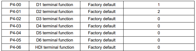
These parameters are used to set the functions of the multifunctional digital input terminals.
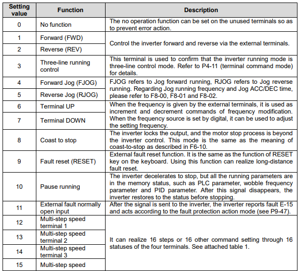
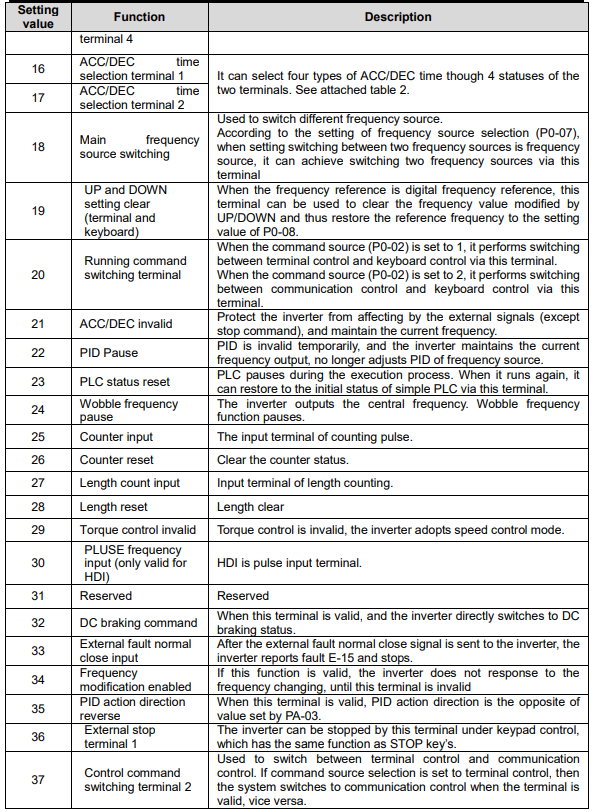
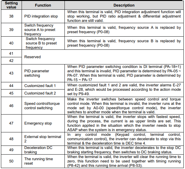
Attached Table 1 Multi-step Command Function Description
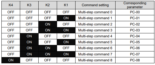
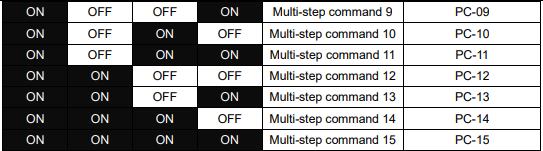
When the frequency source selection is multi-step speed, 100% of PC-00~PC-15 correspond to P0-10
(maximum frequency).
Multi-step command not only can set as multi-step speed, but also can set as PID given source, to meet the requirement of need to switch between different given values.
Attached Table 2 Multi-step Command Speed Function Description

It is used to set the sensitivity of DI terminal. If the digital input terminal is vulnerable to interferences and may cause error action, it can increase this parameter value to enhance the anti-interference capability.
However, this operation will reduce the sensitivity of DI terminal
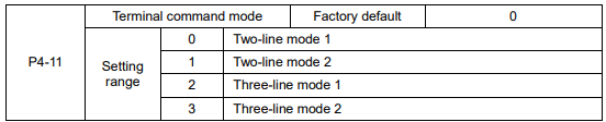
This parameter defines four different modes of controlling the operation of the inverter via the external terminals.
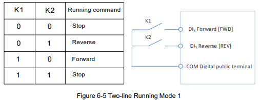
0: Two-line running mode 1: This is the most common mode. The forward/reverse rotation of the motor is decided by the commands of FWD and REV terminals.

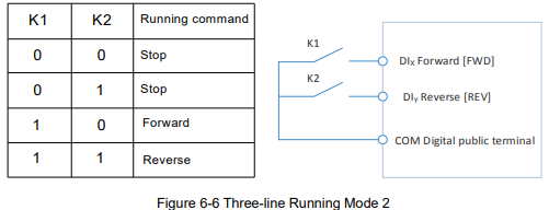
1: Two-line running mode 2: When this mode is adopted, REV is enabled terminal. The direction is determined by the status of FWD.

2: Three-line running mode 1: In this mode, DIn is enabled terminal, and the direction is controlled by FWD and REV respectively. However, the pulse is enabled through disconnecting the signal of DIn terminal when the inverter stops.

To make the inverter run, users must close DIn terminal firstly. It can achieve the motor forward or reverse control via pulse rising of DIx or DIy.
It can achieve the inverter stop via cutting off DIn terminal signal. DIx. DIy. DIn are DI1~DI6, HDI
multifunctional input terminals, the valid input of DIx (DIy) is pulses signal, and the valid input of DIn is level signal.
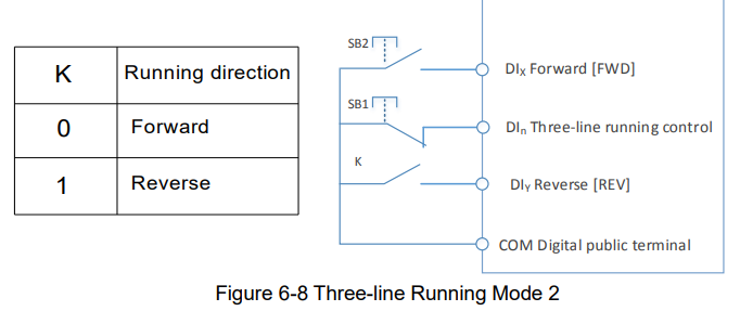
Where,
SB1: Stop button
SB2: Running button

Terminals UP/DOWN is used to adjust the change rate when setting frequency.
When P0-22 is set to 2, the range is 0.001~50.000Hz/s.
When P0-22 is set to 1, the range is 0.01~50.00Hz/s.
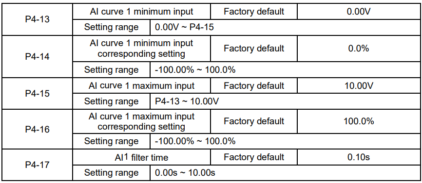
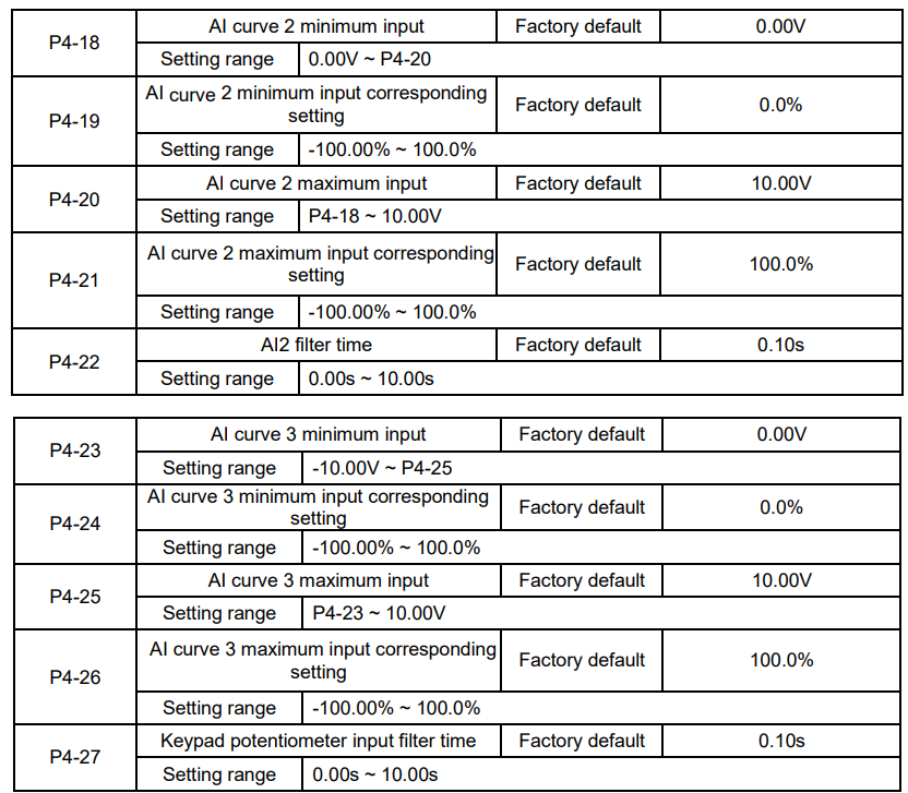
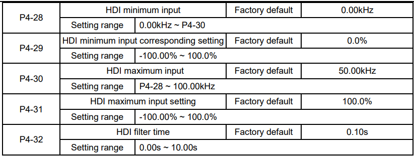
The above function codes define the relationship between the analog input voltage and analog input setting value.
When the analog input voltage is bigger than P4-15 (maximum input of AI curve 1), then calculate the analog voltage according to maximum input. When the analog input voltage is smaller than P4-13 (minimum input of AI curve 1), then calculate the analog voltage with minimum input or 0.0% according to P4-34 (AI below minimum input setting selection).
When the analog input is current input, 1mA current equals to 0.5V voltage.
AI1 input filter time is used to set AI1 software filter time, when the site analog signal can be easily
disturbed, please increase filter time to stable the detected analog signal, but the bigger the filter time is, the slower the response speed of the analog detection is . So please set this parameter according to the situation.
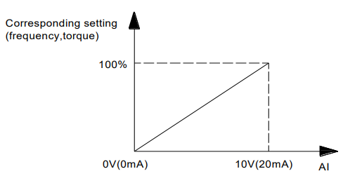
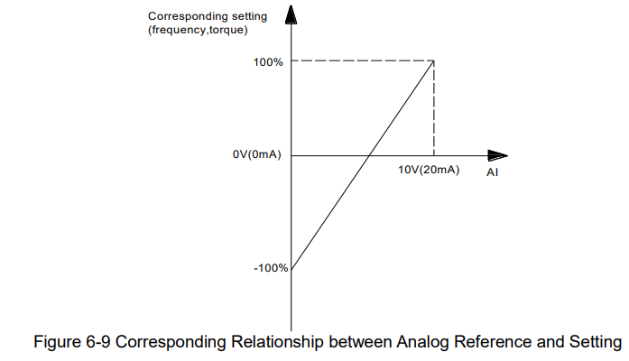
In difference applications, 100% of analog input corresponds to different nominal values. Refer to all the application parts for details.
Several setting examples are shown in the following figures:
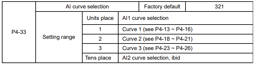
This group of function code defines the corresponding relationship when the pulse is used as frequency setting mode.
The pulse frequency input can only be input via HDI channel. The applications of this group function are similar as those of AI curve 1 function.
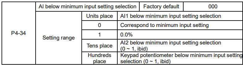
Units place and tens place of this function code are used to select analog input AI1, AI2 corresponding setting curve.
Curve 1, curve 2, curve 3 are 2 points curves, set by P4 group.
Standard inverter has 2 analog input terminals.
The parameter is used to set how to confirm the analog corresponding setting when the analog input voltage is lower than the setting “the minimum input”.
Units place, tens place and hundreds place of this function code correspond to the analog input AI1, AI2 and Keypad potentiometer.
If the selection is 0, when AI input is lower than “the minimum input”, the analog value corresponding setting is the curve “the minimum input corresponding setting” (P4-14, P4-19, P4-24) determined by the function code.
If the selection is 1, when AI input is lower than “the minimum input”, the analog value corresponding setting is 0.0%.
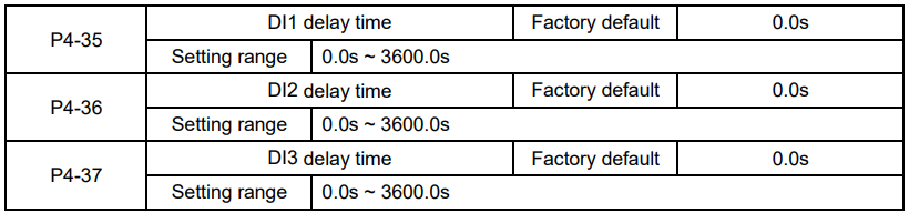
Used to set the delay time when DI terminal status changing.
Currently only DI1, DI2, DI3 have setting delay time function.
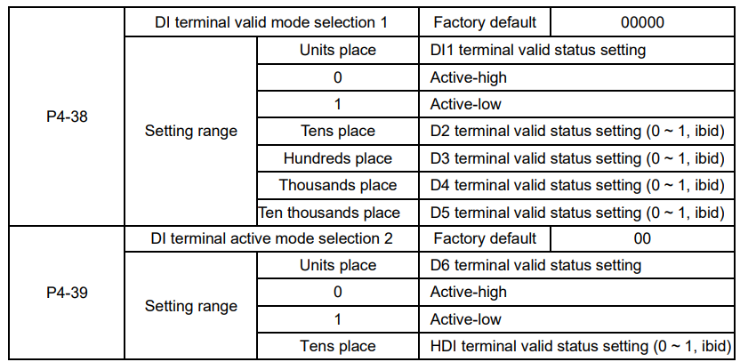
They are used to set the digital input terminal active status mode. If the selection is active-high, the relevant DI terminal connects with COM is valid, disconnect invalid. If the selection is active-high, the relevant DI terminal connects with COM is invalid, disconnect valid.
Group P5 Output Terminal
The standard Inverter has 2 multifunctional analog output terminals, 2 multifunctional relay output terminals, 1 HDO terminal (can be used as either high-speed pulse output terminal or collector open output)

HDO terminal is programmable multiplexing terminal, can be used as high-speed pulse output, with maximum frequency 100.00 kHz. Refer to P5-06 for details.

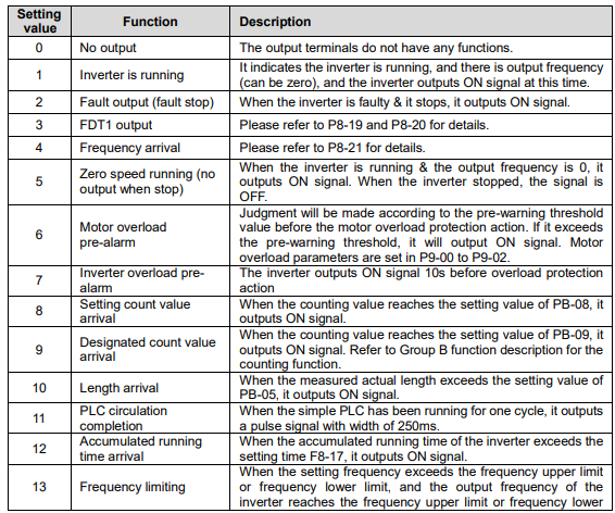
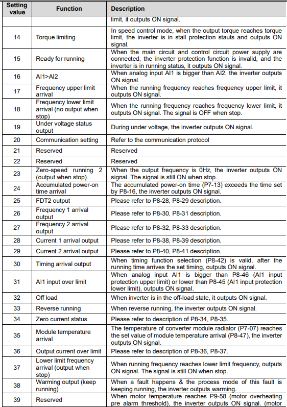
The parameters are used to select the functions of 3 digital outputs.
Multifunctional output terminal function selection is as follows:


The frequency range of HDO output pulse is 0.01 kHz ~ P5-09 (HDO maximum output frequency), P5-09 can be set between 0.01 kHz ~ 100.00 kHz.
The output range of analog output (AO1 & AO2) is 0V ~ 10V or 4mA ~ 20mA.
The corresponding value range that it indicates is shown in the table below:
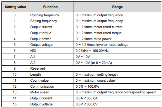

When HDO terminal is selected as pulse output, this code is used to set the maximum frequency of output pulse.
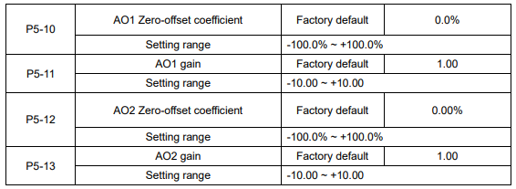
The parameters are used to correct the zero drift of the analog output and the output amplitude deviation.
They can also be used to define custom AO output curve.
If “b” represents zero offset, k represents gain, Y represents actual output, and X represents standard output, the actual output is: Y=kX+b;
Where, 100% of zero-offset coefficients of AO1 and AO2 corresponds to 10V (or 20mA).
Standard output denotes 0 to maximum analog output corresponding to the output of 0 to 10V (or 4mA to 20mA) without Zero-offset and gain correction.
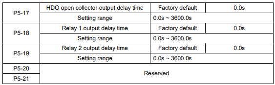
Set the delay time of output terminal HDO, relay 1 and relay 2. The delay time is time interval from the status changing to actual output changing.
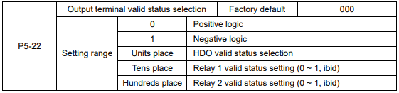
The output logic of output terminal HDO, relay 1 and relay 2.
0: Positive logic, the digital output terminal connects with the relevant COM is valid, disconnect invalid.
1: Negative logic, the digital output terminal connects with the relevant COM is invalid, disconnect valid.
Group P6 Start and Stop Control

0: Direct start
If DC braking time is set to 0, the inverter will start from the start frequency.
If DC braking time is set to nonzero value, DC braking will be performed firstly, then the inverter starts from the start frequency. It is suitable for the application that the motor maybe running during starting with small inertia load.
1: Speed tracking and restart
Inverter detects the rotation speed and direction of motor, and then starts to run at the detected speed and direction. This can realize smooth start of running motor with big inertia load when instantaneous power-off. To ensure the performance of speed tracking restart, please set motor parameters accurately. (Group P1)
2: pre-excitation start
Only valid for asynchronous motor, used to establish magnetic field before motor running. For pre-excitation current, pre-excitation time, please refer to P6-05, P6-06 instruction.
If pre-excitation time is set to 0, the inverter will cancel the pre-excitation process, start from the starting frequency. Or the inverter will make the pre-excitation, then start, which can improve the motor dynamic response performance.

To complete the speed tracking process in the shortest time, select the suitable mode of inverter tracking motor speed:
0: To track from the frequency when stop, normally it adopts this mode.
1: To track from zero-frequency, suitable for the application that restart after a long time power-off.
2: To track from maximum frequency and suitable for the general power generating loads.

It is used to select the speed tracking speed when speed tracking and restart.
The bigger this parameter is, the faster the tracking speed is. But too big value may result in unreliable tracking.

Set proper start frequency can increase the start torque.
If the reference frequency is less than start frequency, inverter will be at stand-by status, and has no output.
The start frequency could be less than the lower frequency limit.
P6-04 takes no effect during FWD/REV switching.
Example 1:
P0-03=0 Frequency source is digital reference
P0-08=2.00Hz Digital setting frequency is 2.00Hz.
P6-03=5.00Hz Start frequency is 5.00Hz.
F6-04=2.0s Start frequency holding time is 2.0s.
At this time, the inverter is at standby status, and the output frequency is 0Hz.
Example 2:
P0-03=0 Frequency source is digital setting.
P0-08=10.00Hz Digital setting frequency is10.00Hz.
P0-03=5.00Hz Start frequency is 5.00Hz.
P0-04=2.0s Start frequency holding time is 2.0s.
At this time, the inverter accelerates to 5Hz, and further to the reference frequency 10Hz in 2s
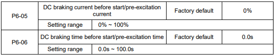
DC braking is used to make the running motor stop & restart. Pre-excitation is used to establish asynchronous motor magnetic field, then start, improve the response speed.
DC braking is only valid when start directly, the inverter performs DC braking according to P6-05 firstly, and runs after P6-06. If DC braking time is 0, the inverter starts directly. The bigger the DC braking current is, the greater the braking force is.
If the start mode is pre-excitation start, then the inverter establishes magnetic field according to the set pre-excitation current firstly, runs after the set pre-excitation time. If the pre-excitation time is 0, the inverter starts directly.
DC braking current before start/pre-excitation current refers to the percentage of the inverter rated current.

0: Linear ACC/DEC
The output frequency increases or decreases according to the straight line. KE300 series inverter has 4
kinds of ACC/DEC time, which can be set by P4-00 ~ P4-06.
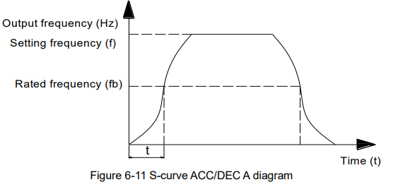
1: S-curve ACC/DEC A
The output frequency increases or decreases according to S-curve. S-curve is suitable for applications which require start & stop smoothly, such as elevator and conveyor belt.
2: S curve ACC/DEC B
In the S-curve ACC/DEC B, the motor rated frequency fb is always the inflection point of S curve, showed as figure 6-11. Suitable for the applications that the high speed area above rated frequency needs fast
ACC/DEC.
When setting frequency is above rated frequency, ACC/DEC time is:
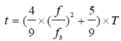
f is setting frequency, fb is motor rated frequency, T is the ACC time from 0Hz to rated frequency.

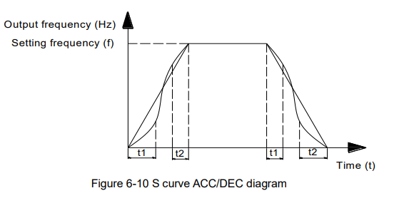
S curve start time is shown in Figure 6-10 as t1 set by P6-08, which is the stage when the slope of output frequency rises gradually.
S curve rise time is shown in Figure 6-10 as the time between t1 and t2, which is the stage when the slope of output frequency maintains phase.
S curve end time is shown in Figure 6-10 as t2 set by P6-09, which is the stage when the slope of output frequency decreases to zero

0: Deceleration to stop
After the stop command is valid, the inverter reduces the output frequency according to the DEC time and will stop after the frequency reduces to zero.
1: Coast to stop
After the stop command is valid, the inverter blocks the output immediately. The motor coasts to stop according to the mechanical inertia.
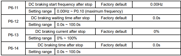
DC braking start frequency after stop: Start the DC braking when running frequency reaches this frequency determined by P6-11.
DC braking waiting time after stop: Inverter blocks the output before starting the DC braking. After this waiting time, the DC braking will be started so as to prevent over-current fault caused by DC braking at high speed.
DC brake current after stop: The value of P6-13 is the percentage of rated current of inverter. The bigger the DC braking current is, the greater the braking torque is.
DC brake time after stop: The time which is used to perform DC braking. If the time is 0, the DC braking will be invalid.
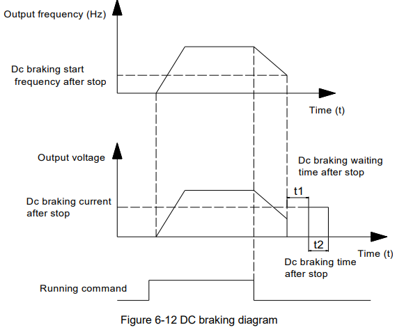

It is only valid for the inverter with built-in brake unit, can be used to adjust the braking effect of the brake unit.
Group P7 Keypad and Display

Display inverter rated power.
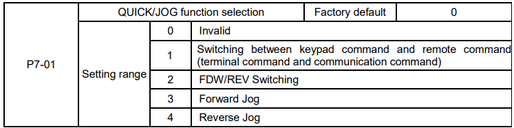
QUICK/JOG is a multifunctional key, whose function can be defined by the value
0: This key is invalid
1: Switching between keyboard command and remote operation. It refers to switching of command source, switching between the current command source and the keyboard control (local operation). If the current command source is keyboard control, this key is invalid.
2: Press QUICK/JOG, the running direction of inverter will change. It is only valid when keypad command is valid.
3: It can realize forward jog via QUICK/JOG key.
4: It can realize reverse jog via QUICK/JOG key.

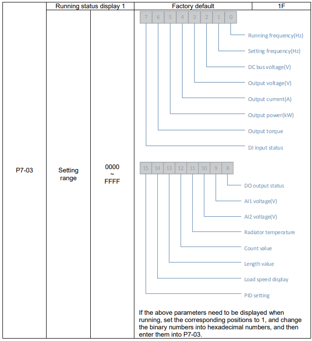
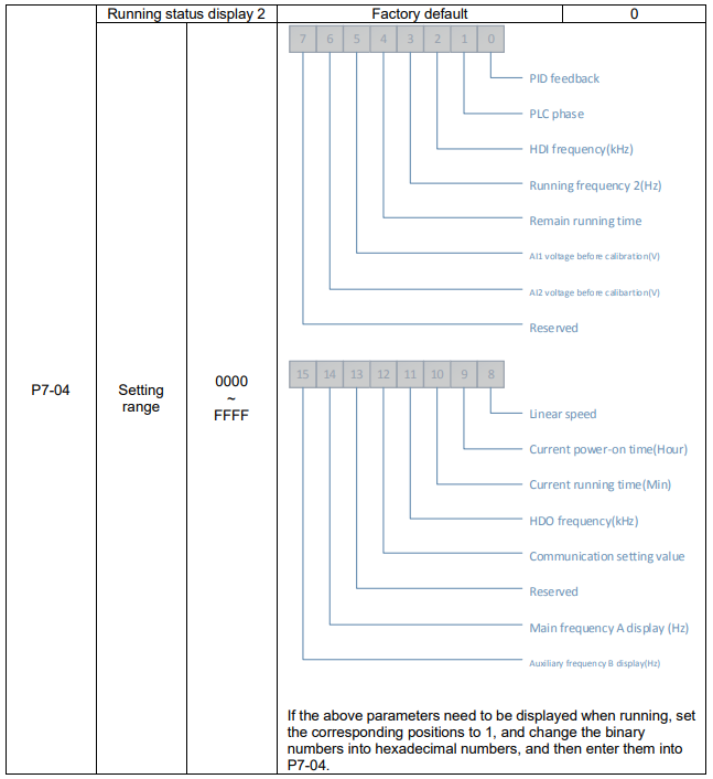
Operation display parameter is used to set the parameters which can be viewed when running.
There are at most 32 parameters can be viewed, set the status parameters via the binary bits of P7-03 and P7-04, and the display sequence starts from the lowest order of P7-03.
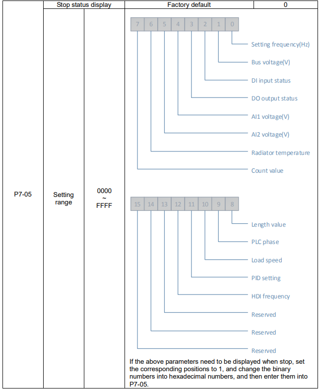

The correspondence of the inverter output frequency and the load speed can be adjusted via this parameter when the load speed needs to be displayed.

Display IGBT module temperature.
The over temperature protection values of different IGBT modules are not the same.

Display inverter rated voltage

Display the accumulated running time of the inverter. When the running time reaches the value set by P8-17, the digital output terminal outputs ON signal.
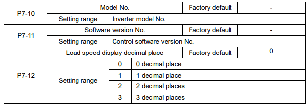
The parameters are used to set load speed display decimal place. The following load speed calculation format for example:
If load speed display factor (P7-06) is 2.000, load speed decimal place (P7-12) is 2 (2 decimal places), when the running frequency is 40.00Hz, load speed is: 40.00×2.000=80.00 (2 decimal places displayed)
If the inverter stops, load speed is displayed as setting frequency corresponding speed, namely “setting load speed”. If setting frequency=50.00Hz, the stop status load speed is: 50.00×2.000=100.00 (2 decimal places displayed)

Display the accumulated power-on time after production.
When this time reaches the value set by P8-17, the inverter multifunctional digital output function (24) outputs ON signal.

Display the accumulated power consumption till now.
Group P8 Enhanced Function
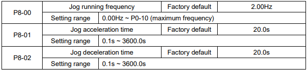
It is used to define the reference frequency and ACC/DEC time of the inverter when jogging. During Jog running, the start mode is fixed to direct start (P6-00=0), the stop mode is fixed to deceleration to stop (P6-10=0).
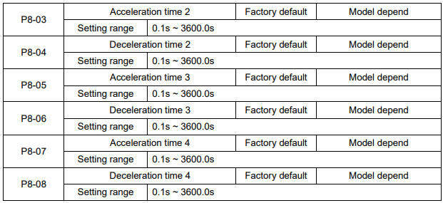
KE300 series inverter supplies 4 kinds of ACC/DEC time. The principles of them are the same. Please refer to description of P0-17 and P0-18 for more details.
User can select the one of 4 kinds ACC/DEC time thought the different combination of DI terminals. See the description of P4-00~P4-05, then pay attention to Function (16) & Function (17) and Attached table 2.
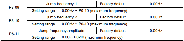
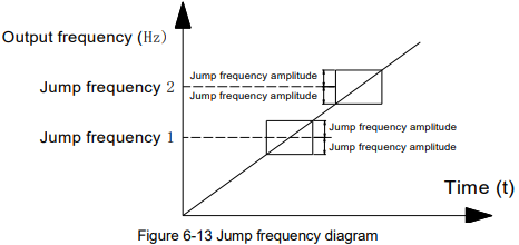
By means of setting jump frequency, the inverter can keep away from the mechanical resonance with the load. P8.09 and P8.10 are center value of frequency to be skipped.
If both P8-09 and P8-10 are 0, the jump frequency function is invalid no matter what P8.11 is.

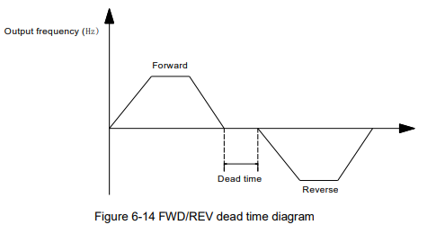
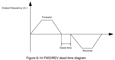
FWD/REV dead time: The waiting and holding time before the motor changes its spinning direction after the inverter's output frequency is decreased to zero. It is the time taken by the motor to change its spinning direction when the inverter receives REV command during its running process. The time is shown in Figure 6-14:

FWD/REV dead time: The waiting and holding time before the motor changes its spinning direction after the inverter's output frequency is decreased to zero. It is the time taken by the motor to change its spinning direction when the inverter receives REV command during its running process. The time is shown in Figure 6-14:

It is used to set if the inverter can run reverse, P8-13 is set to 1 for the applications that the motor can not run reverse.

It is used to select the inverter running status when the setting frequency is lower than the frequency lower limit.

When several motors drive the same load, each motor's load is different because of the difference of motor's rated speed. The load of different motors can be balanced through droop control function which makes the speed droop along with load increase.
When the motor outputs rated torque, actual frequency drop is equal to P8-15. User can adjust this parameter from small to big gradually during commissioning.

When the accumulated power on time (P7-13) reaches the value set by P8-16, the multifunctional digital DO outputs ON signal.

It is used to set the running time of the inverter.
When the accumulated running time (P7-09) reaches the value set by P8-17, the multifunctional digital DO outputs ON signal.

1. If power-on running command is valid (for example, the terminal running command is close before power on), the inverter will not response the running command. After the running command is removed & valid again, the inverter will response.
2. If the fault reset running command is valid, the inverter will not response the running commend, user must cancel the running command to remove the running protection status.
3. This code is set to 1 so as to avoid dangerous caused by that motor responses running command during power-on or fault reset.

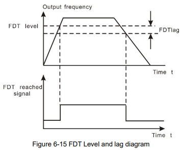
When the output frequency reaches a certain preset frequency (FDT level), DO terminal will output an ON signal until output frequency drops below a certain frequency of FDT level (FDT level - FDT lag), as shown in following figure.

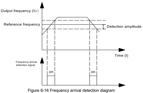
When output frequency is within the detecting range of reference frequency, an ON-OFF signal will be output. The function can adjust the detecting range.

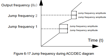
It is used to set if jump frequency is valid during ACC/DEC.
When valid, the running frequency is in the range of jump frequency, the actual running frequency will skip the boundary of the setting jump frequency.
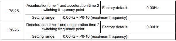
This function is valid when don’t use DI terminal to switch ACC/DEC. Suitable for the inverter running process, choose different ACC/DEC time according to the running frequency range (instead of through DI terminals).
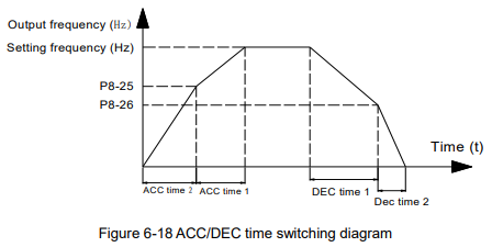
During ACC, if the running frequency is lower than P8-25, then select ACC time 2, if the running frequency is higher than P8-25, then select ACC time 1.
During DEC, if the running frequency is higher than P8-26, then select DEC time 1, if the running frequency is lower than P8-26, then select DEC time 2.

It is used to set whether the priority of terminal jog function is the highest.
When terminal jog priority is valid, if terminal jog command appears when running, the inverter switches to terminal jog running status.

This frequency detection function is the same as FDT1’s, please refer to description of FDT1 (P8-19, P8-20).
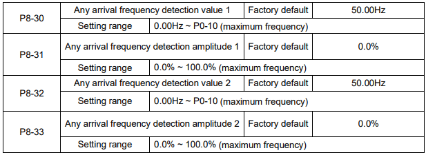
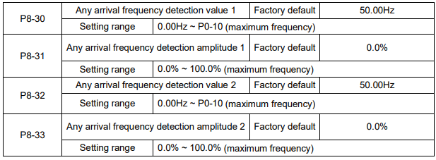
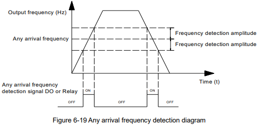
When the output frequency reaches positive or negative detection amplitude of frequency detection value, DO outputs ON signal. KE300 series inverter provides two parameters of any arrival frequency detection value, used to set frequency value and frequency detection range.

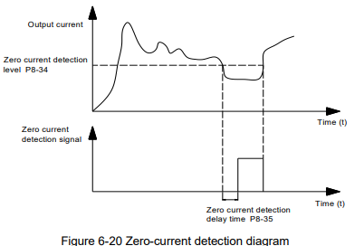
When the output current ≤ zero current detection level, lasts for longer than zero current detection delay time, DO terminal outputs ON signal.
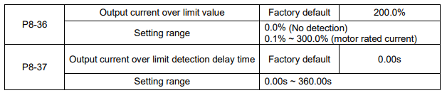
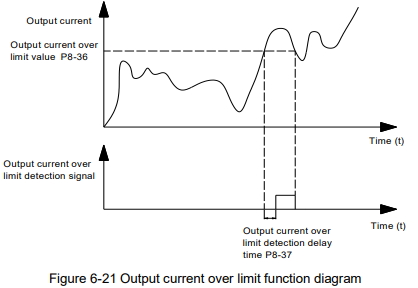
When the output current is bigger than or over-limit detection point, lasts for longer than software over current point detection delay time, DO terminal outputs ON signal.


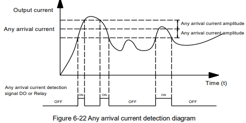
When the output current is in the range of positive or negative detection amplitude of setting any arrival current, DO terminal outputs ON signal. KE300 series inverter provides two parameters of any arrival current and detection amplitude.
The parameters are used to set the inverter timing running function.
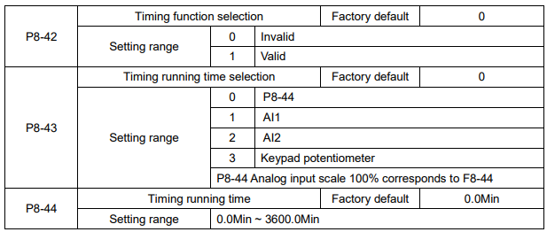
When P8-42 timing function selection is valid, timing starts after the inverter starts, reaches the setting timing running time, the inverter stops automatically, meantime, DO terminal outputs ON signal.
Timing starts from 0 when the inverter starts, timing remain running time can be viewed via U0-20.
The timing running time is set by P8-43, P8-44, time unit is minute.

When the analog input AI1 value is bigger than P8-46, or smaller than P8-45, DO terminal outputs “AI1 input over limit” ON signal, used to indicate whether AI1 input voltage is in the setting range.

When the converter radiator temperature reaches this value, DO outputs “module temperature arrival” ON signal.

It is used to select cooling fan action mode,
When the selection is 0, cooling fans run when the inverter running, when the inverter stops & the radiator temperature is higher than 40℃, cooling fans run.
When the inverter stops & the radiator temperature is lower than 40℃, cooling fans stop.
When the selection is 1, cooling fans always run after power-on.
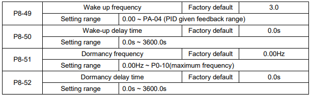
The parameters are used to achieve dormancy and wake up function in water-supply applications.
During running, when the setting frequency ≤ P8-51 dormancy frequency, lasts for P8-52 delay time, the inverter enters into dormancy status & stops automatically.
When the inverter is in the dormancy status & the present running command is valid, if the setting frequency ≥ P8-49 wake up frequency lasts for P8-50 delay time, the inverter starts.
Normally please set wake up frequency ≥ dormancy frequency. Setting both wake up frequency and dormancy frequency are 0.00Hz, then wake up and dormancy functions are invalid.
When starting dormancy function, if frequency source is set by PID, PA-28 will affect whether dormancy status PID calculates or not, PID stop calculation function must be set to be 1 (namely PA-28=1).

When the running time reaches the time set by P8-53, DO outputs “Running arrival time setting” ON signal.
Group P9 Fault and Protection

P9-00=0: Has no motor overload protection function, may cause the motor overheating damaged.
P9-00=1: The inverter judges whether the motor is overload or not according to the inverse time limit curve of motor overload protection.
The inverse time limit curve of motor overload protection: 220%×(P9-01)×motor rated current, lasts for one minute, the overload fault would be reported; 150%×(P9-01)×motor rated current, lasts for 60 minutes, the overload fault would be reported.
Please set P9-01 according to the motor overload ability. If the parameter is too big, the motor will over heat damage without alarming.

For safe consideration, there is a pre-warming signal sent to the control system via DO before the motor overload fault protection, the pre-warming coefficient is used to confirm the extent of pre-warming before the motor overload protection. The bigger the parameter is, the smaller the pre-warming lead is.
After the accumulated output current is bigger than (P9-02)*overload inverse time limit curve, DO outputs “motor overload pre-warming” ON signal.

During deceleration, after DC bus voltage exceeds over-voltage stall protection voltage, the inverter stops deceleration & runs with the current frequency, continue decelerating after bus voltage drops.
Over-voltage stall gain is used to adjust the suppression over-voltage capacity during deceleration. The bigger this value is, the stronger the capacity is. Under the precondition of no over-voltage, please set the gain as small as possible.
For the load with small inertia, the value should be small. Otherwise, the dynamic response of the system will be slow. For the load with big inertia, the value should be big. Otherwise, the suppression result will be poor, and over voltage fault may occur.
When the value is 0, the over voltage stall function is invalid.

During the inverter ACC/DEC, when the output current exceeds over-current stall protection current, the inverter stops ACC/DEC, runs with the current frequency, continue ACC/DEC after the output current is reduced.
Over-current stall gain is used to adjust the suppression over-current capacity during ACC/DEC. The bigger this value is, the stronger the capacity is. Under the precondition of no over-current, please set the gain as small as possible.
For the load with small inertia, the value should be small. Otherwise, the dynamic response of the system will be slow. For the load with big inertia, the value should be big. Otherwise, the suppression result will be poor, and over-current fault may occur.
When the value is 0, the over-voltage stall function is invalid.

It is used to check if the motor is short circuit to ground when the inverter is power on.
If the function is valid, the inverter UVW terminals have output voltage after power on for a while.
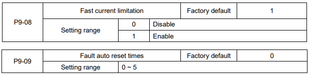
After the inverter fails in running process, the inverter stops its output; then performs auto fault reset and continues running after the reset interval defined in P9-11.
P9-09 is used to set fault auto reset times. After this value is exceeded, the inverter will keep fault status.
When the fault auto reset time is setup to 0, there is no auto-reset function, and only manual reset can be done.

If fault auto reset function is valid, during fault auto resetting, fault reply action or not can be set via P9-10.

The waiting time of the inverter from the fault alarm to auto reset.

KE300 series inverter has no input phase failure protection function at present, whatever P9-12 is set to 0 or 1, this function is invalid.

Select to protect output phase failure or not.

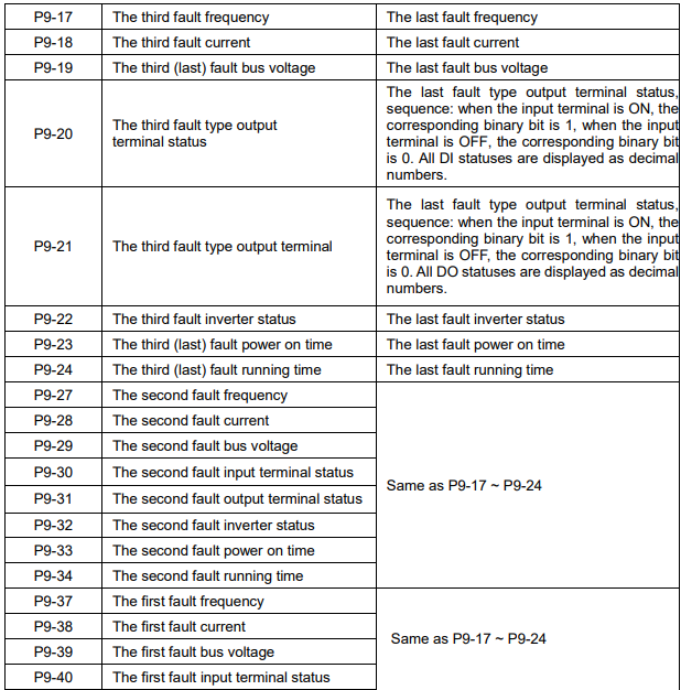
It is used to record the fault types of last three times: 0 indicates no fault, please refer to Chapter 8 for solutions.

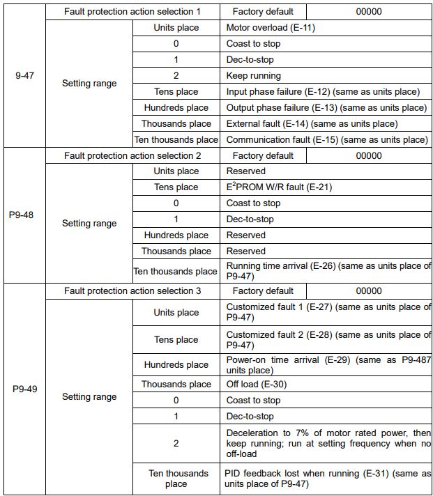
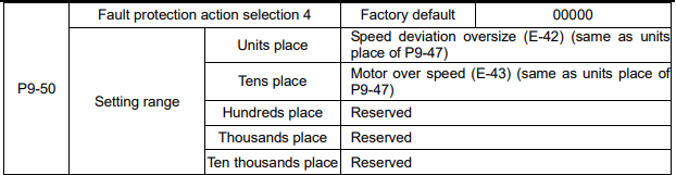
When the selection is “Coast to stop”, the inverter shows E-** and stops directly.
When the selection is “Dec- to-stop”, the inverter shows A-** and decelerates to stop, then shows E-** after stopping.
When the selection is “keep running”, the inverter shows A-** and keeps running, the running frequency is set by P9-54.
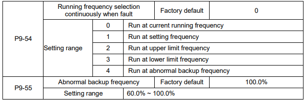
When a fault happens during running and the fault process mode is keep running, the inverter shows A-** with the frequency set by P9-54.
When the inverter is running with the abnormal backup frequency, the value set by P9-55 corresponds to maximum frequency percentage.
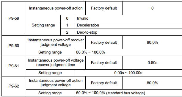
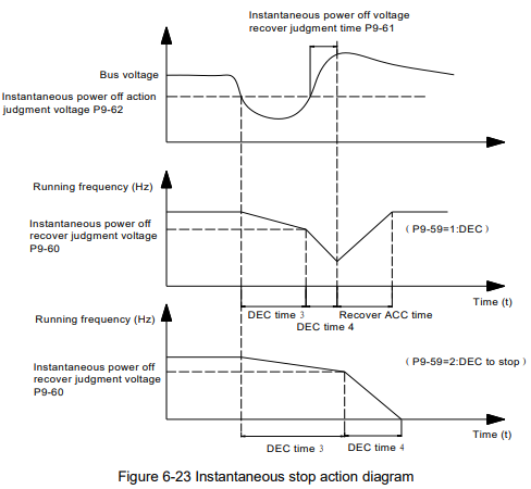
The function is that, when instantaneous power off or voltage drops suddenly, the inverter will reduce output speed to decrease compensation voltage for DC bus which is generated by the load feedback energy, so that keep the inverter running.
P9-59=1: When instantaneous power off or voltage drops suddenly, the inverter decelerates, when bus voltage returns to normal, the inverter accelerates to the setting frequency and runs. Normal bus voltage lasts for longer than the time set by P9-61 means that bus voltage returns to normal.
P9-59=2: When instantaneous power off or voltage drops suddenly, the inverter decelerates to stop.
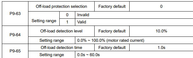
If off-load protection function is valid, when the output current is smaller than off-load detection level P9-64, lasts for longer than off-load detection time P9-65, the output frequency will reduce to 7% of the rated frequency automatically. During off-load protection, if load recovers, the inverter will recover and run with the setting frequency automatically
Group PA PID Function
PID control is a common used method in process control, such as flow, pressure and temperature control.
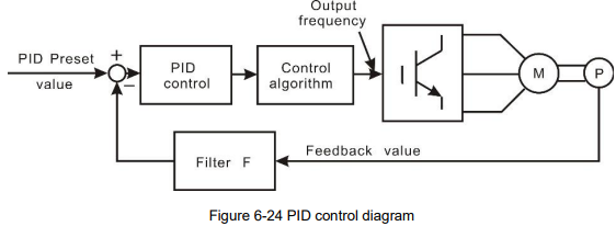
The principle is firstly to detect the bias between preset/given value and feedback value, then calculate output frequency of inverter according to proportional gain, integral and differential time. Please refer to following figure.
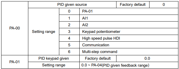
This parameter is used to select the given channel of PID target value
This value is an actual physical quantity. It must correspond to the measure range. For example, if the PID keypad given value is 0.3Mpa, PA-01 should be set to 3.0.
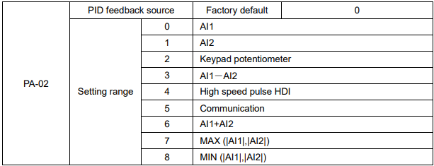
These parameters are used to select PID given and feedback source.
Notice: Given value and feedback value of PID are percentage values.
100% of given value is corresponding to 100% of feedback value.
Given source and feedback source must not be same, otherwise PID will be malfunction.

0: Positive. When the feedback value is greater than the given value, output frequency will be decreased, such as tension control in winding application.
1: Negative. When the feedback value is greater than the given value, output frequency will be increased, such as tension control in unwinding application.

PID given feedback range is a non-dimensional unit. It must correspond to the actual measure range. For example, if the measure range of the pressure meter is 1.0 Mpa, then this parameter should be set to 10.
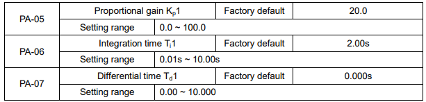
Proportional gain Kp1: It decides the adjustment intensity of the whole PID regulator. The higher the Kp1 is, the stronger the adjustment intensity is. When this parameter is 100, indicating the deviation between PID feedback value and given value is 100%, the adjustment amplitude of the PID regulator on the output frequency command is maximum frequency.
Integration time Ti1: It decides the intensity of the integration adjustment of PID regulator. The shorter the integration time is, the stronger the adjustment intensity is. Integration time is the time within which the adjustment value reaches maximum frequency when the deviation between PID feedback value and given value is 100%.
Differential time Td1: It decides the intensity of the deviation change rate of PID regulator. The longer the differential time is, the stronger the adjustment intensity is. Differential time is the time within which if the feedback value changes 100%, the adjustment value reaches maximum frequency

In some situation, only when PID output frequency is negative (inverter reverse), PID can make given value and feedback value in a same status. But the reverse frequency cannot be too high for some applications. The reverse frequency upper limit is determined by PA-08.

When the deviation between PID given value and feedback value is smaller than PA-09, PID stops adjustment. The output frequency is stable when the deviation is small, which is suitable for some close loop control applications.

PID given filter time is the time that PID given value changes from 0.0% to 100.0%.
When PID given is changing, PID given value linearly changes according to the given filter time, so as to reduce the adverse effect of the system caused by the given sudden change.

PA-12 is used to filter the PID feedback value, this filter can improve anti-interference capability of feedback value, but will bring the response performance of the process close loop system down.
PA-13 is used to filter the PID output frequency, this filter will reduce the sudden change of the inverter output frequency, but also will bring the response performance of the process close loop system down
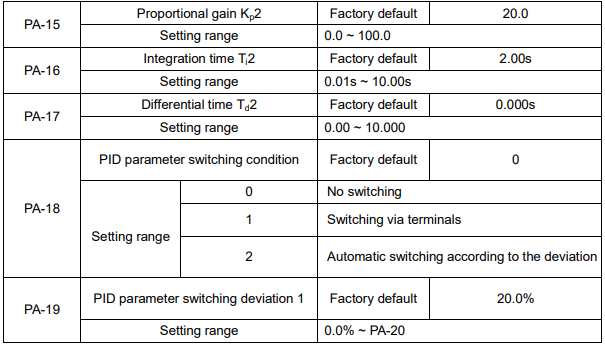

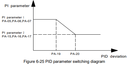
In some applications, one group PID parameter is not enough, different PID parameters would be adopted according to the situation.
The function codes are used to switch two groups PID parameter. The setting mode of the regulator parameters PA-15~PA-17 is similar as PA-05~PA-07’s.
Two groups PID parameter can be switched via DI terminal, or switched according to PID deviation automatically.
When selection is automatic switching: when the deviation absolute value between given and feedback is smaller than PA-19 (PID parameter switching deviation 1), PID parameter selection is group 1. When the deviation absolute value between given and feedback is bigger than PA-20 (PID parameter switching deviation 2), PID parameter selection is group 2. When the deviation absolute value between given and feedback is between PA-19 and PA-20, PID parameter is the linear interpolation of two groups PID parameter, showed as figure 6-25.

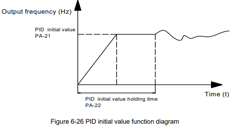
When starting, PID output is PID initial value (PA-21), lasts for PID initial value holding time (PA-22), PID starts close-loop regulate calculating

This function is used to limit the difference between PID output two bats (2ms/bat), so as to against PID output changing too fast, make the inverter run stably.
PA-23 and PA-24 correspond to the maximum of the output deviation absolute value when forward and reverse, respectively.
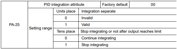
Integration separation:
If integration separation is valid, when multifunctional digital DI integration pause (function 22) is valid, PID integration stop calculating, PID is only valid when proportional and differential action.
When integration separation is invalid, whatever multifunctional digital DI is valid or not, integration separation is invalid.
Stop integrating or not after output reach limit:
After PID calculation output reaches the maximum or minimum, whether stop integral action or not can be selected. If the selection is stop integrating, PID integration will stop calculating, which may help to reduce PID overshoot.

The parameters are used to judge whether PID feedback lost or not.
When PID feedback is smaller than feedback lost detection value (PA-26), lasts for longer than PID feedback lost detection time (PA-27), the inverter alarms fault E-31, and handles according to the chose fault process mode.

This parameter is used to select PID stop status & whether PID continues calculating or not. For normal applications, PID should stop calculating when stop
Group PB Wobble Frequency, Fixed Length, Counting
The wobble frequency function is suitable for textile, chemical fiber industries, and the applications which require traversing and winding functions.
The wobble frequency function means that the output frequency of the inverter wobbles up and down with the setting frequency as the center. The trace of running frequency at the time axis is shown in the figure below, of which the wobble amplitude is set by PB-00 and PB-01. When PB-01 is set to 0, indicating the wobble amplitude is 0, the wobble frequency is disabled.
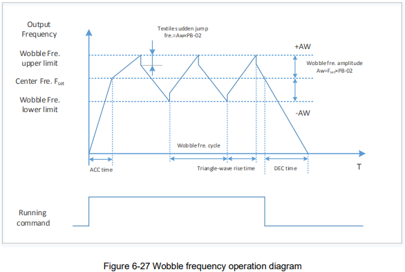

This parameter is used to select the reference value of the wobble amplitude.
0: Relative to the center frequency (P0-07: frequency source selection), and it is variable wobble amplitude system. The wobble amplitude changes with the center frequency (setting frequency).
1: Relative to the maximum frequency (P0-10) and it is fixed wobble amplitude system. The wobble amplitude is fixed.

This parameter is used to determine the values of wobble amplitude and sudden jump frequency. The wobble frequency is limited by the frequency upper limit and frequency lower limit.
The wobble amplitude is relative to the central frequency (variable wobble amplitude, select FB-00=0):
wobble amplitude: AW=frequency source: F0-07 × wobble amplitude: FB-01.
The wobble amplitude is relative to the maximum frequency (fixed wobble amplitude, select FB-00=1):
wobble amplitude: AW=maximum frequency: F0-10 × wobble amplitude: FB-01.
Sudden jump frequency=wobble amplitude: AW × sudden jump frequency amplitude: FB-02. That is the value of sudden jump frequency relative to the wobble amplitude when the wobble frequency is running.
If the wobble amplitude relative to the central frequency (variable wobble amplitude, select FB-00=0) is selected, the sudden jump frequency is a variable value.
If the wobble amplitude relative to the maximum frequency (fixed wobble amplitude, select FB-00=1) is selected, the sudden jump frequency is a fixed value.

Wobble frequency cycle: It refers to the time of a complete cycle of wobble frequency.
PB-04 is relative to the percentage of PB-03.
Triangular wave rise time = PB-03 × PB-04 (unit: s)
Triangular wave fall time = PB-03 × (1-PB-04) (unit: s)
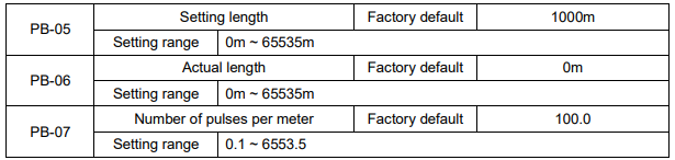
The parameters are used in fixed length control.
Length information can be collected via input terminals, PB-06= the collected number of pulses/PB 07.
When PB-06 is longer than PB-05, DO outputs “length arrival” ON signal.
During fixed length control, length reset operation can be done by set DI terminal function to 28, refers to P4-00~P4-06 for details.
The relative input terminal function need to be set to 27 (length counting input) for applications, HDI must be used when the pulse frequency is high.

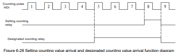
The counting value can be collected via digital input terminals. The relative input terminal function need to be set to 25 (Counter input) for applications, HDI must be used when the pulse frequency is high.
When the counting value reaches PB-08, DO outputs “setting counting value arrival” ON signal, then the counter will stop counting.
When the counting value reaches PB-09, DO outputs “designated counting value” ON signal. The counter will continue counting till the “setting counting value” is reached.
PB-09 should not exceed PB-08.
Group PC Multi-step Command and Simple PLC Function
The multi-step command of KE300 series inverter has more functions than normal multi-step speed.
Besides multi-step speed functions, it can be used as the given source of the process PID.
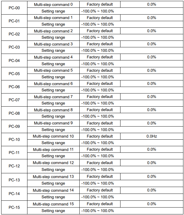
Multi-step command can be used in two situations: as frequency source or as the setting source of the process PID.
In two situations, the dimension of the multi-step command is relative value, range -100.0%~100.0%,
When as the frequency source is the percentage of the relative maximum frequency, multi-step command as PID setting source does not need dimension switching, because PID given is relative value. Multi-step command switches selection according to the different status of multifunctional digital D, please refer to P4 group for details.

When frequency source is set by simple PLC, the symbols of PC-00 ~ PC-15 determines the running direction, the inverter run reverse if they are negative values.
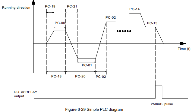
0: Stop after one cycle: Inverter stops automatically as soon as it completes one cycle, and It needs run command to start again.
1: keep last frequency after one cycle: Inverter holds frequency and direction of last phase after one cycle.
2: Circular running: Inverter continues to run cycle by cycle until receive a stop command.
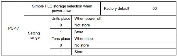
PLC storage when power-off means the last PLC running phase and running frequency are memorized before power-off, keep running from the memory status after power-on next time.
When selection is “not store”, restart PLC process after power-on each time.
“PLC storage when stop” means the last PLC running phase and running frequency are memorized when stopping, keep running with the memory status after power-on next time. When selection is “not store”, restart PLC process after power-on each time.
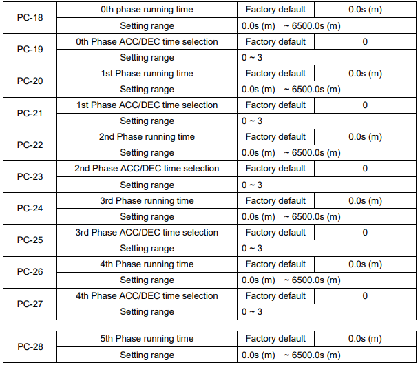
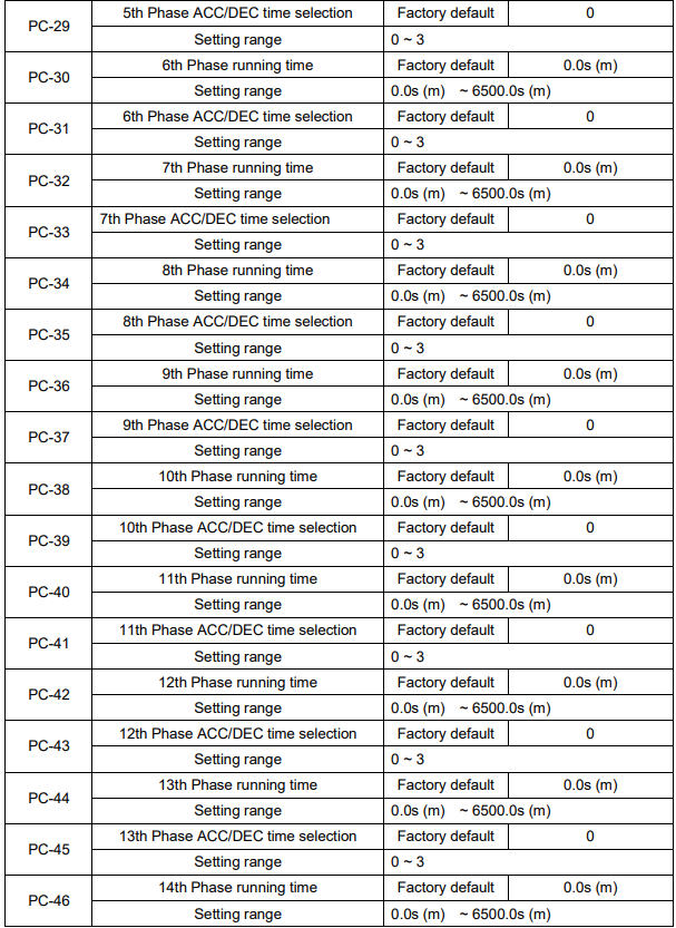
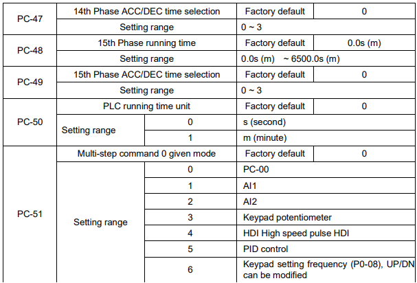
The given channel of multi-step command 0 is determined by this parameter.
Multi-step command 0 has many selections besides PC-00, which is conveniently for switching between multi-step command and other given modes. When the frequency source is set by multi-step command or simple PLC, it can achieve switching two frequency sources easily.
Group PD Communication Parameters
Refer to the Communication Protocol for details.
Group PP Function Code Management

Any non-zero number can be set, and then the password protection function will be enabled. When user enters into the menu next time, “-----” will be displayed, please input the right password, otherwise the parameters cannot be checked or modified.
0000: Clear the previous password and disable the password protection function.

1. Restore to factory default, but not including motor parameters.
After PP-01 is set to 1, most of the inverter function parameters are restored to the factory default settings, except motor parameters, frequency command decimal place (P0-22), fault record information, accumulated running time (P7-09), accumulated power on time (P7-13), accumulated power consumption (P7-14).
2. Clear the record information.
Clear the fault record information, accumulated running time (P7-09), accumulated power on time (P7-13), accumulated power consumption (P7-14).
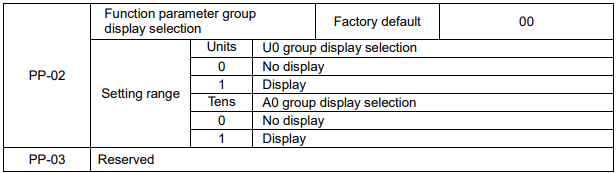
The setting of parameter display mode is convenient for users to view the function parameter of different spread patterns according to the actual demand.

The customer setting function code parameter can be modified or not, is used to protect function parameter being modified improperly.
When the function code is set to 0, all the function codes can be modified, when the function code is set to 1, all the function codes only can be viewed, but not modified.
Group A0 Torque Control Parameters
A0 group defaults to the hidden parameter group, the display attribute of A0 group can be modified via setting PP-02, please refer to PP-02 for details.

It is used to select the inverter control mode: speed control or torque control.
P0-01 (control mode) must be set to 1 (sensorless vector control) if you need to use torque control.
Multifunctional digital DI terminal has two functions related with torque control: torque control prohibit (function 29), speed control/torque control switching (function 46). The two terminals need to be matched up with A0-00 to switch speed control and torque control.
When speed control/torque control switching terminal is invalid, the control mode is determined by A0-00.
When speed control/torque control switching terminal is valid, the control mode is determined by A0 00 value reverse.
When torque control prohibit terminal is valid, the control mode is speed control.
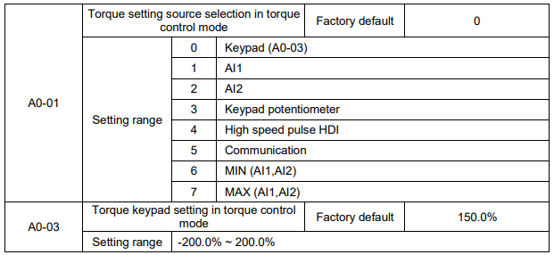
A0-01 is used to select torque setting source including 8 torque setting mode.
Torque setting adopts relative value, 100.0% corresponds to the rated torque, range: -200.0%~200.0%, means the maximum torque is 2 times rated torque.
When torque setting is 1~7, 100% of communication, analog input, pulse input corresponds to A0-03

Torque filter time is used to set torque software filter time, when the rapid torque response is needed, please reduce torque filter time. When the smooth torque control is needed, please increase the torque filter time. And the longer filter time is, the slower torque response is.
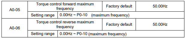
It is used to set forward or reverse maximum running frequency in torque control.
When torque control, if the load torque is smaller than the motor output torque, the motor speed will
increase, and the motor maximum speed should be limited to protect mechanical system from galloping or other accidents.

The speed variation rate of the motor and load is determined by the difference between the motor output torque and the load torque in torque control mode. So the motor speed may change rapidly, and causes noise or mechanical stress too big, etc. The motor speed can change smoothly via setting torque control ACC/DEC time.
Torque control ACC/DEC time should be set to 0.00s for the application which needs torque responding rapidly.
For example: two motors drag one load by hard wiring, to make sure uniform distribution of loading, one inverter is set to the master & adopts speed control mode, the other is set to the slave & adopts torque control. The torque command of the slave is set to the actual output torque of the master, the slave torque needs to follow the master rapidly, then the torque control ACC/DEC time should be set to 0.00s.
Group U0 Monitoring Parameters
For the convenience of the field debugging, U0 group indicates running status of inverter. User can view them on the keypad.

U0-00 displays absolute value of theoretical running frequency of the inverter.
U0-01 displays absolute value of setting frequency of the inverter.
The actual output frequency of inverter refers to U0-19.

U0-02 displays the voltage of DC bus.

U0-03 displays the output voltage of inverter at run time.

U0-04 displays the output current of inverter at run time.

U0-05 displays the output power of inverter at run time.

U0-06 displays the output torque of inverter at run time

U0-07 displays the digital value Input terminal state which can be expressed by a 8-bit binary code; if the inverter detects that the input of corresponding terminal is high level(closed), then this bit is set to "1", if the input of corresponding terminal is low level(open), then the bit is set to "0". The relationship between Digital value Input terminal and binary code is shown below.


U0-07 displays the digital value output terminal state which can be expressed by a 8-bit binary code; if the inverter detects that the output of corresponding terminal is high level (closed), then this bit is set to "1", if the output of corresponding terminal is low level (open), then the bit is set to "0". The relationship between Digital value output terminal and binary code is shown below.


U0-09 displays the input voltage of AI1.

U0-10 displays the input voltage of AI2.

U0-11 displays the current temperature of radiator.

U0-12 displays the current value of counter.

U0-13 displays the current value of length.

U0-14 displays the speed of load. Refer to the description of P7-12 in user manual.

U0-15 displays the setting value of PID.
U0-16 displays the feedback value of PID.
Take the following formulas as follows:
The setting value of PID= the setting (percentage) of PID × PA-04
The feedback value of PID=the feedback (percentage) of PID × PA-04

U0-14 displays the current step when inverter is running in simple PLC mode.
The relationship between displayed value and current step is shown below.


U0-18 displays the sampling frequency of High-speed-pulse input (HDI). The smallest unit is 0.01 KHz.

U0-19 displays the actual output frequency of inverter:
When P0-22 is set to 1, the range is -3200.0 to 3200.0. (Unit: Hz)
When P0-22 is set to 2, the range is -320.00 to 320.00. (Unit: Hz)

U0-20 displays remain running time when inverter is running at timing running mode. (Refer to P8-42, P8-43 and P8-44).
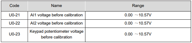
U0-21 displays the sampling voltage of analog input 1(AI1).
U0-22 displays the sampling voltage of analog input 2(AI2).
The actual input voltage is corrected value after linear calibration, so as to reduce the deviation between sampling voltage and the actual input voltage.
U0-09 and U0-10 display the actual voltages.

U0-24 displays the sampling linear velocity of High-speed-pulse input (HDI). The unit is meter per minute (m/min).
It can be calculated according to number of the actual sampling pulse and PB-07(number of pulse per meter).

U0-27 displays the sampling frequency of High-speed-pulse input (HDI). The unit is 1 Hz. Actually, U0-27 displays the same data with U0-18. The only difference is the unit.

U0-28 displays the data written to address 0X1000.


U0-30 displays the frequency of main reference-input-channel (Refer to P0-03).
When P0-22 is set to 1, the range is -3200.0 to 3200.0 (Unit: Hz).
When P0-22 is set to 2, the range is -320.00 to 320.00 (Unit: Hz).

U0-31 displays the frequency of auxiliary reference-input-channel (Refer to P0-04).
When P0-22 is set to 1, the range is -3200.0 to 3200.0 (Unit: Hz).
When P0-22 is set to 2, the range is -320.00 to 320.00 (Unit: Hz).


U0-43 displays the current temperature of motor.
NOTE: This code is reserved (not available in present).

U0-43 displays the current upper limit setting of torque. Refer to P2-09 and P2-10


U0-43 displays the current power factor angle.

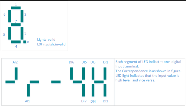
U0-41 displays the input terminal state on the keypad intuitively.
Take the description for reference:

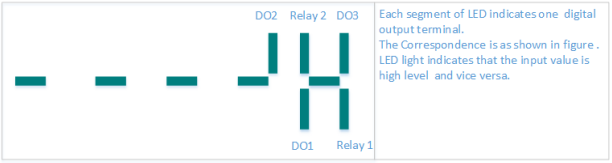
U0-42 displays the digital value output terminal state on the keypad intuitively

U0-43 displays whether intuitive display function 1-40 are valid or not.
There are 5 digital tubes on keypad. Every digital tube has 8 segments, and each segment indicates a certain function selection.
Define digital tube as shown in figure.
Digital tubes from left to right represent intuitive display function 1-8, 9-16, 7-24, 25-32, 33-40.

U0-44 displays whether intuitive display function 41-59 are valid or not.
There are 5 digital tubes on keypad. Every digital tube has 8 segments, and each segment indicates a
certain function selection. Digital tubes from left to right represent intuitive display function 41-48, 49 56, 57-59.
NOTE: U0-33 and U0-34 are testing codes for manufacturers


U0-59 displays current setting frequency.
U0-60 displays current running frequency.
100% is corresponding to Max. frequency (P0-10).

U0-61 displays information of inverter running status. Take the following as reference.
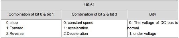 NOTE: A digital tube is corresponding to one bit above.