
1. Safety and Precautions
Safety definition:
In this manual, safety precautions are classified as follows:
 Danger: Operations which are not performed according to requirements may cause serious
equipment loss or personnel injury.
 Caution: Operations which are not performed according to requirements may cause medium hurt or light hurt or material loss.
During the installation, commissioning and maintenance of the system, please make sure to follow the
safety and precautions of this chapter. In case of a result of illegal operations, caused any harm and losses is nothing to do with the company.
1.1 Safety Precautions
1.1.1 Before Installation:
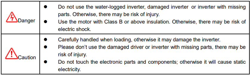
1.1.2 During Installation:
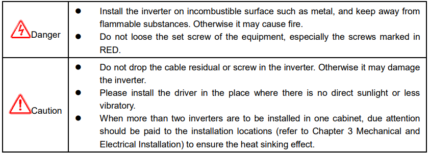
1.1.3 During Wiring:
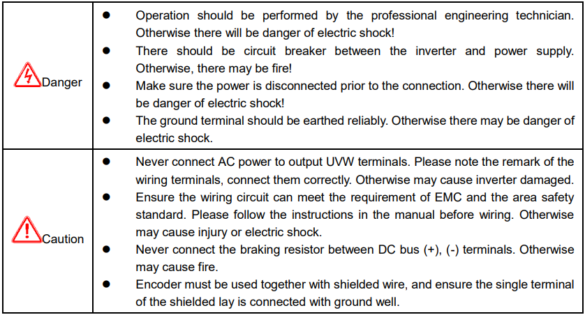
1.1.4 Before Power-on:
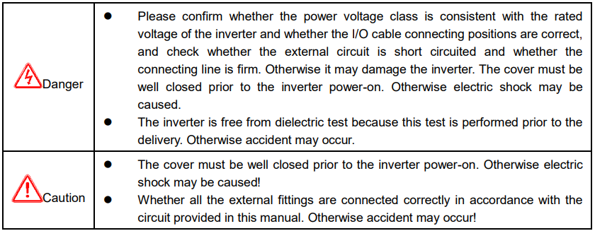
1.1.5 After Power-on:
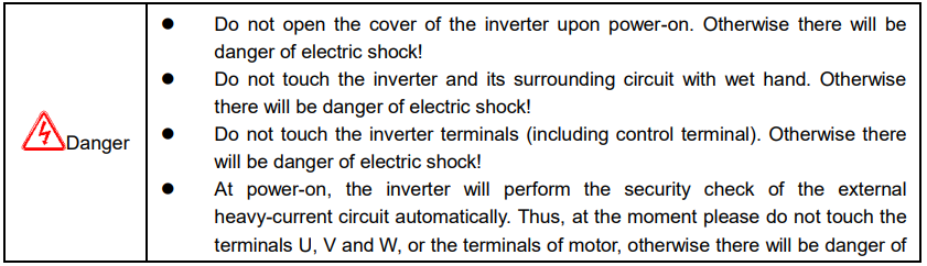

1.1.6 During Operation:
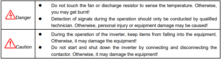
1.1.7 During Maintain:
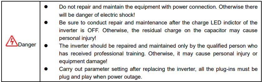
1.2 Precautions
1.2.1 Motor Insulation Inspection
When the motor is used for the first time, or when the motor is reused after being kept, or when periodical inspection is performed, it should conduct motor insulation inspection so as to avoid damaging the inverter because of the insulation failure of the motor windings. The motor wires must be disconnected from the inverter during the insulation inspection. It is recommended to use the 500V megameter, and the insulating resistance measured should be at least 5MΩ.
1.2.2 Thermal Protection of the Motor
If the ratings of the motor does not match those of the inverter, especially when the rated power of the inverter is higher than the rated power of the motor, the relevant motor protection parameters in the in the inverter should be adjusted, or thermal relay should be mounted to protect the motor.
1.2.3 Running with Frequency higher than Standard Frequency
This inverter can provide output frequency of 0Hz to 3000Hz. If the user needs to run the inverter with frequency of more than 50Hz, please take the resistant pressure of the mechanical devices into consideration.
1.2.4 Vibration of Mechanical Device
The inverter may encounter the mechanical resonance point at certain output frequencies, which can be avoided by setting the skip frequency parameters in the inverter.
1.2.5 Motor Heat and Noise
Since the output voltage of inverter is PWM wave and contains certain harmonics, the temperature rise, noise and vibration of the motor will be higher than those at power frequency.
1.2.6 Voltage-sensitive Device or Capacitor Improving Power Factor at the Output Side
Since the inverter output is PWM wave, if the capacitor for improving the power factor or voltage sensitive resistor for lightning protection is mounted at the output side, it is easy to cause instantaneous over current in the inverter, which may damage the inverter. It is recommended that such devices not be used.
1.2.7 Switching Devices like Contactors Used at the Input and Output terminal
If a contactor is installed between the power supply and the input terminal of the inverter, it is not allowed to use the contactor to control the startup/stop of the inverter. If such contactor is unavoidable, it should be used with interval of at least one hour. Frequent charge and discharge will reduce the service life of the capacitor inside the inverter. If switching devices like contactor are installed between the output end of the inverter and the motor, it should ensure that the on/off operation is conducted when the inverter has no output. Otherwise the modules in the inverter may be damaged.
1.2.8 Use under voltage rather than rated voltage
If the KE series inverter is used outside the allowable working voltage range as specified in this manual, it is easy to damage the devices in the inverter. When necessary, use the corresponding step-up or step-down instruments to change the voltage.
1.2.9 Change Three-phase Input to Two-phase Input
It is not allowed to change the KE series three-phase inverter into two-phase one. Otherwise, it may cause fault or damage to the inverter.
1.2.10 Lightning Impulse Protection
The series inverter has lightning over current protection device, and has certain self-protection capacity against the lightning. In applications where lightning occurs frequently, the user should install additional protection devices at the front-end of the inverter.
1.2.11 Altitude and Derating
In areas with altitude of more than 1,000 meters, the heat sinking effect of the inverter may turn poorer due to rare air. Therefore, it needs to derate the inverter for use. Please contact our company for technical consulting in case of such condition.
1.2.12 Certain Special Use
If the user needs to use the inverter with the methods other than the recommended wiring diagram in this manual, such as shared DC bus, please consult our company.
1.2.13 Note of Inverter Disposal
The electrolytic capacitors on the main circuit and the PCB may explode when they are burnt. Emission of toxic gas may be generated when the plastic parts are burnt. Please dispose the inverter as industrial wastes.
1.2.14 Adaptable Motor
1) The standard adaptable motor is four-pole squirrel-cage asynchronous induction motor. If such motor is not available, be sure to select adaptable motors in according to the rated current of the motor. In applications where drive permanent magnetic synchronous motor is required, please consult our company;
2) The cooling fan and the rotor shaft of the non-variable-frequency motor adopt coaxial connection. When the rotating speed is reduced, the cooling effect will be poorer. Therefore, a powerful exhaust fan should be installed, or the motor should be replaced with variable frequency motor to avoid the over heat of the motor.
3) Since the inverter has built-in standard parameters of the adaptable motors, it is necessary to perform motor parameter identification or modify the default values so as to comply with the actual values as much as possible, or it may affect the running effect and protection performance;
4) The short circuit of the cable or motor may cause alarm or explosion of the inverter. Therefore, please conduct insulation and short circuit test on the newly installed motor and cable. Such test should also be conducted during routine maintenance. Please note that the inverter and the test part should be completely disconnected during the test.