10. Extension Card
This chapter introduces the different kinds of extension cards of KE600 series inverter.
10.1 Injection Card
10.1.1 Introduction of injection card
When customers want to apply KE600 series inverter on the injection molding machine, the injection card must be used (optional). It is used to sample and process the pressure and flow signals in the injection molding machine, and the signal is current type (0~1A).
The injection card build-in two channels of processing circuit for differential current input signals. The card is connected with J8.
The model of injection card is KE600-ZS-01.
10.1.2 Specification of injection card

10.1.3 Operation instruction of injection card
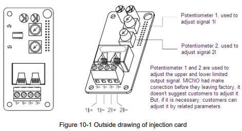
This card provides four terminals.
1I+, 1I- is the current signal input channel 1, the correspond external channel is AI1, and function code is P0-03=2, related parameters are P4-13~P4-16.
2I+, 2I- is the current signal input channel 2, the correspond external channel is AI2, and function code is P0-04=3, related parameters are P4-17~P4-20.
The combination type of these two signals is defined by P0-07. When making the wiring connection, please be very careful of the current positive and negative poles, otherwise the system cannot work properly.

10.2 PG Card
10.2.1 Introduction of PG card
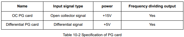
KE600 series inverter is compatible with close-loop vector control mode. Under the close-loop vector control mode, the PG card is necessary (optional).
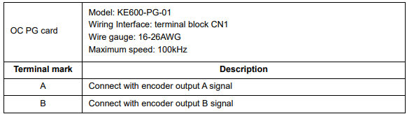
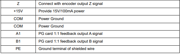
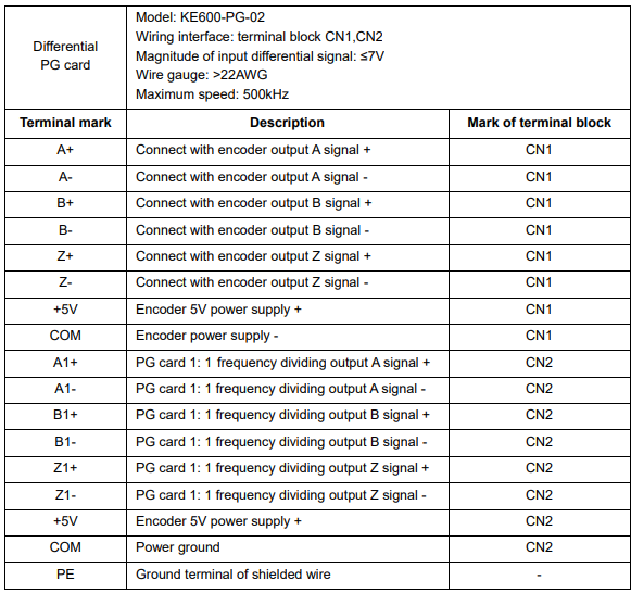
At present, KE600 is compatible with two kinds of PG cards; they connect with J6 on the control board.
Table 10.2 lists the brief technical specification of PG card.
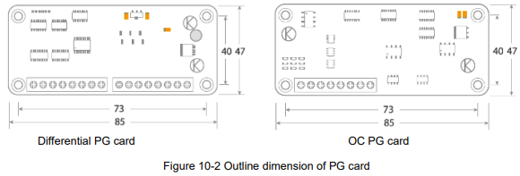
Figure 10.2 shows the outline dimension of PG card, the unit is mm.
10.2.2 Description of terminals on PG card


10.3 I/O Extension Card
10.3.1 Introduction of I/O card
I/O extension card is used to extend input and output terminals for inverter. The model No. is KE600-DG-01. It is connected with J8 on the control board.
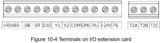
The I/O extension card provides the following terminals:
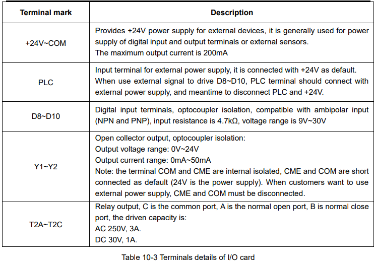
1, Digital Input terminals: 3 channels.
2, Digital Output terminals: 2 channels, open collector type output.
3, Relay output terminals: 1 channel, Normal Open and Normal Close.
4, Communication interface: 1 channel, standard RS485 interface.
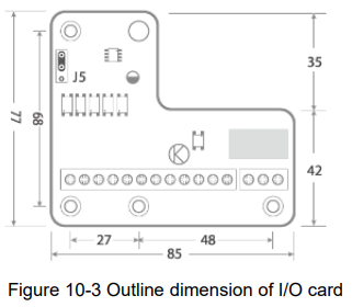
As shown in figure 10-3, jumper J5 is used to connect the terminal resistance of RS485 communication, to connect with the top two PINs, the resistance is effective.
10.3.2 Description of terminals on I/O extension card
10.4 Communication Extension Card
10.4.1 Introduction of communication card
Communication extension card is used to extend the communication terminals for inverter. It is specially used for Modbus communication function, and the card adopts electrical isolation design. The communication card’s model No. is: KE600-RS485-02 It is connected with J8 on the control board.
The communication card provides the following terminals:
Communication interface: 1 channel, standard RS485 interface.
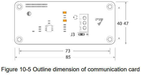
As shown in figure 10-5, jumper J3 is used to connect the terminal resistance of RS485 communication, to connect with the left two PINs, the resistance is effective.
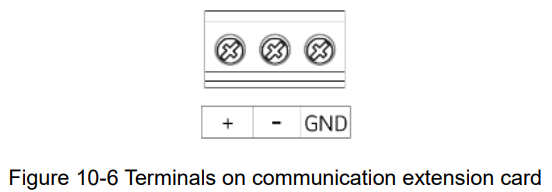
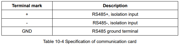
10.4.2 Description of terminals on communication extension card