
6. Parameter Description
Group P0 Basic Function

1: G model: Applicable to constant torque load.
KE600 series inverter is only suitable for G mode, for constant torque load.

0: V/F control
It is suitable for general purpose application such as pumps, fans etc. One inverter can drive multiple motors.
1: Sensorless vector control
It is widely used for the application which requires high torque at low speed, high speed accuracy, and quicker dynamic response, such as machine tool, injection molding machine, centrifugal machine and wire-drawing machine, etc.
2, Close-loop vector control
The motor must fix an encoder, the inverter has to fix an additional PG card which matches with the encoder. It is suitable for the applications which need high accurate speed control or torque control. One inverter can drive only one motor. The applications are paper making machine, hoist machine, elevator etc.
Note:
1, The autotuning of motor parameters must be accomplished properly if you use the sensorless vector control. How to autotuning of motor parameters please refer to P4 Group.
In order to achieve better control characteristic, the parameters of vector control (P2 Group) should be adjusted.
2, If close-loop vector control mode is selected, it should also set correct parameter of encoder like encoder resolution, encoder type etc.
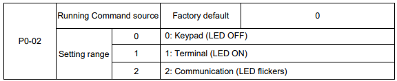
Select the input channel for control command. The inverter control commands include start, stop, forward run, reverse run, Jog and so on.
0: Keypad (“LOCAL/REMOT” LED OFF)
Both RUN and STOP/RST keys are used for running command control. If multifunction key QUICK/JOG is set as FWD/REV switching function (P7-01 is set to be 2), it will be used to change the rotating orientation. If multifunction key QUICK/JOG is set as FWD jog (P7-01 is set to be 3) or REV jog (P7-01 is set to be 4), it will be used for jog running.
1: Terminal (“LOCAL/REMOT” LED ON)
The operations, including FWD, REV, JOGF, JOGR, etc. can be controlled by multifunctional input terminals.
2: Communication (“LOCAL/REMOT” LED flickers) The operation of inverter can be controlled by host through communication.
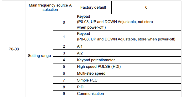
0: Keypad (not store)
The initial value is the value of P0-08. The setting frequency value of inverter can be modified through the keys “▲” and “▼” of the keyboard (or UP and DOWN of multifunctional input terminals).
“Not store” means that the setting frequency is recovered to the value of P0-08 in case of inverter poweroff.
1: Keypad (store)
The initial value is the value of P0-08.
“Store” means that the setting frequency remains the same as the value before inverter power-off.
2: Al1
3: Al2
The reference frequency is set by analog input. KE600 series inverter provides 2 analog input terminals (AI1, AI2). Both of AI1 and AI2 are 0~10V / 0~20mA input terminal.
User can select the corresponding relation between the objective frequency and the input voltage value of AI freely. KE600 series inverter provides 3 corresponding relation curves which can be set by users through P4 group function code.
4: Keypad potentiometer
The reference frequency is set by keypad potentiometer.
5: High speed PULSE (HDI)
The reference frequency is set by high speed pulse.
Pulse reference signal specification: the voltage range is 9V to 30V, and the frequency range is 0kHz to 50kHz. Pulse given can only be input from the multifunctional input terminal HDI.
6: Multi-step speed
The reference frequency is determined by P4 and PC groups. The selection of steps is determined by combination of multi-step speed terminals.
7: Simple PLC
User can set reference frequency, hold time, running direction of each step and acceleration/deceleration time between steps. For details, please refer to description of PC group.
8: PID
The reference frequency is the result of PID adjustment. For details, please refer to description of PA group.
9: Communication
The reference frequency is set through RS485. For details, please refer to Modbus protocol in Chapter 9.
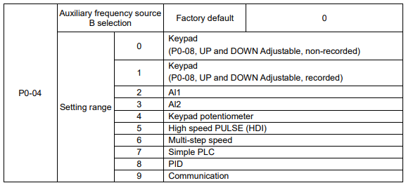
When the auxiliary frequency source is used as independent frequency reference channel (i.e. frequency source switching from A to B), it is used in the same way as the main frequency source. Please refer to P0-03.
When the auxiliary frequency source is used as combination reference, please note:
1. If the auxiliary frequency source is keypad reference, the frequency (P0-08) is invalid, and it needs to adjust the main reference frequency through the keys “▲”and “▼” of the keyboard (or UP and DOWN of multifunctional input terminals).
2. If the auxiliary frequency source is analog input reference (AI1, AI2) or pulse input reference, 100% of input corresponds to the auxiliary frequency source range (refer to P0-05 and P-06).
3. If the frequency source is pulse input reference, it is similar to the analog input reference.
Note: P0-03 and P0-04 can’t be set to be the same value. Otherwise, disorder will occur.
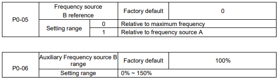
When the frequency source selection is frequency combination reference (P0-07 is set to 1 or 3), the two parameters are used to determine the adjustment range of auxiliary frequency source.
P0-05 is used to determine the relative object of that range. If it is relative to maximum frequency A, that range will change with the main frequency A.
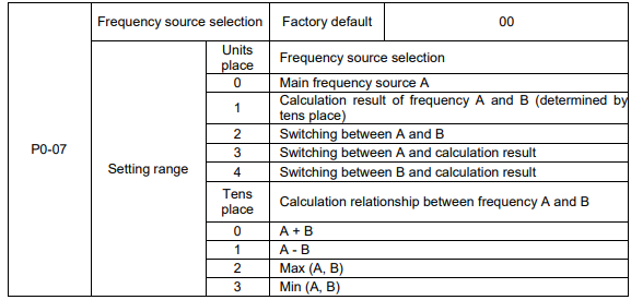
Units place: Frequency source selection
0: Main frequency source A
Reference frequency = A
1: Calculation result of frequency A and B
Reference frequency = Calculation result of frequency A and B (determined by tens place)
2: Switching between A and B
If the multifunctional input terminal HDI (P4-0X=18: frequency switching) is invalid, reference frequency = A.
If the multifunctional input terminal HDI (frequency source switching) is valid, reference frequency = B.
3: Switching between A and calculation result
If the multifunctional input terminal HDI (frequency switching) is invalid, reference frequency = A.
If the multifunctional input terminal HDI (frequency switching) is valid, reference frequency = calculation result.
4: Switching between B and calculation result
If the multifunctional input terminal HDI (frequency switching) is invalid, reference frequency = B.
If the multifunctional input terminal HDI (frequency switching) is valid, reference frequency = calculation result.
Tens place: Frequency source main/auxiliary calculation relationship
0: A + B
Reference frequency = A + B, achieving frequency combination given function.
1: A - B
Reference frequency = A - B
2: Max (A, B)
Reference frequency = Max (A, B)
3: Min (A, B)
Reference frequency = Min (A, B)
Note: When the frequency source selection is main/auxiliary calculation, the preset offset frequency can be set via P0-21, which can be added to main/auxiliary calculation result to meet different kinds of demand.

When the main frequency source is selected as “Keypad” or “Terminals UP/DN”, this function code is the initial value of frequency digital setting of the inverter.

Through modifying this function code, it can change the rotary direction of the motor without changing motor wiring. It’s equal to adjust any two lines of the motor (U, V and W) and further change the rotary direction of the motor.
Note: If the parameters are restored, the running direction will be back to its original status.

The maximum output frequency of KE600 series inverter is 3000Hz.
When P0-22 is set to 1, frequency resolution is 0.1Hz, P0-10 setting range is 50.0Hz~3000.0Hz;
When P0-22 is set to 2, frequency resolution is 0.01Hz, P0-10 setting range is 50.0Hz~300.0Hz.
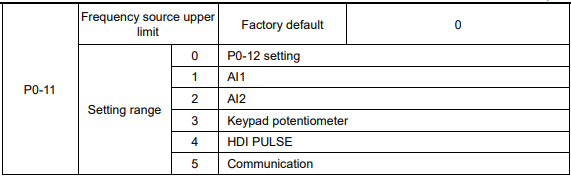
It is used to define the source of frequency upper limit. The frequency upper limit can be sourced from either digital setting (P0-12) or analog input. When the analog input is used to set the frequency upper limit, 100% of analog input setting is relative to P0-12.
Notice:
Upper frequency limit should exceed than the maximum frequency.
Output frequency should not exceed upper frequency limit.
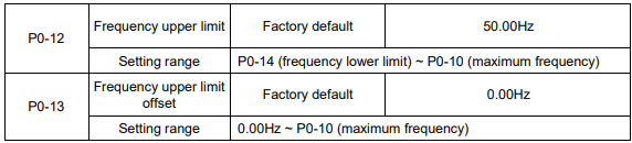
When the frequency source upper limit is analog value or HDI pulse, P0-13 is used as the setting value’s offset. The combination of this offset frequency and P0-12 is used as the final setting value of frequency upper limit.

If the reference frequency is lower than frequency lower limit, the inverter can stop, or run with lower limit frequency, or run at zero speed, which is set by P8-14.

Carrier frequency will affect the noise of motor and the EMI of inverter.
If the carrier frequency is increased, it will cause better current wave, less harmonic current and lower noise of motor.
Notice:
The factory default is optimal in most cases. Modification of this parameter is not recommended.
If the carrier frequency exceeds the factory default, the inverter must be derated because the higher carrier frequency will cause more switching loss, higher temperature rise of inverter and stronger electromagnetic interference.
If the carrier frequency is lower than the factory default, it is possible to cause less output torque of motor and more harmonic current.
The effect of modifying carrier frequency is as following:
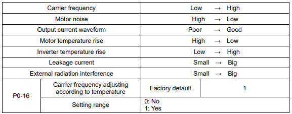
The inverter can automatically adjust the carrier frequency according to its temperature. This function can reduce the possibility of overheat alarm of the inverter.

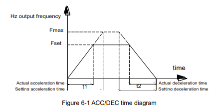
Acceleration time is the time of accelerating from 0Hz to ACC/DEC time reference frequency (P0-25).
Deceleration time is the time of decelerating from ACC/DEC time reference frequency (P0-25) to 0Hz.
Please refer to following figure.
There are totally four groups of acceleration/deceleration time which can be selected via the multifunctional digital input terminals.
Group 1: P0-17, P0-18;
Group 2: P8-03, P8-04;
Group 3: P8-05, P8-06;
Group 4: P8-07, P8-08.

KE600 series inverter offers three ACC/DEC time units, they are 1s, 0.1s, 0.01s.
Note: When modifying this function parameter, 4 group ACC/DEC time display decimal place
changes, the corresponding ACC/DEC time also changes.

This function code is only valid when frequency source is set to be main/auxiliary calculation.
When frequency source is set to be main/auxiliary calculation, P0-21 is offset frequency, which can be
combined with main/auxiliary calculation result setting as reference frequency.

This parameter is used to determine the resolution of all the function codes related to frequency.
When frequency resolution is 0.1Hz, the MAX. output frequency is 3000.0Hz. When frequency resolution is 0.01Hz, the MAX. output frequency is 300.00Hz.
Note: When modifying this parameter, the decimal place of all the parameters related to frequency
changes, the corresponding frequency value changes too.

This function is only valid when frequency source is set by keypad
0: No store means that the keypad setting frequency value would recover to the value of P0-08 (preset frequency) after the inverter stopped. The frequency modification by keys “▲”, “▼” or terminal UP, DOWN would be cleared.
1: Store means that the keypad setting frequency would recover to the last frequency when inverter stopping. The frequency modification by keys “▲”, “▼” or terminal UP, DOWN is valid.

KE600 is compatible with 2 motors driving in different time, two motors can be set different parameters (motor nameplate) separately, these two motors can perform autotuning, select different control mode and set different operation parameters individually. Parameters P1 and P2 group is special for motor1, A2 group is for motor2, customers can select motor1 or motor2 by P0-24.

ACC/DEC time is ACC/DEC time from 0Hz to the frequency set by P0-25, figure 6-1 is ACC/DEC time schematic diagram.
When P0-25 is set to 1, ACC/DEC time is related to setting frequency. The motor acceleration will change if setting frequency changes frequently.

This parameter is only valid when frequency source is set by keypad.
It is used to confirm which mode would be used to modify setting frequency when keys “▲”, “▼” or terminal UP, DOWN acts, namely, whether reference frequency increases/decreases on the basic of running frequency, or increases/decreases on the basic of setting frequency.
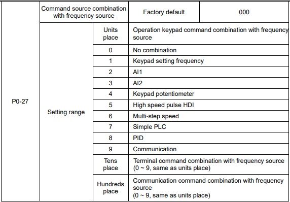
Defining the combination between three running command channels and nine frequency given channels, it’s convenient to achieve synchronous switching.
The meaning of the above frequency given channels is the same as the selection of the main frequency source A (P0-03). Please refer to P0-03.
Different running command channels can bind the same frequency given channel.
When command source binds frequency source & command source is valid, the frequency source set by P0-03 ~ P0-07 is invalid.
Group P1 Motor 1 Parameters
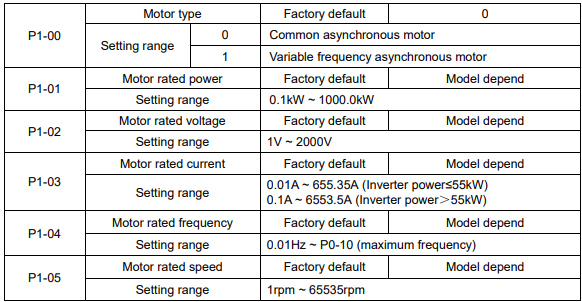
1. Please set the parameters correctly according to the motor nameplate.
2. In order to achieve superior control performance, please perform motor parameters autotuning. The accuracy of autotuning is closely related to the correct setting of the rated motor parameters.
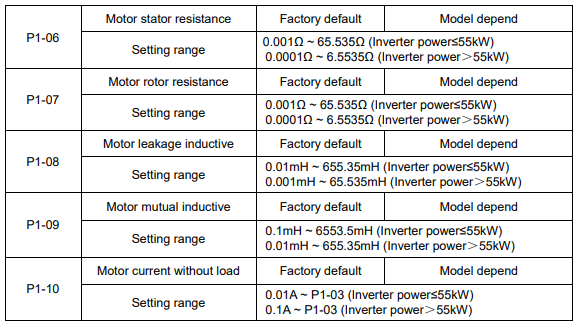
P1-06 ~ P1-10 are motor parameters, which cannot be found on the motor nameplate, and are obtained via the inverter autotuning. The static autotuning only can obtain P1-06 ~ P1-08. The rotation autotuning not only can obtain P1-06 ~ P1-10, but also can get current loop PI parameter, etc.
When P1-01 or P1-02 changed, the values of P1-06 ~ P1-10 will be changed automatically, and restore
P1-06 ~ P1-10 as standard Y series motor parameters.
If motor parameters autotuning failed in the site, please input the related parameters provided by the motor manufacturer.

0: No operation, prohibit motor parameter autotuning.
1: Motor parameter static autotuning, suitable for the applications which the asynchronous motor is not easy to disconnect with the load, and cannot make rotation autotuning.
Before static autotuning, please set the motor type and motor parameters (P1-00 ~ P1-05) correctly. The inverter can obtain P1-06 ~ P1-08 via static autotuning.
Action description: Set the function code to be 1, the keypad displays “TUNE”, then press RUN key, the inverter will make static autotuning.
2: Motor parameter rotation autotuning
To ensure the dynamic control performance of inverter, please select rotation autotuning. During the rotation autotuning, the motor must be disconnected with the load (i.e. no-load).
During rotation autotuning, the inverter will make static autotuning at first, and then accelerates to 80% motor rated frequency according to acceleration time P0-17, holding for a while, at last decelerates to stop according to deceleration time P0-18 and finish autotuning.
Before rotation autotuning, please set motor type and motor parameters P1-00 ~ P1-05, during rotation autotuning, the inverter can obtain P1-06~P1-10, vector control current loop PI parameters P2-13 ~ P2-16.
Action description: Set the function code to 2, the keypad displays “TUNE”, then press RUN key, the inverter will make rotation autotuning.
Note: Autotuning is valid only on keypad operation mode, cannot make autotuning under terminal and communication operation modes.

Set the pulse quantity while the motor run one cycle.
Under the close-loop vector control mode, the encoder resolution has to be set correctly, otherwise, the motor cannot run normally.

KE600 is only suitable for ABZ incremental encoder.

To set the phase-sequence of encoder A, B signal

To set the detection time of encoder cables disconnection, if the set time is 0.0s, the inverter will not detect whether the encoder cable is disconnected or not.
While the encoder cables disconnect, and the time of duration is more than P1-36, the inverter will give failure information of “E-20”.
Group P2 Vector Control Parameters
Group P2 is valid only for vector control. That is to say, when P0-01=0 or 1, it is valid, and when P0-01=2, it is invalid.
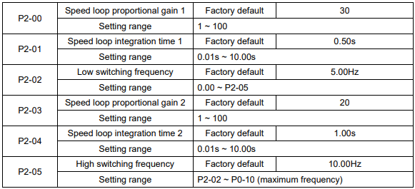
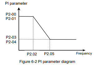
P2-00 and P2-01 are PI adjustment parameters when the running frequency is lower than low switching frequency (P2-02). P2-03 and P2-04 are PI adjustment parameters when the running frequency is higher than high switching frequency (P2-05). PI parameter of frequency channel between low switching frequency and high switching frequency is linear switching between two groups of PI parameters, as shown in the figure below:
The speed dynamic response characteristics of the vector control can be adjusted by setting the proportional coefficient and integration time of the speed regulator.
Increasing the proportional gain or reducing the integration time can accelerate the dynamic response of the speed loop. However, if the proportional gain is too large or the integration time is too short, it will cause the oscillation of the system.
Recommended adjustment method:
If factory default cannot meet the requirements, the relevant parameter values can be subject to fine tuning.
Increase the proportional gain while ensuring no oscillation to the system, and then reduce the integration time to ensure that the system has quick response characteristics and small overshoot.
Caution: Improper PI parameter setting may cause too large speed overshoot. Voltage fault may occur when the overshoot drops.

For sensorless vector control, this parameter is used to adjust the speed stabilizing precision of the motor. When the speed is too low due to heavy load of motor, this parameter needs to be enlarged, vice versa.

Under vector control mode, the output of speed loop regulator is torque current command. This parameter is used to filter the torque command. This parameter needs no adjustment generally and this filter time can be increased in case of huge speed fluctuation. In case of oscillation of motor, this parameter should be reduced properly.
The speed loop filter time is low, and the inverter output torque may fluctuate greatly, but the response is quick.

During deceleration, over excitation control can suppress bus voltage increase, avoid over voltage fault.
The bigger over excitation gain is, the better the suppression result is.
For the application which over voltage fault happens frequently during deceleration, the over excitation gain needs to be increased. But the current would be increased if the over excitation is too bigger, so you need to set the suitable over excitation gain.
For the small inertia situation, voltage doesn’t increase during motor deceleration, please set over excitation gain to 0. For the application with braking resistor, please also set over excitation gain to 0.
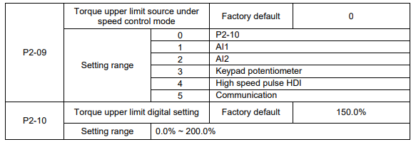
In the speed control mode, the maximum of the inverter output torque is controlled by the torque upper limit source.
P2-09 is used to select the setting source of torque upper limit. When setting via the analog value, high speed pulse HDI, communication, 100% of the relevant setting corresponds to P2-10, and 100% of P2-10 is the inverter rated torque

While the torque control linearity is higher requested, set it to be 1, and while the speed stability is higher requested, set it to be 2.
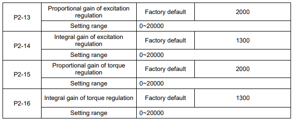
PI regulation parameters of vector control, the parameters will be got automatically after autotunning, in normal condition, they are unnecessary to be modified.
Note: if the PI gain values are set too big, it will cause the control be oscillation, while the current oscillation or torque fluctuation is bigger, the proportional gain and the Integral gain should be decreased manually.
Group P3 V/F Control Parameters
This group of function code is enabled only for V/F control (P0-01=2) and is invalid for vector control.
V/F control is applicable for the general loads such as fan and pump or the applications where one inverter drives multiple motors or the inverter power is one level lower or higher than the motor power.
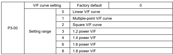
0: Linear V/F curve. It is suitable for common constant torque load.
1: Multiple-point V/F curve. It is suitable for the special loads such as dehydrator and centrifugal machine.
2: Square V/F curve. It is suitable for the centrifugal loads such as fan and pump.
3~8: VF curve between linear VF and square VF.
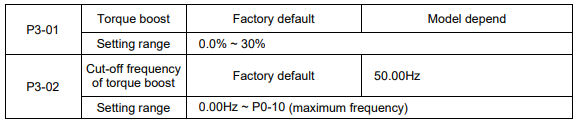
To compensate the low frequency torque characteristics of V/F control, it can boost the inverter output voltage during low frequency. If the torque boost is set to too large, the motor may be over heat, and the inverter may be over current.
Adjust this parameter according to the different loads. Increase this parameter for heavy load, reduce it for light load.
When the torque boost is set to 0.0, the inverter will adopt auto torque boost.
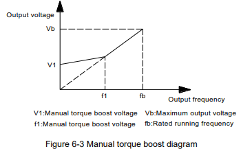
Cut-off frequency of torque boost: Under this frequency, the torque boost is valid. If it exceeds this setting frequency, the torque boost is invalid. Refer to Figure 6-3 for details.
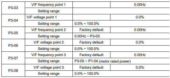
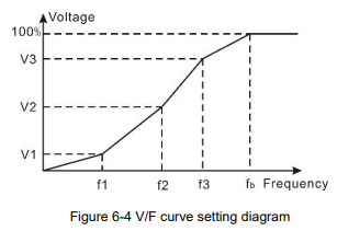
Multi-step V/F curve is defined by P3-03 to P3-08.
The curve of multi point V/F is generally set according to the load characteristics of the motor.
Caution: V1<V2<V3 and F1<F2<F3. The voltage corresponding to low frequency should not be set too high, otherwise it may cause motor overheat or inverter fault.

It is valid only for V/F control.
Setting this parameter can compensate the slip of motor speed caused by the load increases, and makes the motor speed stably when the load changes.
V/F slip compensation gain set to 100% means the slip compensation of the motor with rated load is the motor rated slip, which can be calculated according to motor rated power and motor rated speed automatically.
Slip gain adjustment can refer to the following principle: When the load is rated load, the motor speed is basically the same as the target speed. When the values are different, please adjust this gain properly.

During deceleration, over excitation control can suppress bus voltage increase, avoid over voltage fault.
The bigger over excitation gain is, the better suppression result is.
For the application which over voltage fault happens frequently during deceleration, the over excitation gain needs to be increased. But the current would be increased if the over excitation is too bigger, so you need to set the suitable over excitation gain.
For the small inertia situation, voltage doesn’t increase during motor deceleration, please set over excitation gain to 0. For the application with braking resistor, please also set over excitation gain to 0.

Set the gain as small as possible on the premise that there is effective oscillation suppression measure, which can avoid the affect causing to VF running. Set the gain to 0 when the motor has no oscillation. Only when the motor has obvious oscillation, this gain can be increased properly. The bigger the gain is, the better oscillation suppression result will be.
When using this function, please make sure the motor rated current and no load current parameters are accurate, otherwise V/F oscillation suppression result would be bad.
Group P4 Input Terminal
The standard Inverter has 7 multifunctional digital input terminals (HDI can be used as high speed pulse input terminal) and two analog input terminals.
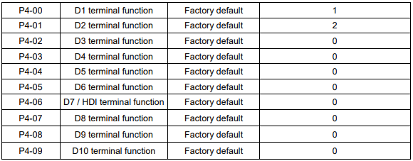
These parameters are used to set the functions of the multifunctional digital input terminals.
Note: D8, D9 and D10 are from the I/O extension card
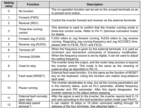
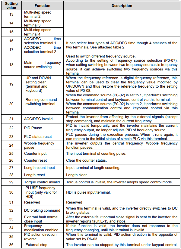
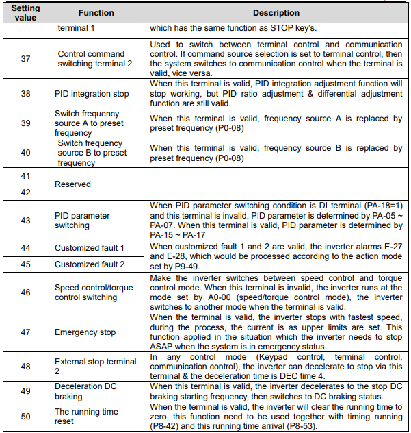
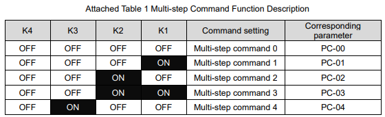
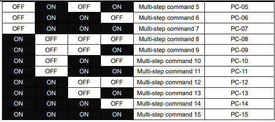
When the frequency source selection is multi-step speed, 100% of PC-00~PC-15 correspond to P0-10 (maximum frequency).
Multi-step command not only can set as multi-step speed, but also can set as PID given source, to meet the requirement of need to switch between different given values.
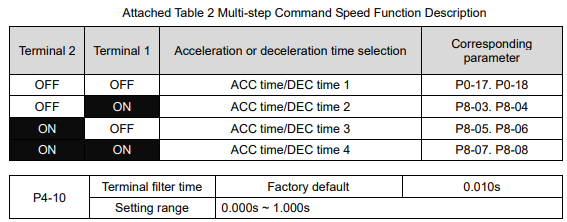
It is used to set the sensitivity of DI terminal. If the digital input terminal is vulnerable to interferences and may cause error action, it can increase this parameter value to enhance the anti-interference capability.
However, this operation will reduce the sensitivity of DI terminal.

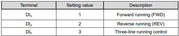
This parameter defines four different modes of controlling the operation of the inverter via the external terminals.
0: Two-line running mode 1: This is the most common mode. The forward/reverse rotation of the motor is decided by the commands of FWD and REV terminals.

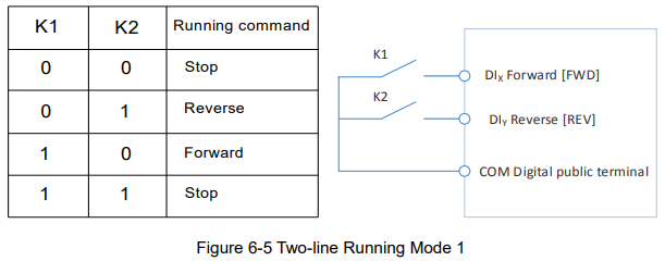
1: Two-line running mode 2: When this mode is adopted, REV is enabled terminal. The direction is determined by the status of FWD.

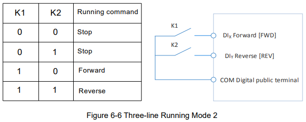
2: Three-line running mode 1: In this mode, DIn is enabled terminal, and the direction is controlled by FWD and REV respectively. However, the pulse is enabled through disconnecting the signal of DIn terminal when the inverter stops.

To make the inverter run, users must close DIn terminal firstly. It can achieve the motor forward or reverse control via pulse rising of DIx or DIy.
It can achieve the inverter stop via cutting off DIn terminal signal. DIx. DIy. DIn are DI1~DI6, HDI multifunctional input terminals, the valid input of DIx (DIy) is pulses signal, and the valid input of DIn is level signal.
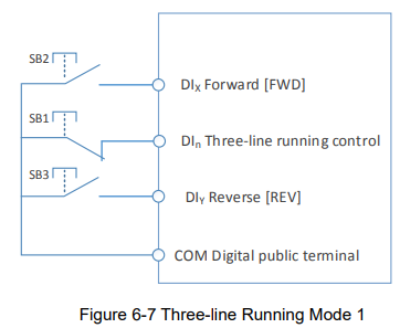
Where,
SB1: Stop button
SB2: Forward rotation button
SB3: Reverse rotation button
3: Three-line running mode 2: In this mode, DIn is enabled terminal, and the running command is given by FWD, while the direction is determined by the status of REV. Stop command is performed through disconnecting the DIn signal.
To make the inverter run, users must close DIn terminal firstly, and then the motor running signal will be generated by DIx pulse rising edge and the motor direction signal will be generated by Dy status.
It can achieve the inverter stop via cutting off DIn terminal signal. DIx. DIy. DIn are DI1~DI6, HDI multifunctional input terminals, the valid input of DIx is pulses signal, and the valid input of DIn (DIy) is level signal.
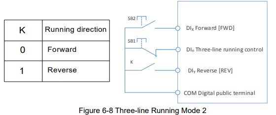
Where,
SB1: Stop button
SB2: Running button

Terminals UP/DOWN is used to adjust the change rate when setting frequency.
When P0-22 is set to 2, the range is 0.001~50.000Hz/s.
When P0-22 is set to 1, the range is 0.01~50.00Hz/s.
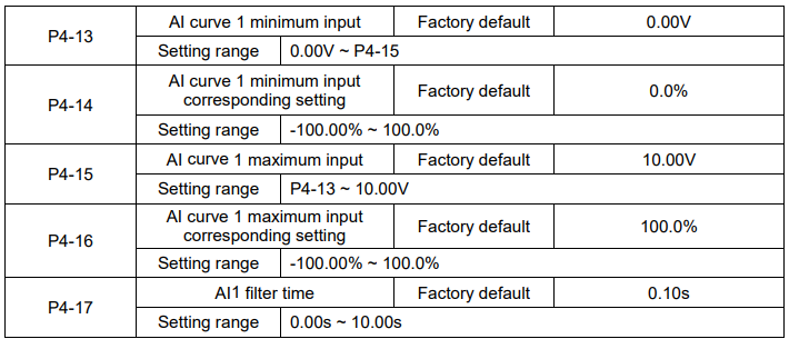
The above function codes define the relationship between the analog input voltage and analog input setting value.
When the analog input voltage is bigger than P4-15 (maximum input of AI curve 1), then calculate the analog voltage according to maximum input. When the analog input voltage is smaller than P4-13 (minimum input of AI curve 1), then calculate the analog voltage with minimum input or 0.0% according to
P4-34 (AI below minimum input setting selection).
When the analog input is current input, 1mA current equals to 0.5V voltage.
AI1 input filter time is used to set AI1 software filter time, when the site analog signal can be easily disturbed, please increase filter time to stable the detected analog signal, but the bigger the filter time is, the slower the response speed of the analog detection is . So please set this parameter according to the situation.
In difference applications, 100% of analog input corresponds to different nominal values. Refer to all the application parts for details.
Several setting examples are shown in the following figures:
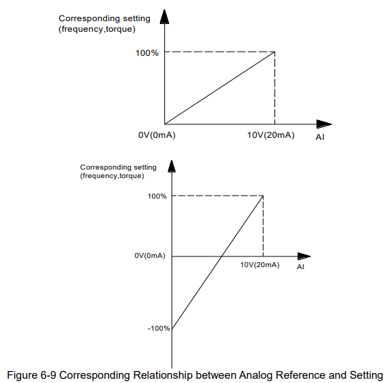
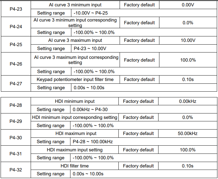
This group of function code defines the corresponding relationship when the pulse is used as frequency setting mode.
The pulse frequency input can only be input via HDI channel. The applications of this group function are similar as those of AI curve 1 function.
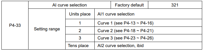
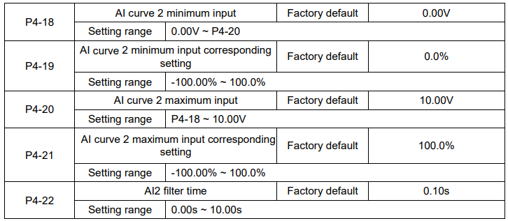
Units place and tens place of this function code are used to select analog input AI1, AI2 corresponding setting curve.
Curve 1, curve 2, curve 3 are 2 points curves, set by P4 group.
Standard inverter has 2 analog input terminals.
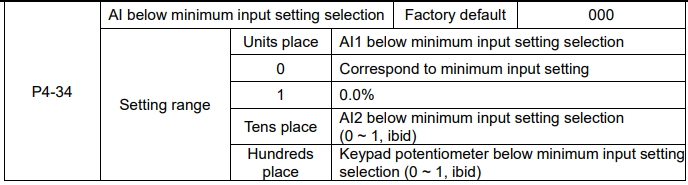
The parameter is used to set how to confirm the analog corresponding setting when the analog input voltage is lower than the setting “the minimum input”.
Units place, tens place and hundreds place of this function code correspond to the analog input AI1, AI2 and Keypad potentiometer.
If the selection is 0, when AI input is lower than “the minimum input”, the analog value corresponding setting is the curve “the minimum input corresponding setting” (P4-14, P4-19, P4-24) determined by the function code.
If the selection is 1, when AI input is lower than “the minimum input”, the analog value corresponding setting is 0.0%.
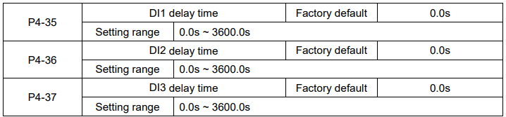
Used to set the delay time when DI terminal status changing.
Currently only DI1, DI2, DI3 have setting delay time function.
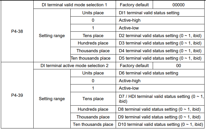
They are used to set the digital input terminal active status mode. If the selection is active-high, the relevant DI terminal connects with COM is valid, disconnect invalid. If the selection is active-high, the relevant DI terminal connects with COM is invalid, disconnect valid.
Group P5 Output Terminal
The standard Inverter has 2 multifunctional analog output terminals, 2 multifunctional relay output terminals, 1 HDO terminal (can be used as either high-speed pulse output terminal or collector open output).

HDO terminal is programmable multiplexing terminal, can be used as high-speed pulse output, with maximum frequency 100.00 kHz. Refer to P5-06 for details.
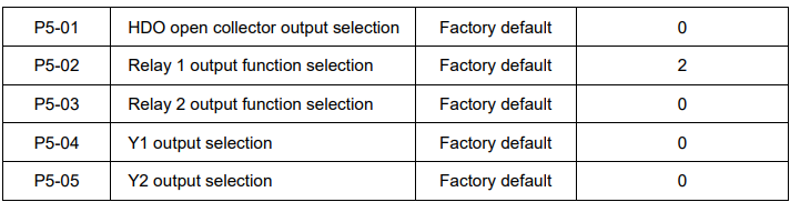
The parameters are used to select the functions of 3 digital outputs.
Multifunctional output terminal function selection is as follows:
Note:
1: Relay2, Y1 and Y2 are from the I/O extension card
2: Y1 and Y2 are open collector type output terminals.
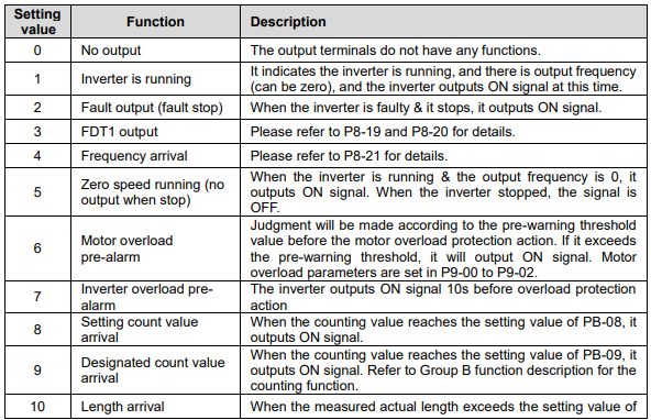
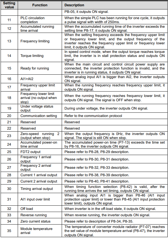
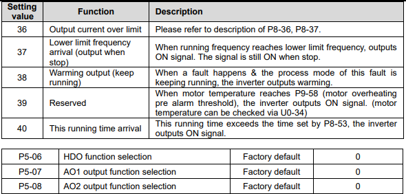
The frequency range of HDO output pulse is 0.01 kHz ~ P5-09 (HDO maximum output frequency), P5-09 can be set between 0.01 kHz ~ 100.00 kHz.
The output range of analog output (AO1 & AO2) is 0V ~ 10V or 4mA ~ 20mA.
The corresponding value range that it indicates is shown in the table below:
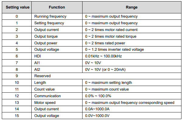

When HDO terminal is selected as pulse output, this code is used to set the maximum frequency of output pulse.
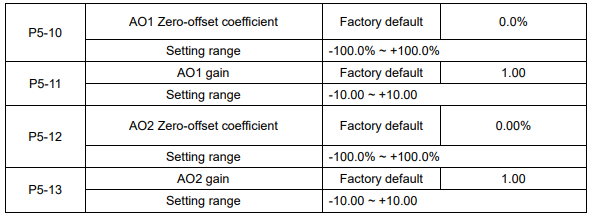
The parameters are used to correct the zero drift of the analog output and the output amplitude deviation.
They can also be used to define custom AO output curve.
If “b” represents zero offset, k represents gain, Y represents actual output, and X represents standard output, the actual output is: Y=kX+b;
Where,
100% of zero-offset coefficients of AO1 and AO2 correspond to 10V (or 20mA).
Standard output denotes 0 to maximum analog output corresponding to the output of 0 to 10V (or 4mA to 20mA) without Zero-offset and gain correction.
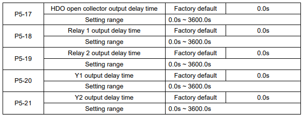
Set the delay time of output terminal HDO, relay 1 and relay 2. The delay time is time interval from the status changing to actual output changing.
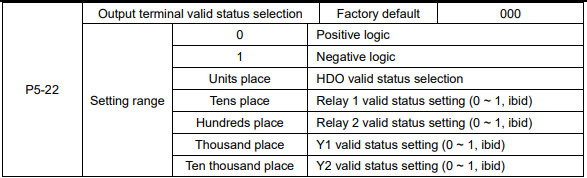
The output logic of terminal HDO, relay 1, relay 2, Y1 and Y2.
0: Positive logic, the digital output terminal connects with the relevant COM is valid, disconnect invalid.
1: Negative logic, the digital output terminal connects with the relevant COM is invalid, disconnect valid.
Group P6 Start and Stop Control

0: Direct start
If DC braking time is set to 0, the inverter will start from the start frequency.
If DC braking time is set to nonzero value, DC braking will be performed firstly, then the inverter starts from the start frequency. It is suitable for the application that the motor maybe running during starting with small inertia load.
1: Speed tracking and restart
Inverter detects the rotation speed and direction of motor, and then starts to run at the detected speed and direction. This can realize smooth start of running motor with big inertia load when instantaneous power-off.
To ensure the performance of speed tracking restart, please set motor parameters accurately. (Group P1)
2: pre-excitation start
It is only valid for asynchronous motor, used to establish magnetic field before motor running. For pre-excitation current, pre-excitation time, please refer to P6-05, P6-06 instruction.
If pre-excitation time is set to 0, the inverter will cancel the pre-excitation process, start from the starting frequency. Or the inverter will make the pre-excitation, then start, which can improve the motor dynamic response performance.

To complete the speed tracking process in the shortest time, select the suitable mode of inverter tracking motor speed:
0: To track from the frequency when stop, normally it adopts this mode.
1: To track from zero-frequency, suitable for the applications which are restarted after a long time power-off.
2: To track from maximum frequency and suitable for the general power generating loads.

It is used to select the speed tracking speed when speed tracking and restart.
The bigger this parameter is, the faster the tracking speed is. But too big value may result in unreliable tracking.

Set proper start frequency can increase the start torque.
If the reference frequency is less than start frequency, inverter will be at stand-by status, and has no output.
The start frequency could be less than the lower frequency limit.
P6-04 takes no effect during FWD/REV switching.
Example 1:
P0-03=0 Frequency source is digital reference
P0-08=2.00Hz Digital setting frequency is 2.00Hz.
P6-03=5.00Hz Start frequency is 5.00Hz.
P6-04=2.0s Start frequency holding time is 2.0s.
At this time, the inverter is at standby status, and the output frequency is 0Hz.
Example 2:
P0-03=0 Frequency source is digital setting.
P0-08=10.00Hz Digital setting frequency is10.00Hz.
P0-03=5.00Hz Start frequency is 5.00Hz.
P0-04=2.0s Start frequency holding time is 2.0s.
At this time, the inverter accelerates to 5Hz and further to the reference frequency 10Hz in 2s.
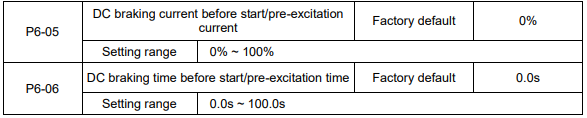
DC braking is used to make the running motor stop & restart. Pre-excitation is used to establish asynchronous motor magnetic field, then start, improve the response speed.
DC braking is only valid when start directly, the inverter performs DC braking according to P6-05 firstly, and runs after P6-06. If DC braking time is 0, the inverter starts directly. The bigger the DC braking current is, the greater the braking force is.
If the start mode is pre-excitation start, then the inverter establishes magnetic field according to the set pre-excitation current firstly, runs after the set pre-excitation time. If the pre-excitation time is 0, the inverter starts directly.
DC braking current before start/pre-excitation current refers to the percentage of the inverter rated current.

0: Linear ACC/DEC
The output frequency increases or decreases according to the straight line. KE600 series inverter has 4 kinds of ACC/DEC time, which can be set by P4-00 ~ P4-06.
1: S-curve ACC/DEC A
The output frequency increases or decreases according to S-curve. S-curve is suitable for applications which require start & stop smoothly, such as elevator and conveyor belt.
2: S curve ACC/DEC B
In the S-curve ACC/DEC B, the motor rated frequency fb is always the inflection point of S curve, showed as figure 6-11. Suitable for the applications that the high speed area above rated frequency needs fast ACC/DEC.
When setting frequency is above rated frequency, ACC/DEC time is: