
2. Software Operation
2.1. User login
1. When the stacking workstation starts, the Robot Assist software will automaticallyopen and connect the robot. After a successful connection, the stacking productioninterface will be input, and the default login user is "Operator".
When "Auto Reconnect" is always enabled, opening the Robot Assist softwarewill automatically enter the stacking production interface.
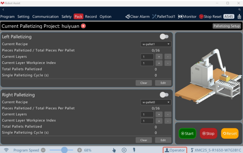
Figure Default user "Operator"
2. Click "Operator" to input the user login interface, select "Programmer" (theinitial password is 1234) or other users, input the user password, and click "Login" tologinas the selected user. The initial password for the administrator is 12345
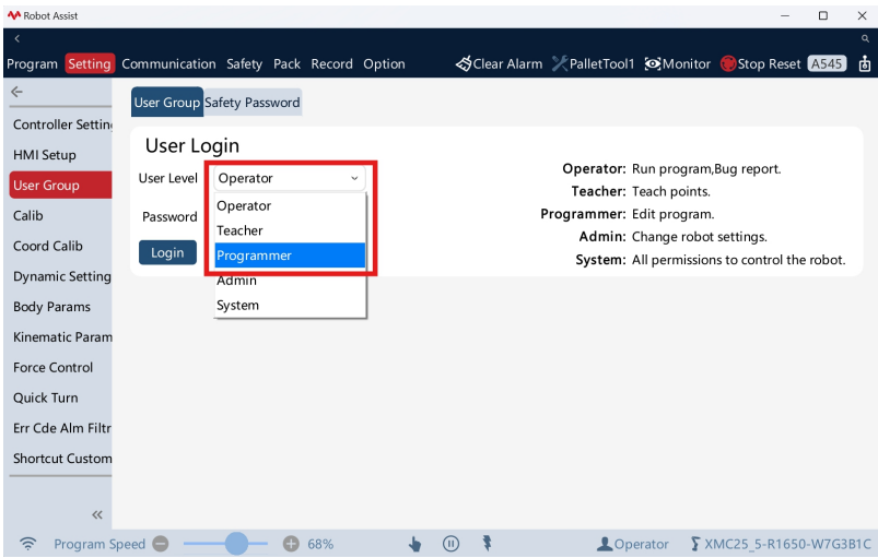
Figure Select user level
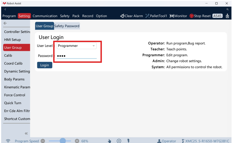
Figure Input user password
2.2. Jog adjustment
1. In manual mode, click "Enable" on the bottom status bar to power on the robot. Thepower-on status will be displayed. Click the "Control Panel" on the upper right cornerto open the control panel. Click "Jog Speed Percentage" and set the jog speedtolessthan 20%
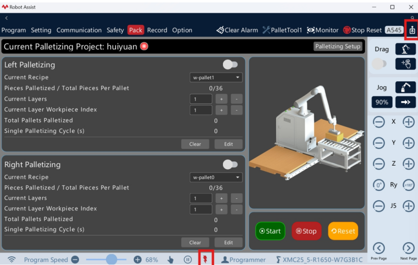
Figure Enable the robot
2. Click "Next Page" on the control panel to switch to the quick adjustment panel. Long press "Drag Pose" to quickly adjust the robot's orientation to the drag pose.
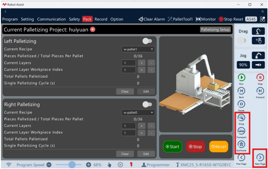
Figure Quick adjustment
3. Click "Next Page" on the control panel to switch to the jog adjustment panel. Click"Jog Frame" and select "Parallel Base Frame". Use the "+" and "-" to jogthetool position and level the attitude. Click "Control Panel" to close the control panel. Click"Enable" again to power off the robot, and the power off status will be displayed.
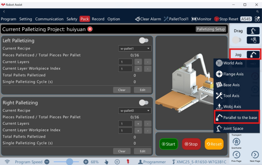
Figure Robot jogging
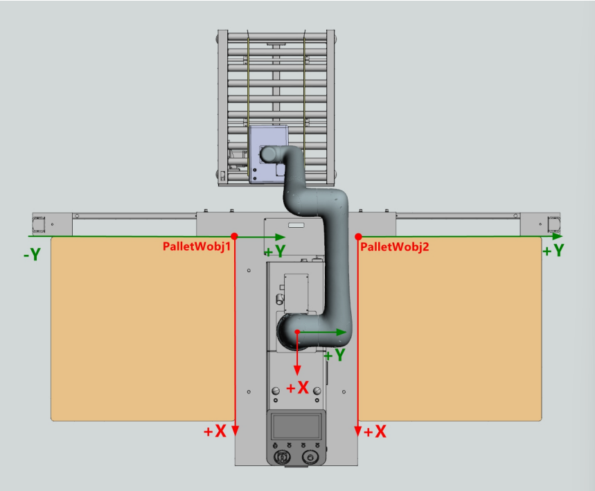
Figure Jogging direction in the base frame
2.3. Production interface
1. Click "Process Package" - "Stacking Workstation" in the top menu bar toenter thestacking production interface.
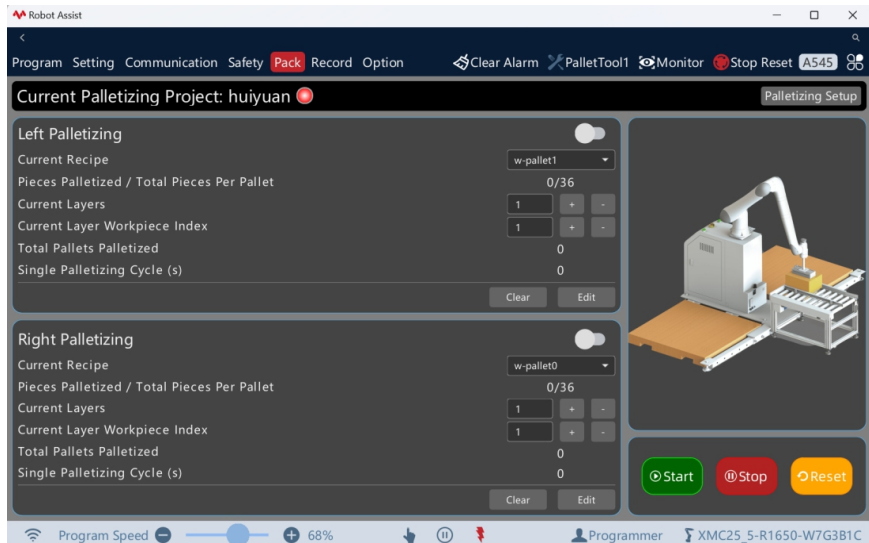
Figure Stacking production interface
Current stacking scheme: Displays the name of the currently loadedstackingscheme.
Stacking operation status light: Displays the current operation status of thestacking scheme. Stacking Workstation User Manual 9
Green: The stacking scheme is in operation.
Red: The stacking scheme has not been executed.
Left/Right stacking enable switch: The left/right pallet can be enabled/disabledasneeded. The workstation will only stack the pallets that have been enabled.
Current formula for left/right side stacking: Displays the formula currentlyusedfor stacking on the left/right side. Other formulas can be switched. Aftermodification, the stacking task will be initialized.
Number of completed products on a single pallet/total number: Displaysthenumber of products that have been placed on a single pallet on the current side/the total number of products.
Current stacking layer number: Displays the layer number being stackedonthecurrent side. When the workstation is down, the number of layers canbemodified.
Current layer work object number to be stacked: Displays the workobject number currently being placed on the current layer of the current side. Whentheworkstation is down, the work object serial number can be modified.
Total pallets stacked: Displays the total number of pallets that have beenplacedand coded on the current side.
Single stacking takt: Displays the time required for the current side to completeasingle cycle from loading materials from the conveyor line to placing them.
Reset: Reset all current production capacity data and cumulative counts.
Modify: Save and write the current stack layer number and the serial number ofthe work object to be stacked on the current layer that are currently input.
2.4. Frame setting
1. Click "Stacking Settings" - " Frame Settings" to enter the frame setting interface, which includes tool settings, pallet settings, incoming material settings, and pathpoint position compensation.
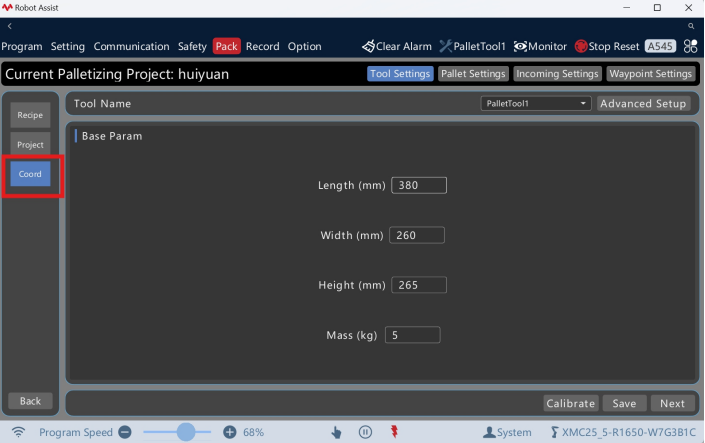
Figure Frame setting interface
2.4.1. Tool setting
The stacking tool refers to the robot end-effector, including grippers, vacuumor spongesuction cups, etc. The stacking tool frame is used to represent the actual poseof therobot end-effector.
The stacking workstation has completed the calibration of the tool frame whenit leavesthe factory. This parameter is only applicable to the suction cups shippedwiththeworkstation. When the matching suction cups are changed, the tool parameters needtobe modified according to the actual suction cup type used, and the pallet originandconveyor line origin positions need to be re-taught. Otherwise, there is no needtoset them. The formula data will not be affected. The single suction cup & concentric tool frame corresponds to the tool framePalletTool1.
For single suction cup & concentric tool frame, select PalletTool1 andinput thelength, width, and height of the suction cup. The height is the distance fromthesuction cup's adsorption surface to the flange plane.
For single suction cup & eccentric tool frame, select the tool PalletTool1andcomplete the eccentric tool frame calibration by "Calibration".
For double suction cup & concentric tool frame, select the tool PalletTool1, andinput the actual total length, total width, and height parameters of the doublesuction cups. The height is the distance from the suction cup's adsorptionsurfaceto the flange plane.


1. Click "Stacking Settings" - "Frame Settings" - "Tool Settings" to input thebasicparameter setting interface of the tool. Select tool PalletTool1, and input theactual length, width and height parameters of the suction cup. The height is the distancefromthe suction cup's adsorption surface to the flange plane.
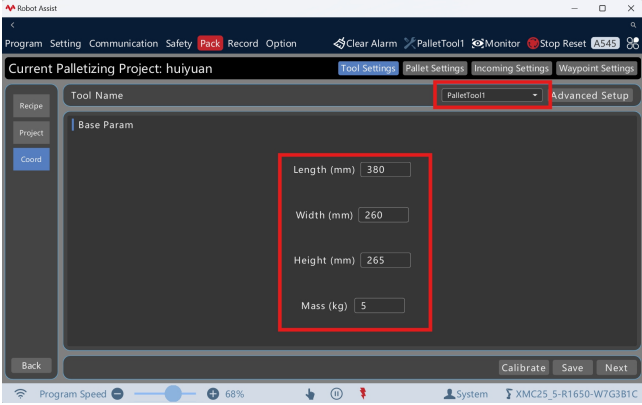
Figure Modify basic tool parameters
2. When the product is large in size and has an uneven mass distribution, click"Advanced Settings" to display advanced parameters. Input the actual TCPpositionofthe tool, TCP orientation, center of gravity of the load, and load inertia parameters. Thecollision detection sensitivity is related to the input parameters.
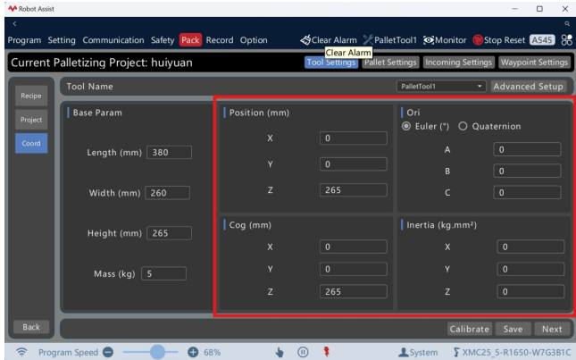
Figure Modify advanced tool parameters
3. Click "Save" to complete the modification. A confirmation box for update will popup. Click "Confirm" to update the formula data of all the created ones usingthetool PalletTool1. Click "Next" to save the modifications and enter the pallet setting
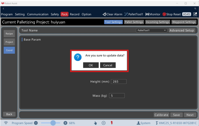
Figure Save tool settings
4. When offsetting the tool, select the tool PalletTool1, click "Calibration" to enter the tool frame calibration interface, enable the drag switch to activate the dragfunction, drag the robot's end suction cup to the origin position of the conveyor line/pallet, alignthe long side of the end suction cup with the long side of the conveyor line/pallet, andalign the wide side of the end suction cup with the wide side of the conveyor line/pallet, then click "Get Point Position" to teach the "Reference Point" position. The point position of "Move to" can be manually modified
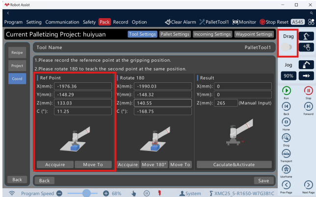
Figure Reference teach point
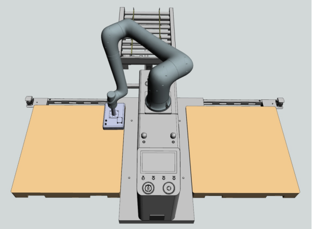
Figure Reference teach point
5. Drag the suction cup at the end of the robot to rotate the flange 180°; Alternatively, after moving the robot to a safe height, click "Rotate 180°" to rotate the flange clockwise 180°, aligning the long edge of the end suction cup with the long edgeof the conveyor line/pallet, and aligning the wide edge of the end suction cup with the wide edge of the conveyor line/pallet. Click "Get Point" to teach the "Rotate 180°" position. The point position of "Move to" can be manually modified
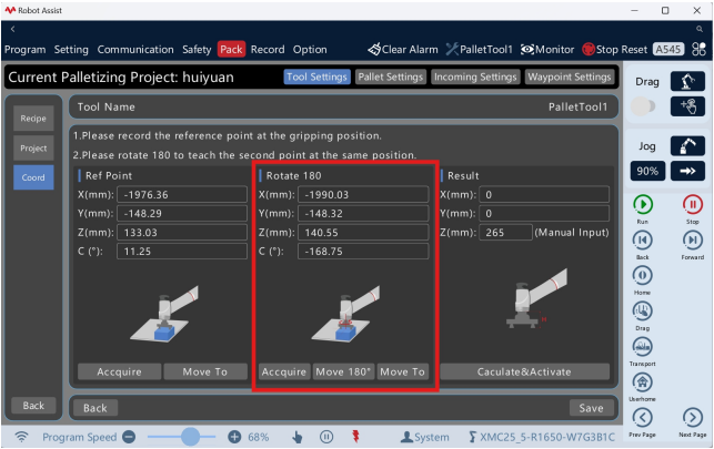
Figure Teach the rotate 180° point
6. Click "Calculate and Activate" to complete the automatic calculation of the tool TCP. Input the tool height, which is the distance from the end of the tool to the flange plane. Click "Save" to complete the calibration of the tool frame.
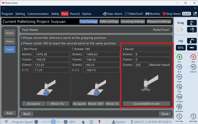
Figure Automatic calculation of tool parameters
2.4.2. Pallet setting
The pallet frame calibration of the stacking workstation is completed at the factory. This parameter is only applicable to the pallet positioning systemof ROKAE workstations. When the end tool of the robot, installation direction or pallet position is changed, the origin of the pallet frame needs to be taught according to the actual situation. Otherwise, no setting is required. The formula data will not be affected.
The frame of the left pallet corresponds to the work object frame PalletWobj1, and the frame of the right pallet corresponds to the work object frame PalletWobj2. The definition of the left and right side pallet frames for the installation direction of the robot (positive X-direction) is as follows (the origin of the frame is on the ground, and the Z-axis points upward).
Robot direction: The direction of the positive direction of robot X, the control panel side is the rear side, and the conveyor line side is the front side.
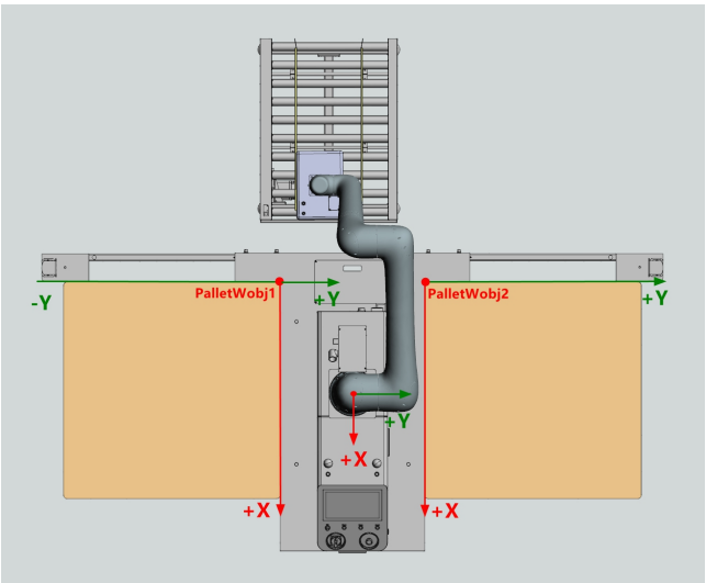
Figure Left and right pallet frames
1. Click "Stacking Settings" - "Frame Settings" - "Pallet Settings" to enter the pallet frame setting interface. The robot installation direction (positive X-direction) defaults to "Backward". Enable the drag switch to enable the drag function. Drag the robot's end suction cup to the original point position of the left/right pallet, aligning the long edge of the end suction cup with the long edge of the left/right pallet, aligning the wide edge of the end suction cup with the wide edge of the left/right pallet, and sticking the suction surface to the ground. Click "Get Point Position" to teach the "Left/Right Pallet Origin" position. The point position of "Move to" can be manually modified.
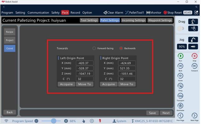
Figure Teach the left/right pallet origin
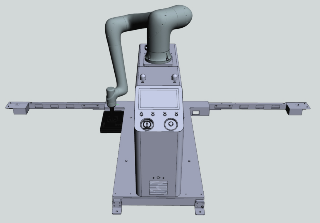
Figure Teach the left pallet origin
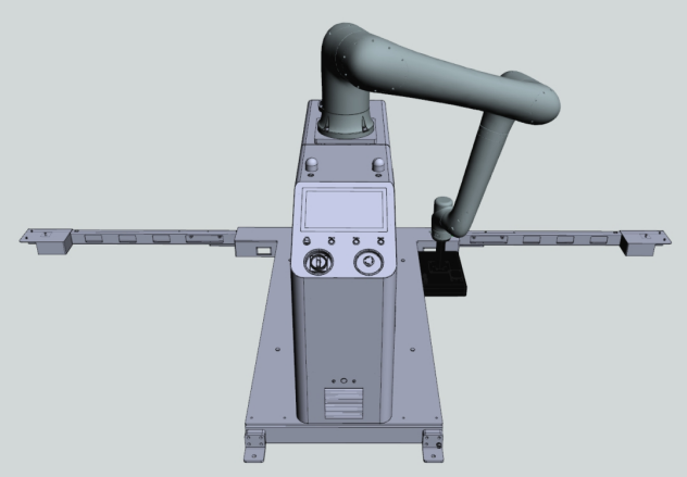
Figure Teach the right pallet origin
2. Click "Save" to complete the modification. A confirmation box for update will pop up. Click "Confirm" to update the formula data of all the created ones that use the pallet frames PalletWobj1 and PalletWobj2. Click "Next" to save the modification sand enter the incoming material setting interface.
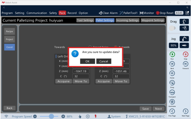
Figure Save pallet settings
2.4.3. Incoming material settings
The origin of the conveyor line needs to be taught based on the actual situation. One-time-drag teaching can complete the first on-site deployment.
1. Click "Stacking Settings" - "Frame Settings" - "Incoming Material Settings" to ente rthe incoming material setting interface. According to the actual layout of the stacking workstation and the conveyor line, set the incoming material direction of the conveyor line, the incoming material direction of the product, and the origin position of the conveyor line. When the position of the conveyor line remains unchanged and only the direction of incoming products or the types of products are altered, re-teaching is not required.
The direction of incoming materials on the conveyor line: The conveyor line feeds materials from the front side/left side/right side of the workstation.
The direction of product incoming materials: The products are fed in from the conveyor line either horizontally or vertically.
The origin position of the conveyor line: After the product is in place, its positionon the conveyor line is in the lower left corner/lower right corner
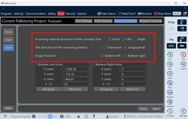
Figure Set the incoming material method
2. Enable the drag switch to enable the drag function. Drag the end suction cup of the robot to the origin position of the conveyor line or the surface of the product on the conveyor line. Regardless of whether the incoming material is placed horizontally or vertically, align the long side of the end suction cup with the long side of the conveyor line/product and the short side of the end suction cup with the short side of the conveyor line/product. Then click "Get Point Position" to teach the "Conveyor Line Origin" position. The point position of "Move to" can be manually modified. When teaching the surface of the conveyor line product, manually subtracting the box height can complete the origin positioning of the conveyor line, and the grasping point position will be automatically calculated and adjusted according to the formula used.
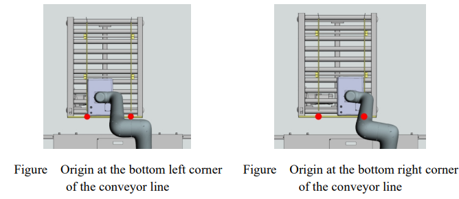
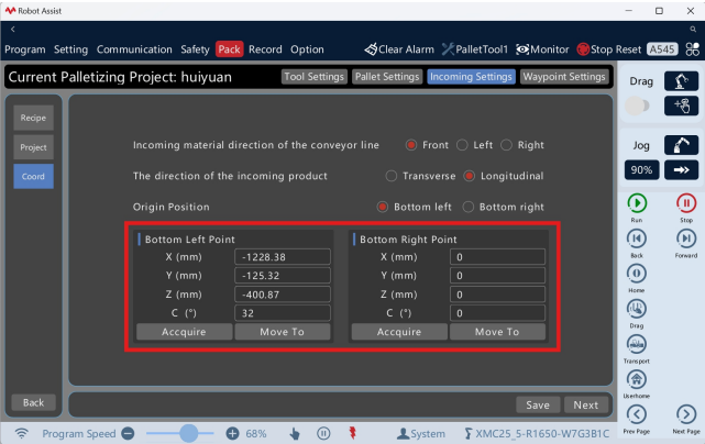
Figure Teach the conveyor line origin position
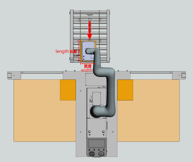
Figure Conveyor line front side incoming material, product longitudinal, origin lowe rleft corner
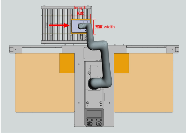
Figure Conveyor line left side incoming material, product longitudinal, origin lower left corner
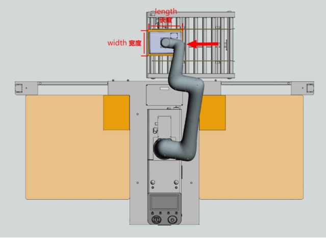
Figure Conveyor line right side incoming material, product longitudinal, origin lower left corner
3. Click "Save" to complete the modification. A confirmation box for update will pop up. Click "Confirm" to update the position of the conveyor line's grasping point. Click "Next" to save the modifications and enter the path point setting interface
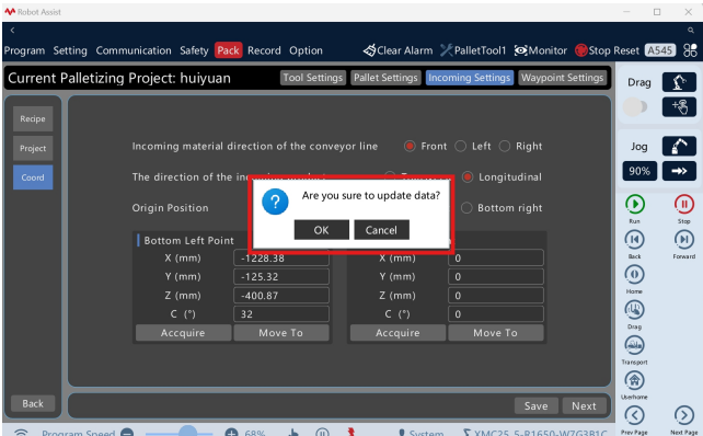
Figure Save incoming material settings
2.4.4. Path point setting
The stacking workstation has completed the path point position compensation setting up on leaving the factory. This parameter is only applicable to the workstationsystemof ROKAE.
Conveyor line material loading path point
Material loading standby point (A), material loading exit point (B): The initial position is the preset height plus the compensation value. Front-back, left-right, and height compensations can be input. Taking the control panel screen side as the reference perspective, if the offset is towards the front orleft side, the input value is positive; if the offset is towards the rear or right side, the input value is negative.
Delay time parameter
Delay time at the material loading point: The value of the delay in liftingthebox when the tool comes into contact with it after reaching the material loading point.
Delay time at the material unloading point: The value of the delay in lifting the box when the tool releases it after reaching the material unloadingpoint.
Left/right pallet material loading path
Material loading entry point (C): The initial position is outside the pallet, at the height of the material loading exit point plus the compensation value. Based on the initial position, front-back, left right, and height compensations can be input. The height of the entry point increases as the number of layers increases. Taking the control panel screen side as the reference perspective, if the offset is towards the front or left side, the input value is positive; if the offset is towards the rear or right side, the input value is negative.
Material unloading preparation point (D): The initial position is 1product height higher of the material unloading point+compensation value, and the height compensation can be input based on the initial position
Material unloading approach point (E), material unloading retract point (F): The initial position is the material unloading point+compensation value, and the height compensation can be input based on the initial position.
Material unloading exit point (G): The initial position is the material unloading point+compensation value, and the height compensation can be input based on the initial position.
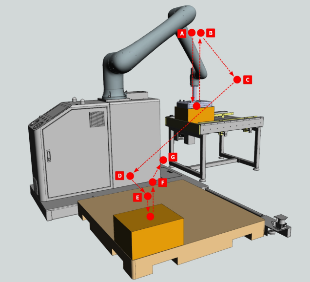
Figure Material loading/unloading path points
1. Click "Stacking Settings" - " Frame Settings" - "Path Point Settings" to enter the path point setting interface. When there is an error in placing the product at the designated position, the required position compensation can be modified
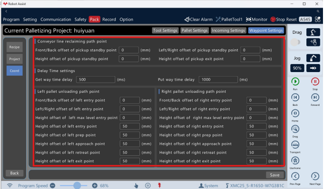
Figure Modify the position compensation of path points
2. Click "Save" to complete the modification. A confirmation box for update will pop up. Click "Confirm" to update the positions of all path points.
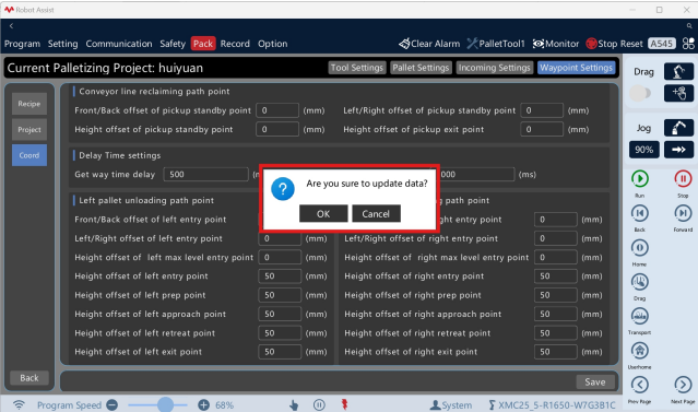
Figure Save path points settings
2.5. Formula management
The stacking formula refers to the way the product is stacked onto the pallet, including the product, the pallet, the stack pattern parameters, and the location of all stacking waypoints on the pallet.
1. Click "Stacking Settings" - "Formula Management" to enter the formula management interface. It displays the product, pallet, and stack pattern parameter sof the existing stacking formulas. You can create, edit, delete, export, and import stacking formulas. Click "Formula Name" to display a list of existing formulas.
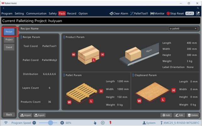
Figure Formula management interface
1. Click "New" to enter the interface for adding a new stacking formula. The formula settings include product & pallet settings, plane pattern settings, layered pattern settings, and path point adjustment settings. The current step is highlighted in the upper right corner label. Click "Next" to save the modifications and proceed to the next stepinterface. To modify previous steps, click the tabs to quickly switch to the corresponding interface.
Product & pallet settings: Set the dimensions and weights of products, pallets, and dividers.
Plane pattern settings: Set single-layer stack patterns, including arrangement styles, stacking sequences, and material placement direction offsets.
Layered pattern settings: Set the number of layers and the stack patterns of different layers.
Path point adjustment settings: Used for stack pattern accessibility checks and stacking path point adjustments.
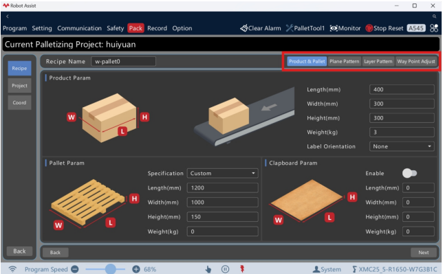
Figure Formula setting interface
2.5.1.1. Product & pallet settings
1. Click "Products & Pallets" to enter the products & pallets setting interface. Input the formula name, and input the product's length, width, height and weight. Click"Label Direction" to display the drop-down list and select the product label position.
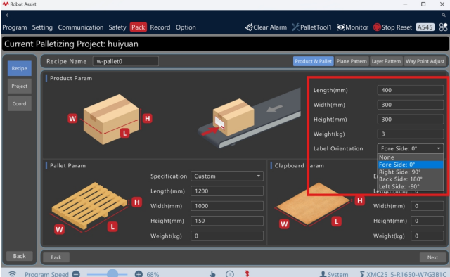
Figure Input product parameters
2. Click "Pallet Specifications" to display the drop-down list, where you can select standard pallet sizes from different regions or custom pallet dimensions. Input the actual length, width, height, and weight of the pallet. The predefined standard pallet sizes include the following specifications:
Custom
1100 mm*1100 mm
1165 mm*1165 mm
1219 mm*1016 mm
1067 mm*1067 mm
1200 mm*800 mm
1200 mm*1000 mm
800 mm*600 mm
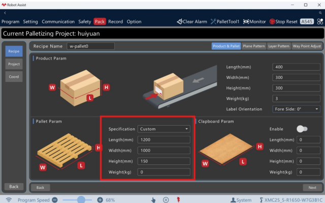
Figure Input pallet parameters
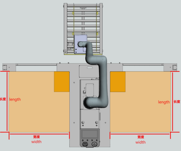
Figure Left and right side pallet direction
3. Click "Next" to save the modifications and enter the plane pattern setting interface.
2.5.1.2. Set plane pattern
1. Click "Plane Pattern" to enter the plane pattern setting interface. According to the actual situation, select "Pallet Position" and choose stack pattern style A.
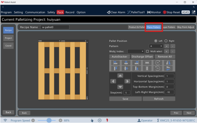
Figure Plane pattern setting interface
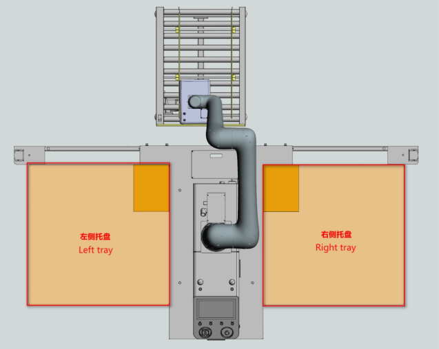
Figure Left and right side pallet position
2. Click "Plane Pattern" — "+"to add a new stack pattern style, and click"PlanePattern" — "-" to delete a stack pattern style.
3. When selecting automatic stack pattern generation, click "Automatic StackPattern"to enter the automatic stack pattern interface. The process package automaticallygenerates array, crisscross, and circular stack patterns. Input the pallet marginandproduct spacing, click "Generate Stack Pattern Again" to update the stackpattern, select the desired stack pattern, and click "Confirm" to save the stack patterntothecurrent stack pattern style.
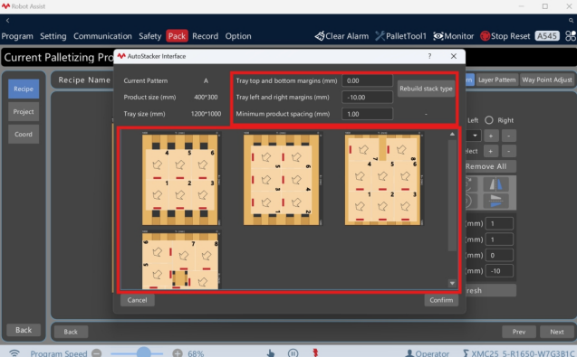
Figure Automatic generation of stack patterns
4. When selecting a custom stack pattern, input the pallet edge distance and product spacing, click the work object number "+" to add the product to the flat graphic editor, drag and drop the product to the desired stack pattern, click "Multiple selection"or single selection, click align arrangement, click "Material unloading direction offset" to pop up the unloading direction setting dialog box. You can set the direction and distance of the unloading preparation point (D) offset relative to the approach point (E) directly above the unloading point, and click "Confirm" to save.
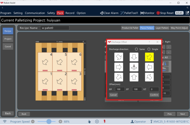
Figure Set the direction of material unloading
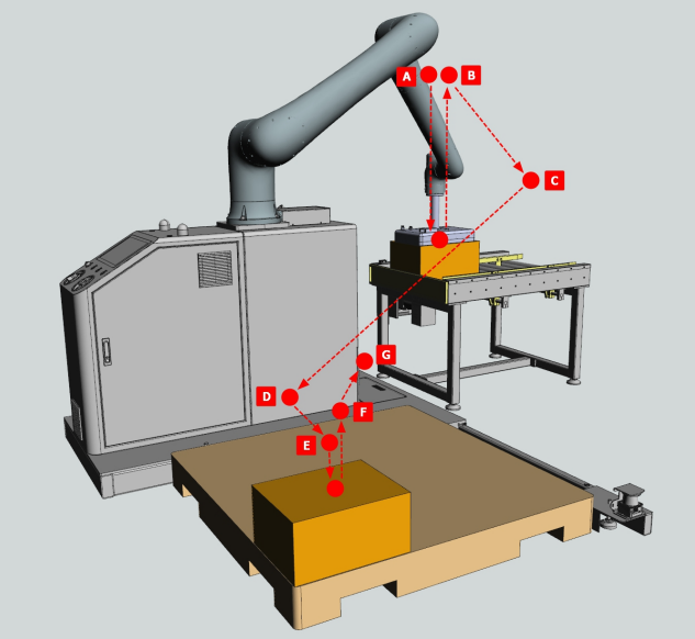
Figure Unloading direction D relative to E
5. Click "Next" to save the modifications and enter the layered pattern setting interface
2.5.1.3. Set layered pattern
1. Click "Layered Pattern" to enter the plane pattern setting interface. According to the configured stack pattern, set all layers on the current pallet and the corresponding stack pattern.
Plane pattern: Click the "Plane Pattern" drop-down box and select and preview configured stack patterns on the left.
Set to all layers: Select the desired stack pattern and click "Set to All Layers" to quickly apply the selected stack pattern to all layers.
Set to odd layers: Select the desired stack pattern and click "Set to OddLayers" to quickly apply the selected stack pattern to all odd layers.
Set to even layers: Select the desired stack pattern and click "Set to EvenLayers" to quickly apply the selected stack pattern to all even layers.
Pattern: Set the stack pattern of each layer and double-click to switch to other patterns.
Height compensation: Set the height compensation for each layer. When the height compensation is set, work object points and path points of the layer will be offset according to the compensation value as a whole.
New: Select the desired stack pattern and click "New" to add the highest layerand pattern.
Delete: Click "Delete" to delete the top layer
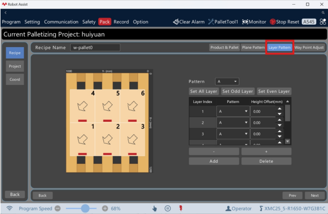
2.5.1.4. Adjust path point
1. Click "Path Point Adjustment" to enter the path point adjustment setting interface. The process package automatically calculates the positions of all the stackingpathpointsstacking path points on the current pallet. When returning to the previous step or an intermediatesteptointermediate step to modify the parameters, you need to click "Next" in sequence to completethemodification.complete the modification.
Regenerate path points: When the product size or stack pattern changes, click"click "Regenerate Path Points" to regenerate the initial point position.
Select path points: Select the drop-down list of point layer and work object serial
number, and choose the required stacking path to be modified.
Lifting column: Enable when there is a lifting column, otherwise disable. Whenenabled,When enabled, the accessibility check will override the lifting height of the liftingcolumn.
Lifting height: The initial maximum stacking height is 1.6 m; input the requiredliftingrequired lifting height.

Figure Path point adjustment interface
2. Click "Accessibility Check" to verify the accessibility of all stacking path points and trajectories. A pop-up window will prompt that the check has passed. Click "Next" to complete the formula settings.
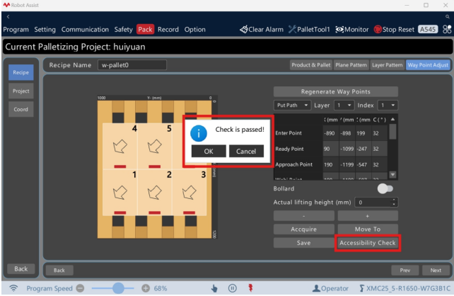
Figure Accessibility check
3. Select the layer number and work object number in the path point list, select thepoint position, and click "Move to" to test run the stacking path, and confirmthat there is no interference with the environment. Select the desired point position, dragit to the appropriate position, click "Get Point Position" to teach the current point, and click "Save". To fine-tune the point position, select the required X/Y/Z/C position and click Increase/Decrease to adjust.
2.5.2. Copy formula
1. Click "New" to enter the new stacking formula interface, input the formula name, select the formula to be copied, check "Copy", and click "Next" to complete the configuration and replication.
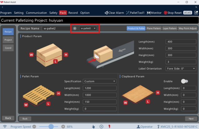
Figure Copy a stacking formula
2.5.3. Edit formula
1. Click "Formula Name" to display the formula list, select the required stacking formula, and click "Edit" to enter the interface for editing the stacking formula. Modify the formula name and configuration.
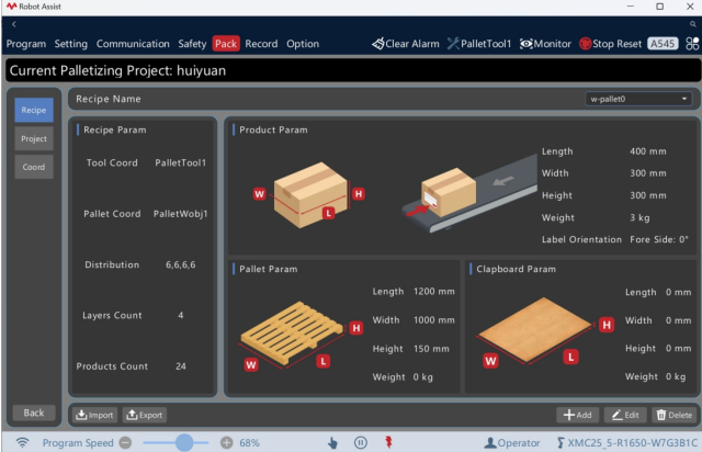
Figure Edit a stacking formula
2.5.4. Delete formula
1. Click "Formula Name" to display the formula list. Select the required stacking formula and click "Delete". A confirmation dialog box will pop up. Click "OK" to complete the deletion
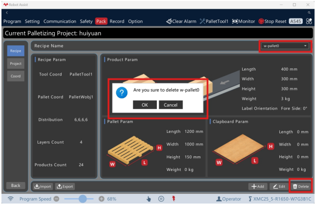
Figure Delete a stacking formula
2.5.5. Export formula
1. Click "Export" to pop up the import and export dialog box. Click "Open" to select the local directory you need to export to. Select the formula name you need to export, and click "OK" to complete the export of the formula file (.xml).
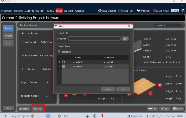
Figure Export a stacking formula
2.5.6. Import formula
1. Click "Import" to pop up the import and export dialog box. Click "Open" to select the local formula file (.xml) you need to import. When importing, choose "Auto Rename" or "Auto Replace", and click "OK" to complete the import of the formula file.
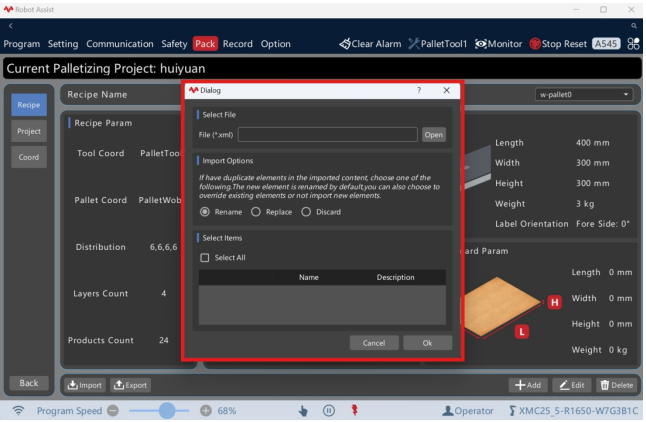
Figure Import a stacking formula
2.6. Scheme management
The stacking scheme refers to the hardware scheme for stacking, including the layout of the scheme, the type of stacking, and the hardware configuration. The process package is equipped with multiple standard stacking schemes and supports users to customize their own stacking hardware schemes. When there are different layout schemes, stacking types, and hardware configurations for a single robot in the stacking system, one-click switching can be achieved.
1. Click "Stacking Settings" - "Scheme Management" to enter the scheme management interface, which displays existing stacking schemes and parameters. You can create, edit, delete, load, export, and import stacking schemes.
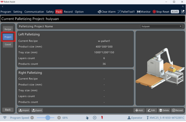
Figure Scheme management interface
1. Click "New" to enter the new stacking scheme interface, input the scheme name, and configure the scheme layout, stacking type, and hardware configuration as required.
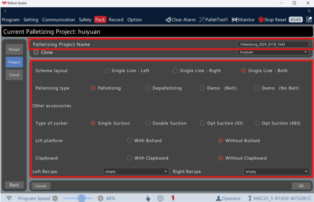
Figure Add a new stacking scheme
2. To copy the stacking scheme, check "Copy" and select the name of the scheme you want to copy.
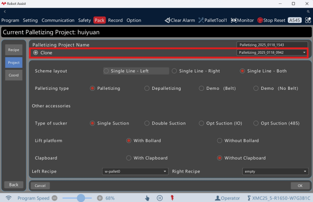 Figure Copy a stacking scheme
3. Click "Confirm", and a dialog box will pop up asking for confirmationof the addition. Click "OK" to complete the addition and load it into the newscheme, then return to the scheme management interface.
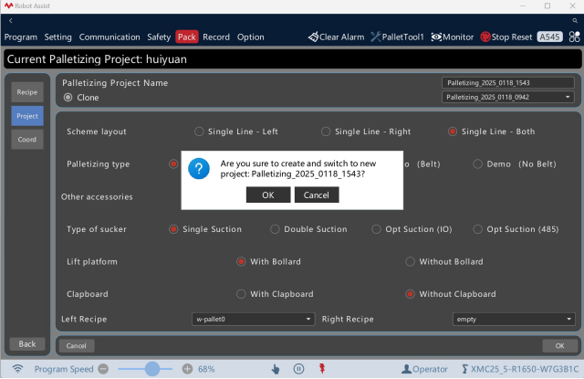
Figure Completion of the new scheme addition
2.6.2. Edit a scheme
1. Click "Scheme Name" to display the scheme list, select the required stacking scheme, click "Edit" to enter the interface for editing the stacking scheme, and modify the scheme name and configuration.
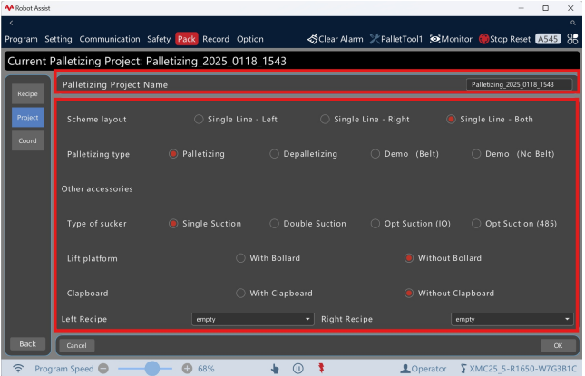
Figure Edit a stacking scheme
2. Click "Confirm", and a dialog box will pop up asking for confirmation of the update. Click "OK" to overwrite the original scheme and complete the update, then return to the scheme management interface.
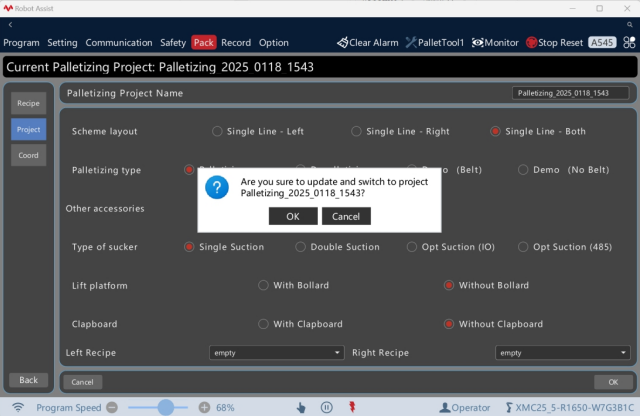
Figure Completion of the scheme editing
2.6.3. Delete a scheme
1. Click "Scheme Name" to display the scheme list. Select the required stacking scheme and click "Delete". A confirmation dialog box for deletion will pop up. Click "OK" to complete the deletion. When the currently loaded stacking scheme is deleted, after the deletion is completed, the currently loaded stacking scheme will be empty
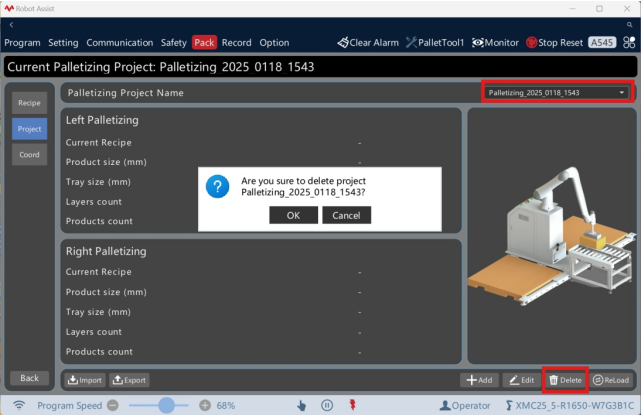
Figure Delete a stacking scheme
2.6.4. Load a scheme
1. Click "Scheme Name" to display the scheme list, select the required stacking scheme, and click "Load" to load it as the current stacking scheme.
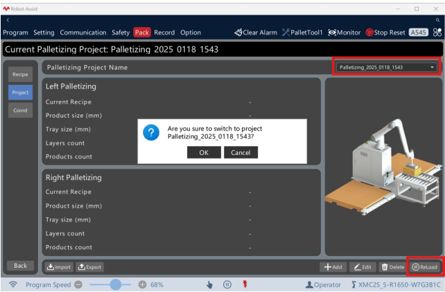
Figure Load a stacking scheme
2.6.5. Export scheme/scheme template
2. Click "Export" to pop up the import and export dialog box. Click "Open" to select the local directory you need to export to. Select the name of the scheme or the scheme template you need to export. Click "OK" to complete the export of the scheme file (.zip).
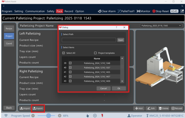
Figure Export a stacking scheme/scheme template
2.6.6. Import a scheme
2. Click "Import" to pop up the import and export dialog box. Click "Open" to select
the local scheme file (.zip) you need to import. When importing, choose "Auto Rename" or "Auto Replace", and click "OK" to complete the import of the scheme file.
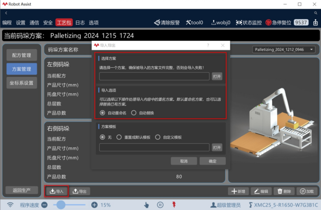
Figure Import a stacking scheme
2.6.7. Import a scheme template
1. Click "Import" to pop up the import and export dialog box. According to your needs, select "Reset to Default Template" or "Custom Template". Click "Open" to choose the local scheme template file you want to import, and click "OK" to complete the import and replacement of the scheme template file.
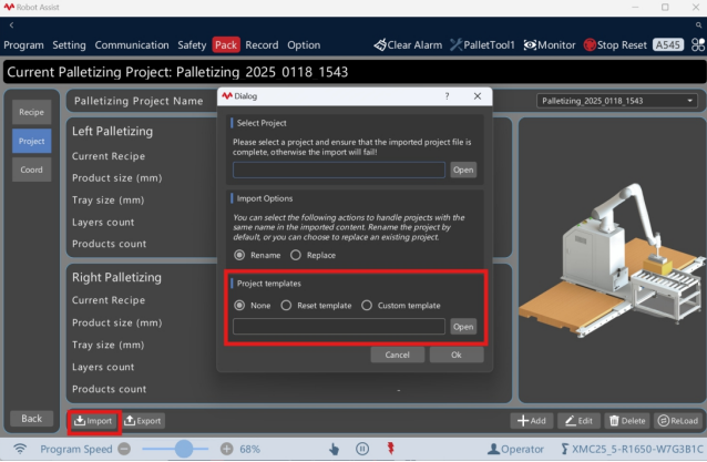
Figure Import a custom scheme template