
10. Communication
10.1 Introduction to this chapter
This chapter mainly introduces various communication settings of the xCore control system, including IO, registers, bus devices, and end-effector.
10.2 System IO
System IO is divided into two types: system input and system output. The external controller can send various commands to the xCore control system through system input, such as power-on of the motor, start-up of the program, and emergency stop reset. The xCore system can also use system output to send robot status to the outside world, such as power on/off status and operating status.
10.2.1 System input
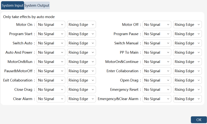
On the HMI main interface, click "Communication" -> "System IO" to enter the system IO settings interface, and click the "System Input" tab to enter the system input configuration interface, as shown in the following figure:
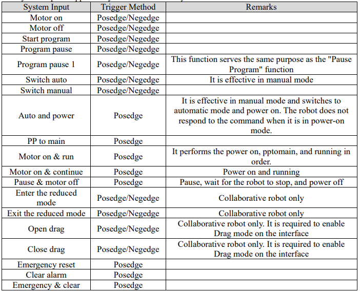
The system inputs supported by the xCore control system are as follows:

Note:
⚫ All system inputs are pulse-triggered. To ensure that the xCore system receives external commands correctly, please ensure that the pulse width of the external input is not less than 300 milliseconds.
⚫ There is a corresponding relationship between the functions that support the triggering of the posedge and negedge (power on, power off, manual mode, automatic mode, start program, pause program, enter collaboration mode, exit collaboration mode, startDrag, and stopDrag) to ensure safety, for example, the functions of "power on" and "power off" are corresponding. If DI1 is selected for "power on", DI1 cannot be used for functions other than "power off".
⚫ Most system input function is only valid in Automatic mode, and the signal from the system input in manual mode will be ignored.
⚫ It is not allowed to start the program through any ways when the register equipped with the pause function or system IO has not been reset.
⚫ The “Pause Program” and “Pause Program 1” functions serve the same purpose. Either function will pause the program upon triggering from any signal path.
10.2.2 System output
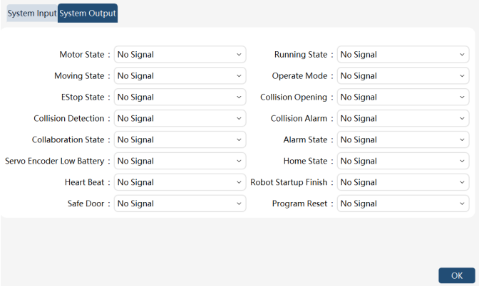
On the HMI main interface, click "Communication" -> "System IO" to enter the system IO settings interface, and click the "System Output" tab to enter the system output configuration interface, as shown in the following figure:
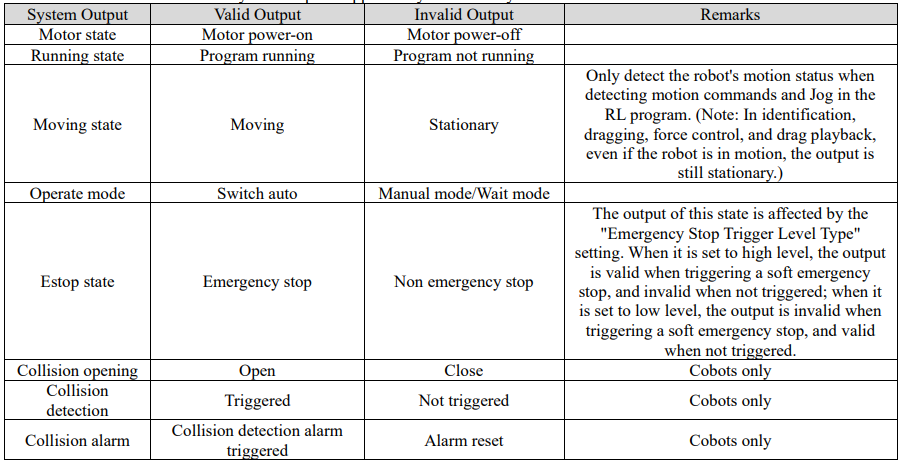
The system outputs supported by the xCore system are as follows:
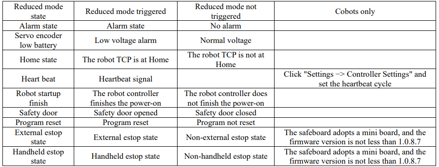
Note:
⚫ The system output status is valid in both manual and automatic modes. However, for safety and availability considerations, these signals are only to be used when the xCore is in Automatic Mode.
⚫ After an IO point is bound to the system IO, it cannot be forced to output or simulate input operations.
⚫ All other system output signals are active at a high level except the "Operating Mode" signal.
⚫ For the signal "Operating Mode", the output is at a high level in Automatic mode and low in Manual mode.
10.3 External communication
10.3.1 Overview
The xCore system provides a Tcp Socket-based external communication interface supporting both server and client through which host systems (PLC, MES, etc.) can send control commands to the robot or obtain the robot status.
10.3.2 Configurations
Before using the interactive commands, configure the parameters related to the Socket communication and enable the function. The configuration interface is located in HMI -> "Communication" -> "External Communication", as shown in the following figure:
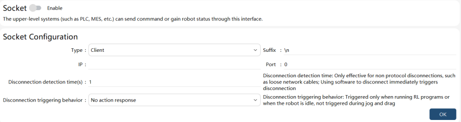
Note:
The Socket communication interface supports the robot to serve as a client or server, but only one state at a time.
When the robot is used as a client, the following parameters need to be configured:
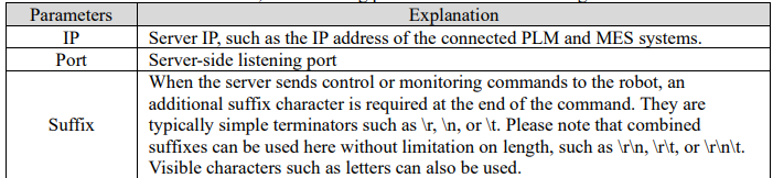
The robot used as a server supports multiple connections. In this case, please pay attention to the control sequence on the client side to avoid any conflict. The following parameters need to be configured:
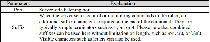
10.3.3 Interactive commands
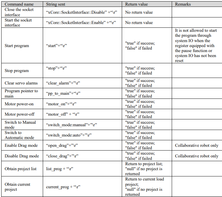
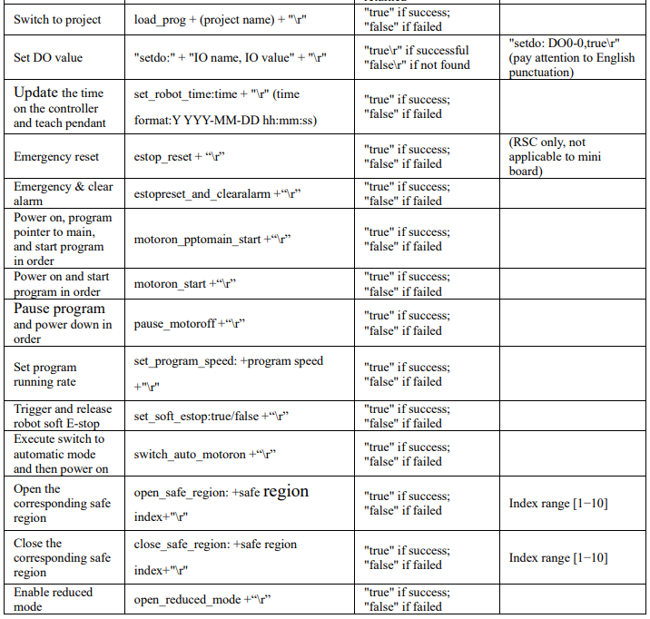
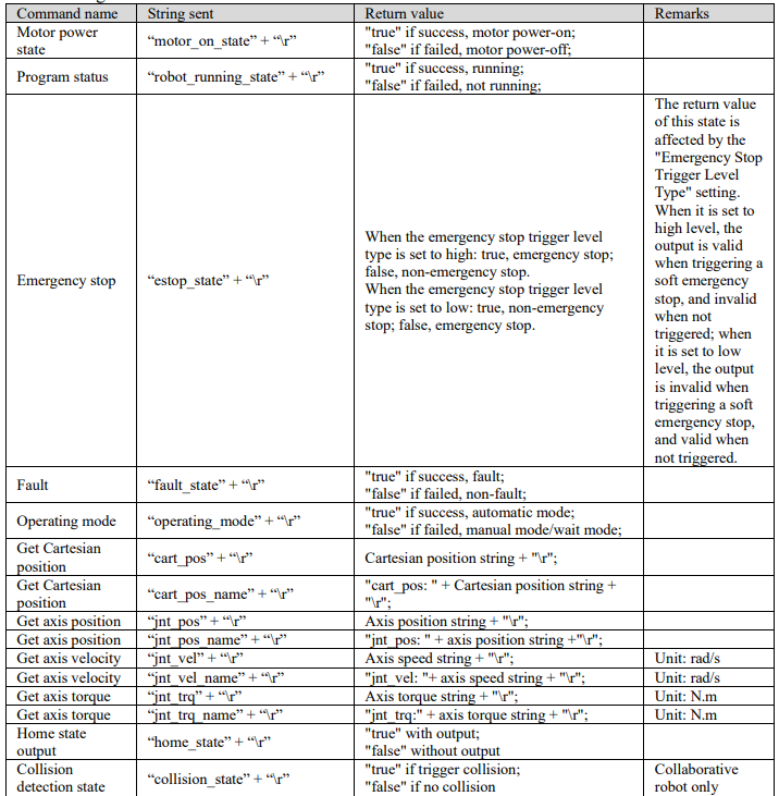
Interactive commands include control commands and monitoring commands.
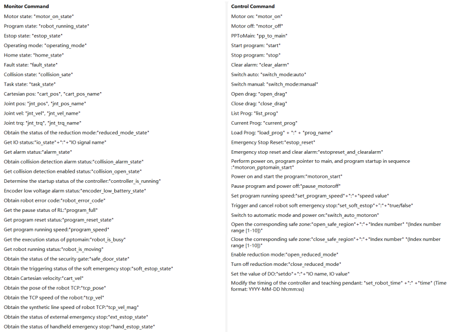
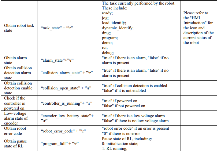
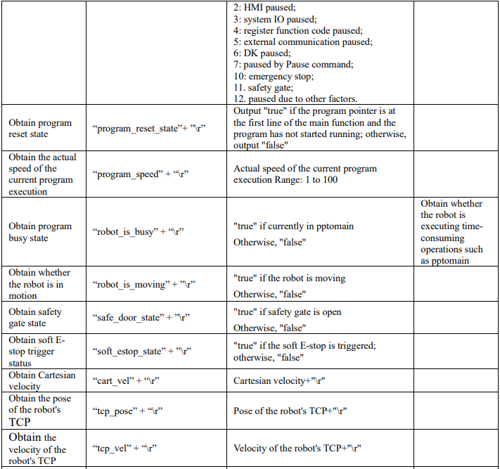
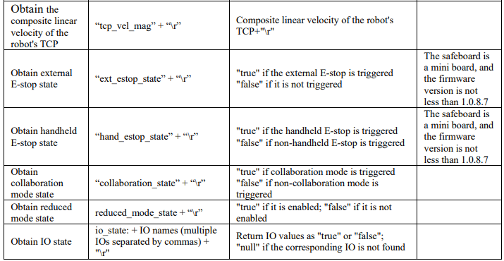
The following table gives the specific command content and format. (Assuming the user uses "\ r" as the specified command terminator, "\ r" is an escape character representing carriage return, and the decimal value is 13).
Control commands:

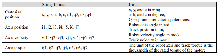
Monitoring commands:
Note:
10.4 Bus devices
10.4.1 Overview of bus devices
CC-Link, Modbus, EtherCAT, and PROFINET are supported.
CC-Link includes CC-Link devices (connected via EtherCAT) and CC-Link IE Field Basic.
EtherCAT can be used to expand bus modules such as IO modules, PROFINET, and EtherNet/IP.

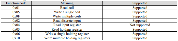
The following function codes are supported in Modbus:
10.4.2 Bus devices parameter configuration
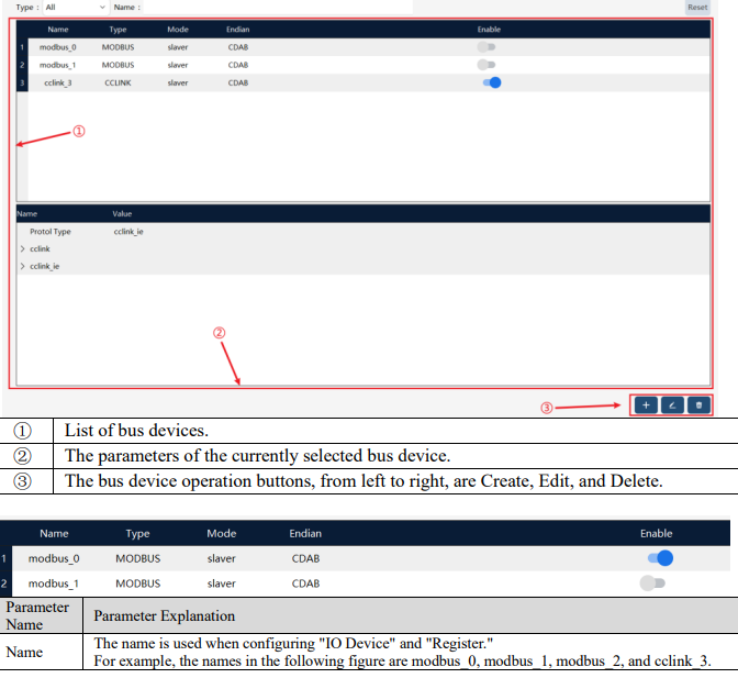
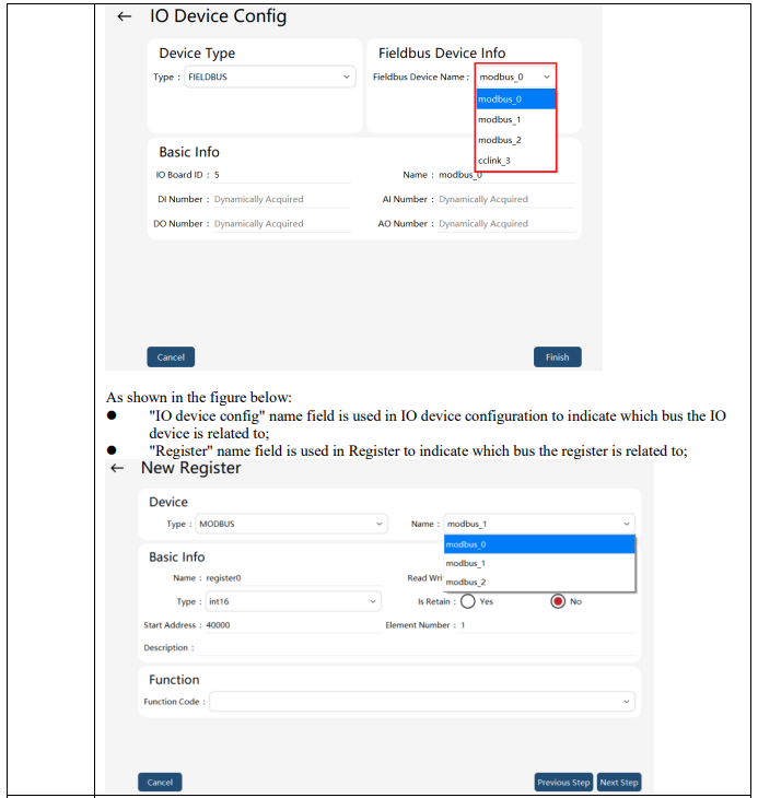
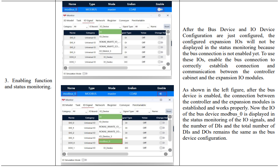
The page is at: "Communications" -> "Fieldbus Devices". The page is divided into two parts. The upper part manages all bus connections and allows for individual opening and closing operations for each bus connection. When the bus connection is closed, the IO configured for this connection will not be displayed in "Status Monitoring" -> "IO Signal". The lower part is the attribute parameters of the currently selected bus device.
10.4.2.1 Modbus communication
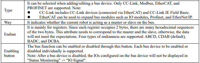
On the bus device page, click on the bottom right corner  to enter the new communication bus device page, and select the device type as "MODBUS". It supports the TCP and RTU protocol, and the device can be configured as a master or slave.
10.4.2.1.1 Modbus TCP configuration
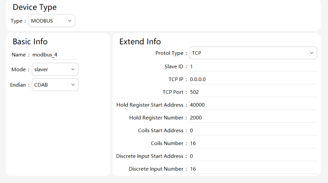
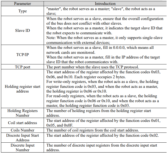
10.4.2.1.2 Modbus RTU configuration
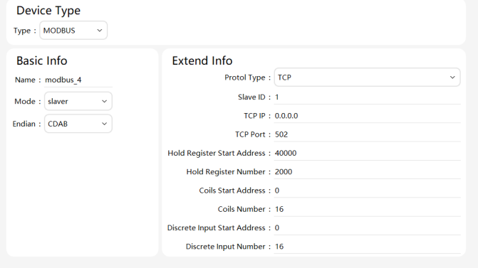
The Modbus RTU conception is partly the same as the Modbus TCP conception, which will not be repeated here. Only the differences are described as follows: RTU serial port name: Indicates the serial port medium used for bus communication. Configure it in "Communication" -> "Serial Port Configuration", including the parameters for communication.
10.4.2.2 CC-Link communication
On the bus device page, click on the bottom right corner  to enter the new communication bus device page, and select the device type as "CCLINK". It supports the CC-Link and CC-Link IE Field Basic protocol, and the device can be configured as slave only.
10.4.2.2.1 CC-Link configuration
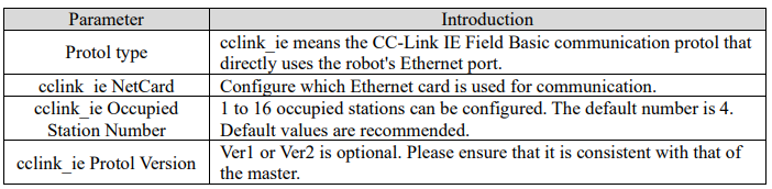
10.4.2.3 EtherCAT communication
On the bus device page, click on the bottom right corner to enter the new
communication bus device page, and select the device type as "ETHERCAT". EtherCAT can be used
to access PROFINET and EtherNet/IP gateway modules.
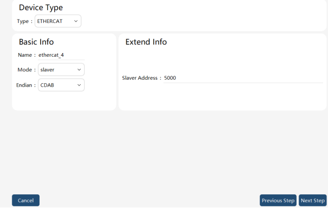
Slaver Address: The slave address number in the EtherCAT bus topology.
Note: Since the EtherCAT slave address number 1000-4000 is occupied by the robot internal devices, to avoid device address conflict, the EtherCAT slave address number of extended devices should not be less than 5000.
10.4.2.4 PROFINET communication
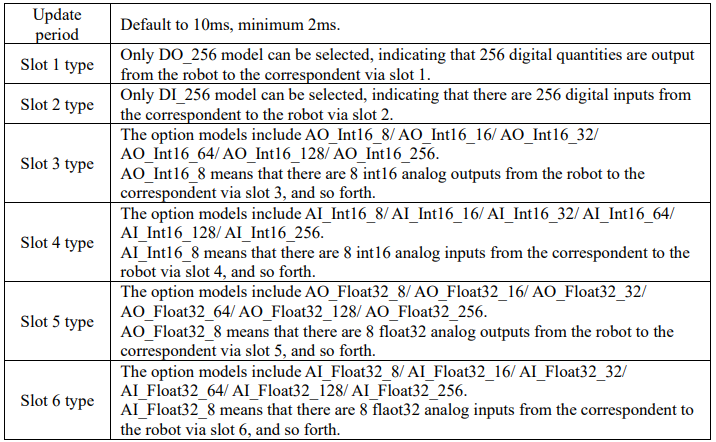
On the bus device page, click on the bottom right corner to enter the new communication bus device page, and select the device type as "PROFINET". The device can be configured as a slave only. One PROFINET slave can be configured for one robot, and multiple robots can join the same PROFINET network by modifying the PROFINET slave name to enable multiple slaves. The model selected for Slots 1-6 should be consistent with the correspondent-side configuration.
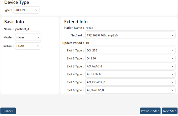
Parameter explanation:
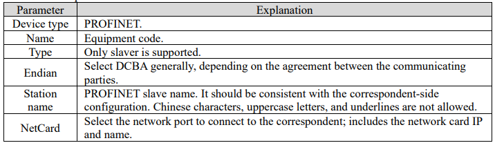
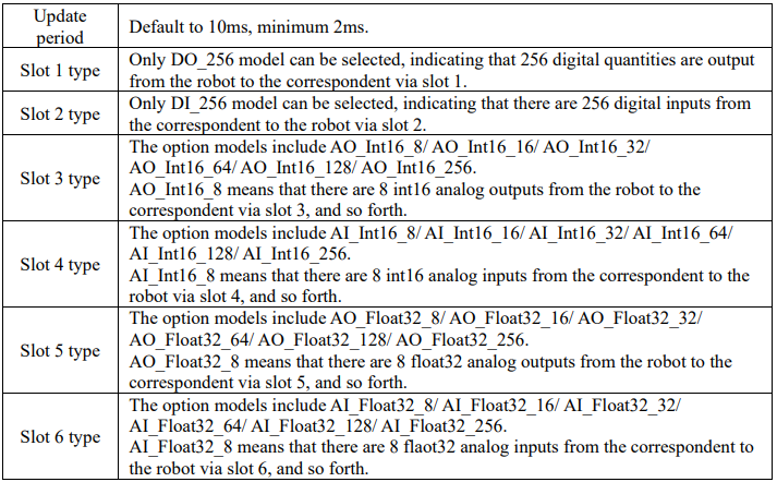
10.4.2.5 Ethernet/IP communication
On the bus device page, click on the bottom right corner to enter the new communication bus device page, and select the device type as "EtherNetIP". The device can be configured as a slave only. A single robot supports the configuration of one EtherNet/IP slave station.
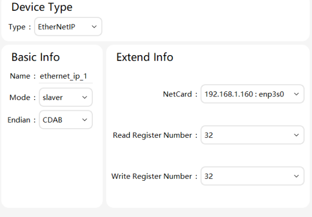
Parameter explanation:
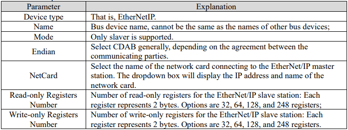
Notes:
⚫ Only one EtherNet/IP bus device is supported. Attempting to create more will result in an error 164 xCoreControl System User Manual message.
⚫ Register addresses start from 0. If 32 is selected, it indicates that the device has registers with addresses from 0 to 31. When configuring register mappings in the "Registers" interface, pay attention to the address range.
⚫ Read-only and write-only are defined from the perspective of the xCore control system: readonly registers correspond to EtherNet/IP master Output data; write-only registers correspond to EtherNet/IP master Input data.
⚫ The number of read-only and write-only registers also represents the amount of communication data. The more data, the greater the communication load. Therefore, it is recommended to select the smallest number of registers that meets the requirements.
⚫ The number of bytes for Input and Output data configured in the master station should match the number of bytes contained in the write-only and read-only registers of the slave station, respectively. Otherwise, communication may fail.
⚫ The read-only and write-only registers of the EtherNet/IP bus device are two separate data areas. The addresses for configured read-only and write-only registers can overlap.
⚫ The EtherNet/IP slave station of the xCore control system does not provide an EDS file by default. Its Input Assembly Instance ID is 1, and its Output Assembly Instance ID is 2. The master station must match these settings during configuration; otherwise, communication may fail.
10.5 Register
10.5.1 Overview of registers
The register represents the available variables within a robot, which are generally used for data exchange with external devices, so as to control the robot and obtain its status. The register can also be used as a variable in the current RL project. The register variables can be operated by commands or assignments.
Note:
⚫ The register is a concept of robots themselves, rather than belonging to bus devices. A register can be created or edited by specifying which bus device it is bound to for communication and data exchange.
⚫ Each register occupies 2 bytes. For different types of variables, the number of registers occupied is different.
10.5.2 Register parameter configuration
On the "Communication" -> "Register" page, you can view existing registers and perform Add, Edit, and Delete.
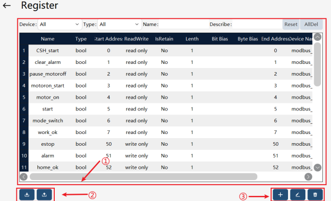


The parameters of each column in the register list are explained in the following table:
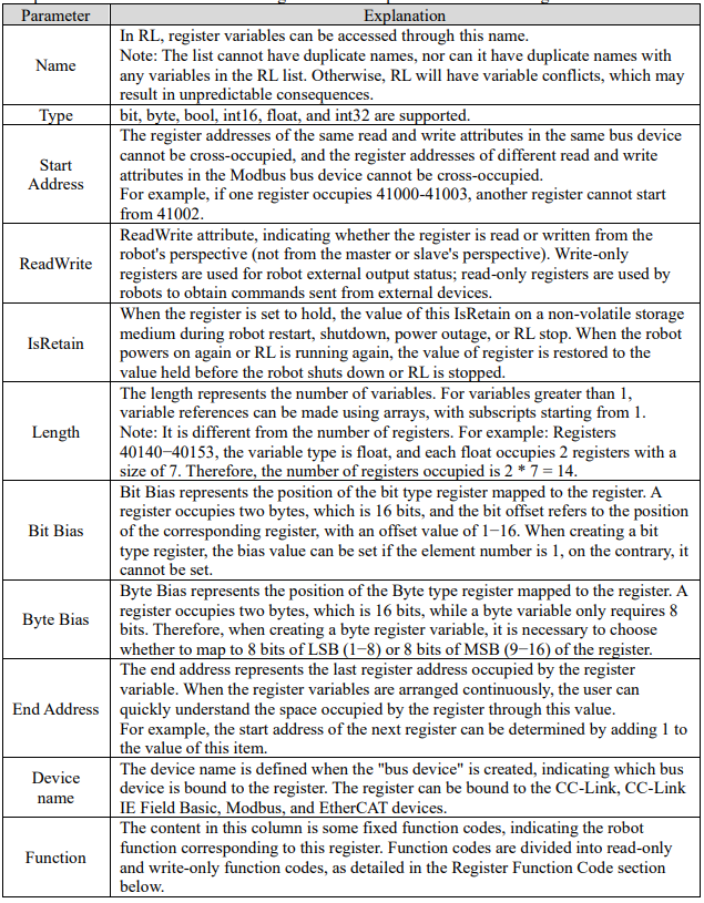
10.5.3 Register type
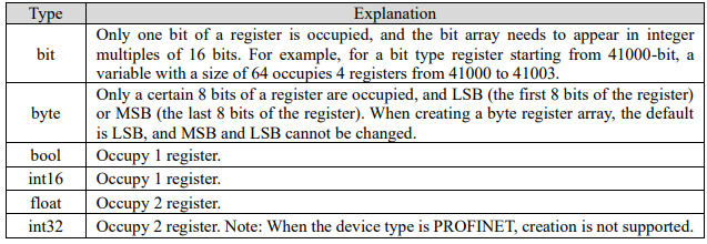
About bit type registers:
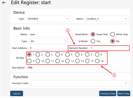

When the element number of the bit type register is greater than 1, i.e. the bit variable array, it is not allowed to set the bit bias and perform function binding. When the input of the element number in a bit type register is greater than 1, the bias option is automatically hidden, and the offset is set to 1.
About byte type registers:
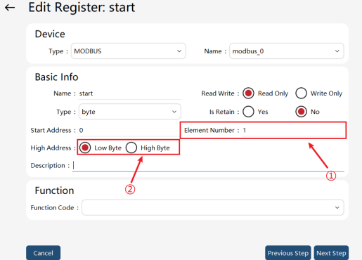

As shown in the figure above, if the element number is 1, it indicates that certain 8 bits of a register are occupied, and the byte address can be set, with optional values range of LSB (1-8) and MSB (9-16).
When the element number of the byte type register is greater than 1, i.e., the byte variable array, the byte address is not allowed to be set, with a default of LSB.
Note: It is not allowed to enable the program through the register when it is equipped with the pause function or system IO has not been reset.
10.5.4 Register function code
10.5.4.1 Read-only function code
The read-only function codes are mostly used for control signals, which are usually sent by external devices to the robot to indicate its actions. For robots, these registers are read-only. Currently supported control signals:
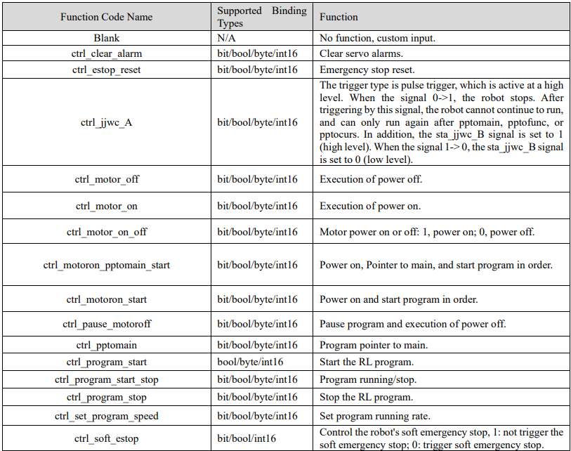
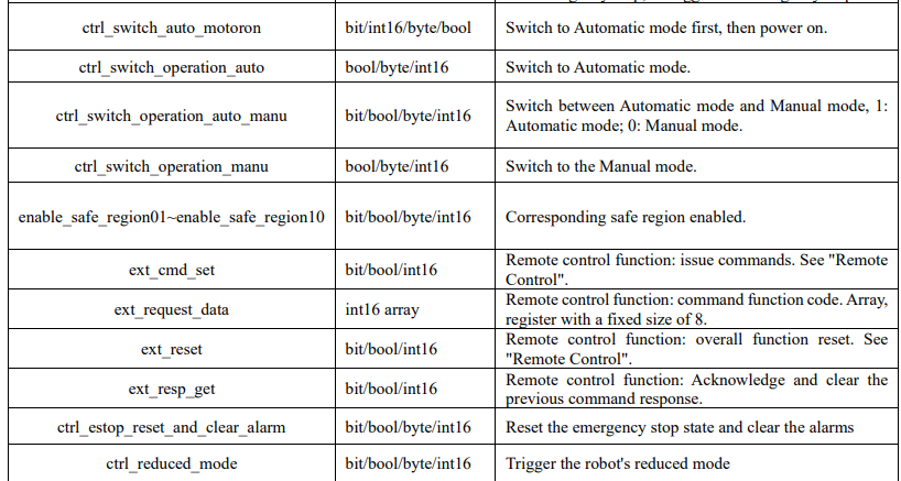
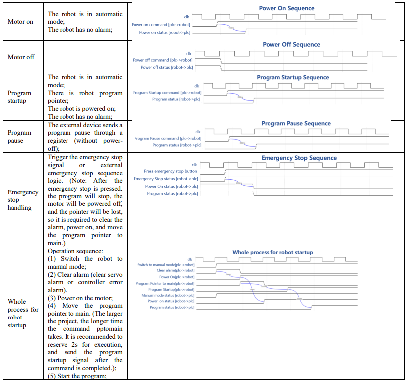
Description: All system inputs of the above system registers are pulse-triggered. To ensure that the
xCore system receives external commands correctly, please ensure that the pulse width of the external
input is not less than 60 milliseconds.

10.5.4.2 Write-only function code
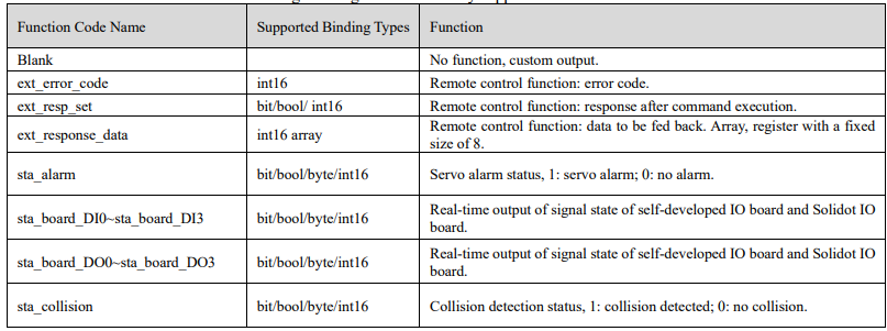
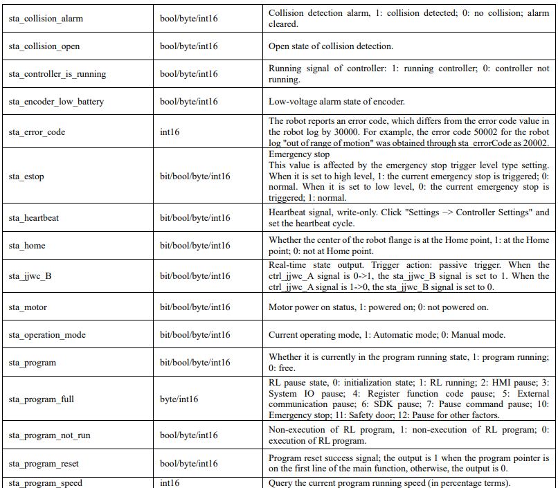
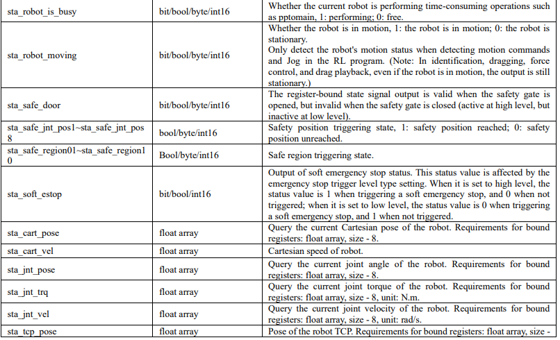
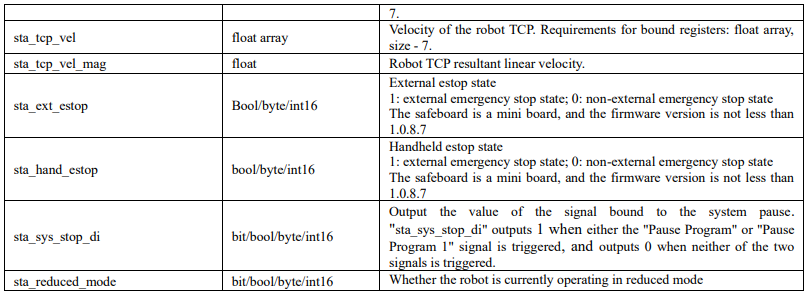
The write-only function codes are mostly used for state signals, which refer to the signals sent by the robot to the outside world for feeding back the robot's state, including the power-on state, program state, etc. For the robot, the register is write-only, and the write-only register can be bound to this state signal.
The following state signals are currently supported.
10.5.5 RL read/write register example
The control system reads and modifies the registers in two ways: command or assignment. Command provides WriteRegByName and ReadRegByName. Assignment is more intuitive and simple, using the operator "=".
10.5.5.1 Command
WriteRegByName(modbus_reg[index], rl_symbol)
Modbus-reg is the register name configured in "Communication" -> "Register", which can be offset at the first address of the corresponding register using [index]. The index range is [1, maximum register size], and the default index = 1.
The data in the control system can be output to its bound devices through registers.
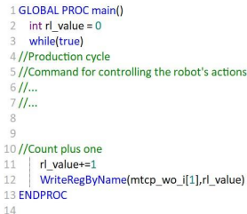
For example, "int rl_value" is defined in the control system. If you want to output it to an external device, you can specify a register, such as the first register of "mtcp_wo_i", and add a WriteRegByName command in the RL language. The value will be sent to the external device associated with "mtcp _ wo_ i".
ReadRegByName(modbus_reg[index], rl_symbol)
This command is similar to WriteRegByName, which updates the value of a register to the RL program variable. For example, it is used to control the execution process and motion parameters of RL programs.
10.5.5.2 Assignment
Directly use the operator "=". For example, "mtcp_wo_i[1] = 1" is to update the value of the first element of the register mtcp_wo_i to 1. Similarly, "a = mtcp_wo_i[1]" is to update the value of the first element of the register mtcp_wo_i to the variable a of the RL program.
10.5.6 Register remote control
Remote control is a combination function performed with registers of 7 different functions. It is used to achieve complex business logic interactions in a specific sequence. External devices can fulfill functions such as robot Jog, updating point position, obtaining robot position and status, etc. via the remote control function.
Register function
External devices use four types of registers to control the robot. These registers are read-only for the robot.
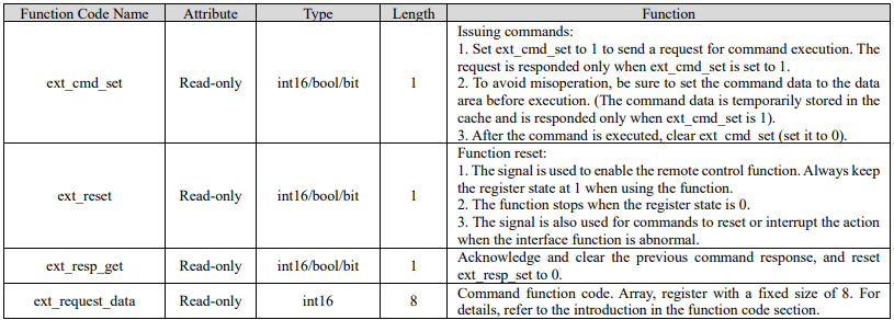
External devices use three types of registers to obtain the robot status. These registers are write-only for the robot.

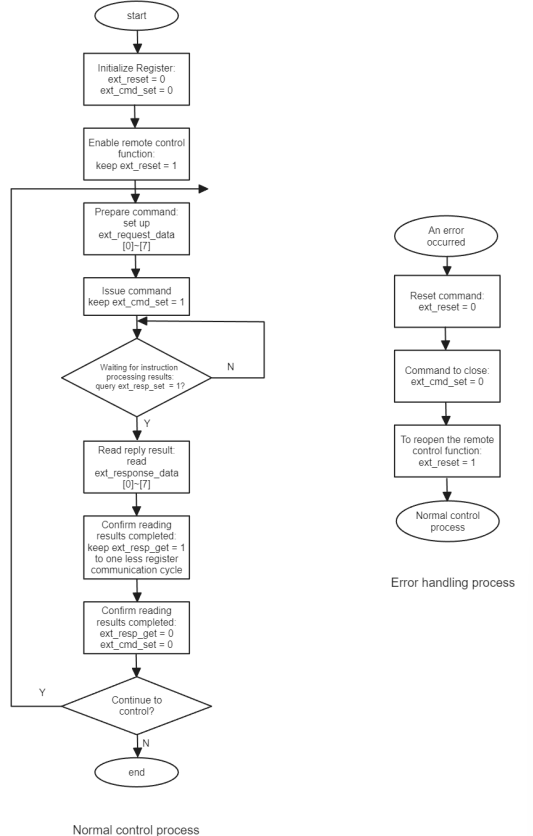
10.5.6.1 Procedure
The combined use of 7 types of registers and control flow are shown in the figure below.
10.5.6.2 Command format
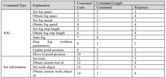
Commands and responses are implemented with 8 registers individually.
The command signal ext_request_data (eight registers occupied: reg0 - reg7) is used to specify the data area of the commands and relevant parameters. A command consists of multiple characters:
1) Character: a 16-bit register.
2) Command format: a command consists of up to 8 characters and varies with the command. The shortest command consists of 1 character.
 The response signal ext_response_data (eight registers occupied: reg0 - reg7) is used to obtain the data area of the responses. A response consists of multiple characters:
1) Character: a 16-bit register.
2) Response format: a response consists of up to 8 characters. and varies with the received command. The shortest response consists of 1 character. However, an abnormal response always occupies 3 characters.

The available command numbers are shown in the table below:
10.5.6.3 Command description
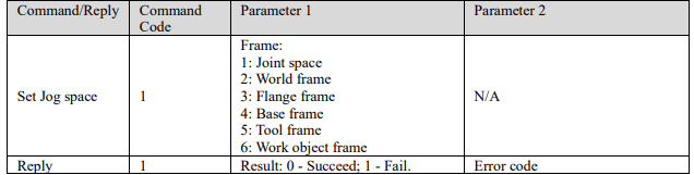
1) Set Jog space:
2) Obtain Jog space:
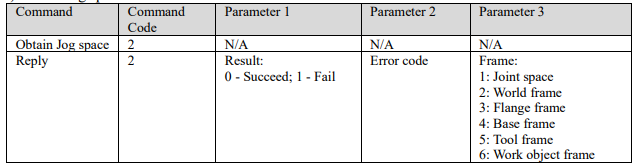
3) Set Jog speed:

4) Obtain Jog speed:

5) Set Jog step length
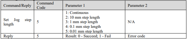
6) Obtain Jog step length:

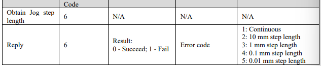
7) Start Jog:
The command is dependent on command code 1: set Jog space. In joint space, the value of parameter 1 represents the joint number (J1−J7: 1 for J1, ..., 7 for J7); in Cartesian space, it represents the (x, y, z, a, b, c, and elb) number (1 for x, ..., 7 for elb).
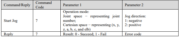
8) Stop Jog:

9) Update point position:

10) Move to point position:

11) Set current tool:

12) Obtain current tool id:

13) Set current work object:

14) Obtain current work object id:

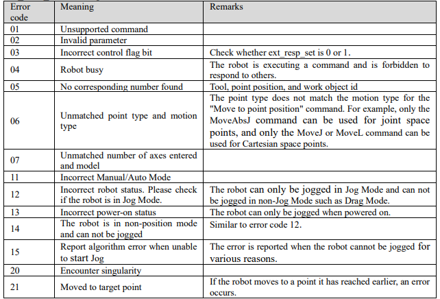
10.5.6.4 Error code
During command configuration, parameter errors, robot status mismatch, or other conditions may lead to configuration failure. Error codes can be used to check the robot's problems in this case.
The control system has three types of error codes:
ext_response_data: error code of command execution results.
ext_error_code: The command cannot be executed, for example, the robot is busy, or the remote control
flag bit is incorrect, etc.
sta_error_code: the robot error code. Read the register when an error occurs during Jog.
Normally, the error code should be used according to the following steps:
After sending the execution command (ext_cmd_set=1), first read ext_error_code. If there is no error code, read the return value of ext_response_data. If the return value is not zero, read the error code of
ext_response_data.
For motion operations (Jog and move to point position), if the above return values are both 0, read
sta_error_code to see if there is a stop in the motion caused by an error (such as singularity and overrun).
ext_error_code description:
10.5.7 Register import and export
The register import and export function can quickly copy register configurations from one robot to another robot without reconfiguring registers.
10.5.7.1 Register export
On the register page, click the button in the bottom left corner  to enter the register export interface
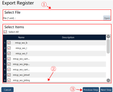

Export steps: First, enter or select the register export target file path in ①, then check the register to be exported in the register list in ②, and finally click the "Next" button in ③ to execute the export. The
exported register file can be generated under the corresponding path in ①.
10.5.7.2 Register import
On the register page, click the button in the bottom left corner to enter the register import interface
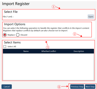

Import steps: First, select the register file to be imported in ①, then set the conflicting register strategy in ②, then select the register to be imported in ③, and finally click the "Next" in ④ to perform the import to import the selected register to the local machine.
10.5.7.3 Conflict checking during register import
The same device and register properties (read and write) cannot have the same register address. If the same, if the import option is set to not import, the original register will prevail, and conflicting registers will not be imported; if the import option is set to auto replace, the newly imported register will prevail, and the conflicting register will be overwritten. A pop-up window will prompt the user to choose whether to replace the current register.
When creating the 7 registers starting with ext: ext_cmd_set, ext_resp_set, ext_resp_get, ext_reset, ext_response_data, ext_request_data, and ext_error_code, if the register has been bound by the register address, these addresses cannot be bound by another register. When importing the above 7 registers, if the function codes have already been bound in the HMI, and the newly imported register list also involves such function codes, the newly imported ones will prevail, and the original conflicting register will be overwritten. A pop-up window will prompt the user to choose whether to replace the current register.
10.6 IO device
10.6.1 Overview
IO devices support four signal types: DI, DO, AI, and AO. Signal sources include: controller cabinet built-in, EtherCAT expansion, and field bus expansion. For industrial robots, the controller cabinet has several built-in DIs and DOs. For cobots, the base and the end-effector have several built-in DIs and DOs. For industrial robots, the EtherCAT expansion interfaces are reserved on the controller cabinet to connect EtherCAT expansion modules to generate new DI, DO, AI, and AO. The Modbus bus expansion can also be configured with IOs.
10.6.2 Parameter configuration
You can view all current IO devices on the "Communication" -> "IO Device" page, and perform operations on them such as Add, Edit, and Delete.
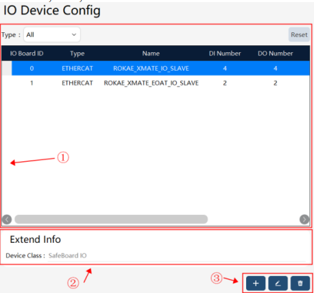

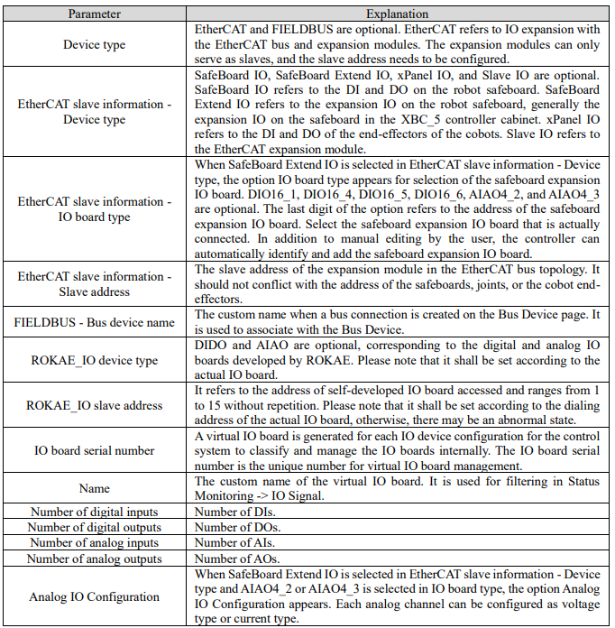
Click the Create button in ③ on the IO device configuration page in the above figure to enter the IO device (including ETHERCAT, FIELDBUS, and ROKAE _IO devices) configuration interface. The parameters on the interface may vary with the device type.
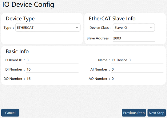
ETHERCAT-Slave IO type device parameter interface
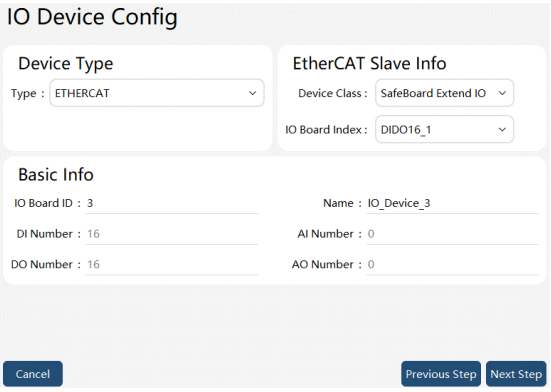
ETHERCAT-SafeBoard Extend IO-DIDO type device parameter interface
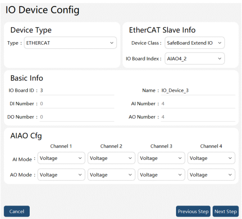
ETHERCAT-SafeBoard Extend IO-AIAO type device parameter interface
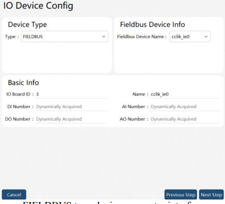
FIELDBUS type device parameter interface
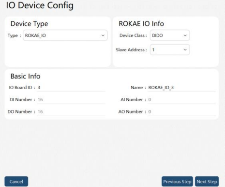
ROKAE_IO type device parameter interface
Monitor the created DI, DO, AI, and AO in Status Monitoring -> IO Signal. The IO signals can be filtered by Virtual IO Board Name. Only the IO signals currently configured on the virtual IO board will be displayed. You can also filter the signals by signal type. Only a certain type of DI, DO, AI, and AO signals will be displayed.
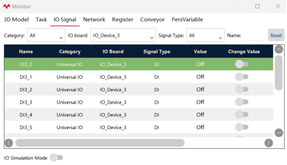
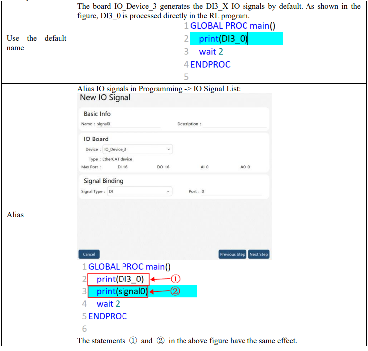
After the virtual IO board is configured, a default name will be generated for the IO signal. There are two ways to use RL: one is to use the default name; the second is to alias and use a new name in RL.
10.6.3 Modbus expansion IO example
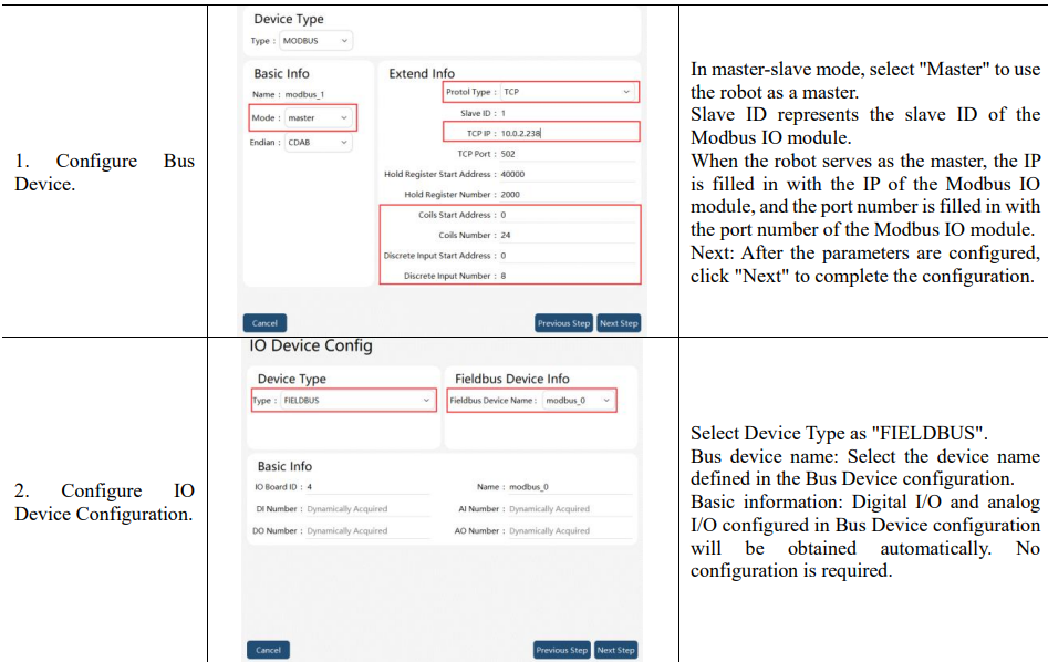
When real IO signals are required to interact with external devices, it is recommended to use an adapter module, which is connected to the control cabinet. You can contact ROKAE to obtain recommended Modbus IO modules. The module is a Modbus TCP slave and controls the robot through the coil function. The robot needs to be configured as a Modbus Master with the coil function enabled.
According to the configuration method of the field bus and expansion IOs, configure Bus Device first and then configure IO Device when using Modbus expansion module to expand real IOs.

10.7 End-effector
The xCore control system enables the manipulation of DH grippers via end-effector, with the endeffector interface supporting IO communication and RS485 communication. This functionality is exclusively applicable to the collaborative robot xMate ER series. On the HMI main interface, access to the End-effector settings interface can be obtained through the menu "Communication" -> "End-effector" menu option, as illustrated in Figure:
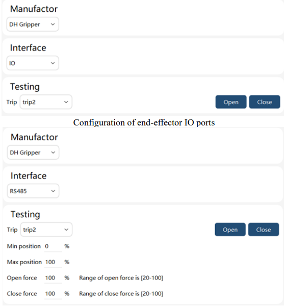
Configuration of end-effector RS485 ports
The relevant parameter settings are explained as follows:
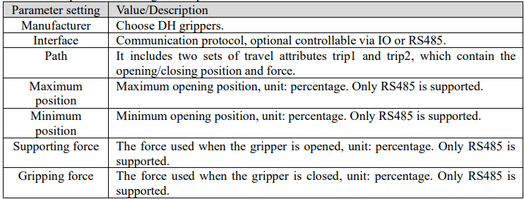
After setting the parameters, you can use the "Open" and "Close" buttons to turn the gripper on or off.
Note: RS485 supports setting of the gripper trip parameter. For IO control, the trip parameters can only be set through the DH communication adapter.
10.8 RCI settings
RCI is an external control interface, and the RCI communication setting is required before use. On the HMI main interface, you can enter the RCI settings interface through the menu "Communication" -> "RCI settings", as shown in the following figure:
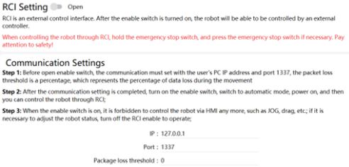
The parameters that need to be set are shown in the table below:

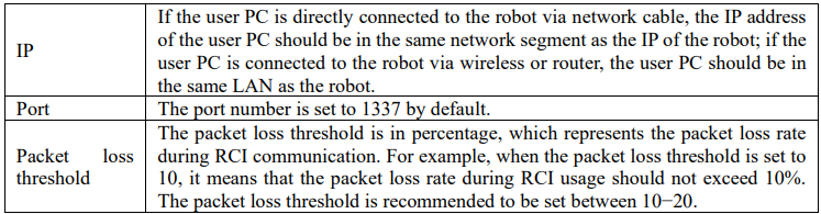
Refer to the RCI User Manual for detailed RCI usage and routines.
10.9 xPanel settings
xPanel settings are available to set the mode of the robot's end-effector, which is only applicable to the xMate CR and SR collaborative robots.
On the HMI main interface, you can enter the xPanel settings interface through the menu "Communication" -> "xPanel settings", as shown in the following figure:
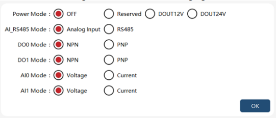
The parameters that can be set are shown in the table below:
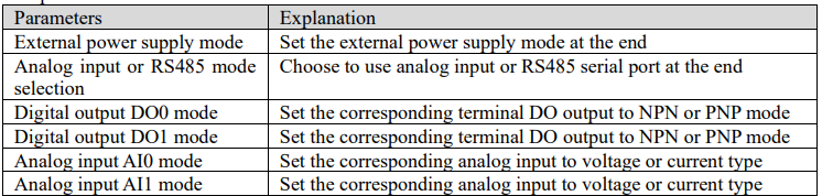
After setting the required parameters, click the "OK" button, and the settings will take effect.
Note: The voltage or current type of the external analog input signal should be consistent with the corresponding analog input mode, otherwise, unexpected errors may be caused.
10.10 Electric gripper and suction cup
10.10.1 Overview
xMate CR, ER, and SR robots support end RS485 communication and are currently compatible with multiple electric grippers and suction cups. This interface is mainly used for configuring and testing adapted electric grippers and suction cups.
Note:
⚫ The function is only applicable to xMate ER, CR, and SR robots;
⚫ The old version of the robot's end board may not be compatible with this function. Please contact the ROKAE to upgrade the board firmware;
⚫ Before using the xMate CR model, please confirm that the end parameters of the xPanel are configured correctly;
10.10.2 Configurations
On the HMI main interface, you can enter the Electric gripper and suction cup interface through the menu "Communication" -> "Electric gripper and suction cup", as shown in the following figure:
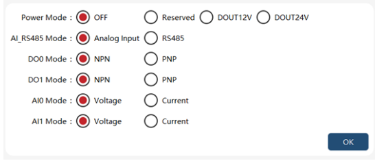
The parameter description for setting "Basic Information" is as follows:
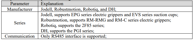
10.10.2.1 Jodell electric grippers
The "Basic Information" section allows the Manufacturer to select Jodell as the preferred option, while the Series option enables them to choose EPG. Consequently, the HMI will seamlessly transition to the testing interface of the EPG series electric gripper, as shown in the following figure:
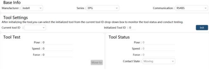
Initialization: To test an electric gripper, enter the ID of the gripper and click the "Initialize" button. If the gripper successfully detects and initializes, it indicates that the hardware connection and communication are functioning properly, allowing users to proceed or utilize it for further operations.
Tool testing: After initialization, click the "Move to" button to control the electric gripper's movement to a specified position with designated velocity and force. If the gripper reaches the desired position or encounters objects with predetermined force, it will halt its motion accordingly while displaying its contact detection status on the testing interface.
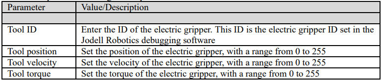
The relevant parameter settings are explained as follows:
10.10.2.2 Jodell suction cup
The "Basic Information" section includes the selection of Jodell as the Manufacturer and EVS as the Series. Consequently, the HMI will automatically switch to the testing interface specifically designed for suction cups belonging to the EVS series, as shown in the following figure: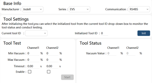
Initialization: To test a suction cup, first input the ID of the suction cup and click on the "Initialize" button. If the software prompts successful initialization, it indicates that the hardware connection and communication of the suction cup are functioning properly, allowing users to proceed to the next step or utilize it further.
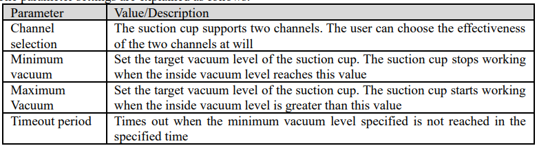
Tool testing: After initialization, adjust the suction cup parameters as required. Once all parameters have been entered, click on the "Setup" button to conduct a test on the suction cup. The parameter settings are explained as follows:
10.10.2.3 Robustmotion electric gripper
The Manufacturer selects Robustmotion in the "Basic Information" section, and chooses either RMRGM or RM-C for the Series. As a result, the HMI will automatically switch to the test interface of the Robustmotion series electric gripper, as shown in the following figure:
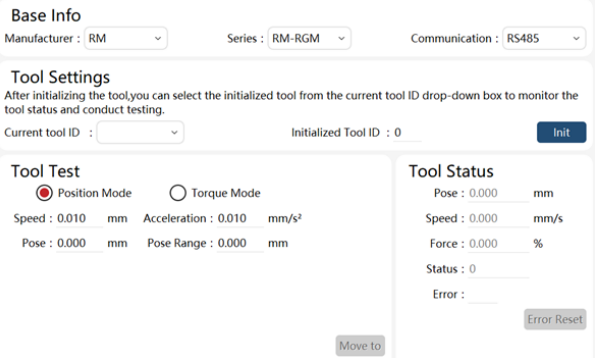
Initialization: To test an electric gripper, it is necessary to input the ID of the device and click on the "Initialization" button. If the electric gripper is properly configured and communication is established, initialization will be successful, enabling further testing and usage.
Current tool ID: This displays a list of initialized device IDs. By selecting a device with its corresponding ID, users can view its status and conduct tests.
Tool state: After successful initialization, the Robustmotion electric gripper can display various tool states including position (mm), speed (mm/s), torque (%), in-place state (1: in place), and error alarms (error code information).
Tool test: The running condition of Robustmotion electric grippers can be tested in position mode or torque mode. According to the manufacturer's instructions, position mode should be used for testing grip release while torque mode should be used for grip closure.
Position mode: Parameters that can be set include absolute positioning position (mm), speed (mm/s), positioning range (considering in-place error range, mm), and acceleration (mm/s^2), as shown above.
Torque mode: The parameters that can be set include distance (relative distance, mm), speed (mm/s), force (%), acceleration (mm/s2), positioning range (in-place error range considered, mm), and time range; as shown below:
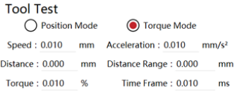
The electric gripper can move according to the set mode and parameters if clicking on the "Move to" button.
10.10.2.4 Robotiq 2F_85 electric gripper
In the "Basic Information", set the Manufacturer to Robotiq and the Series to 2F_85, and the HMI will switch to the testing interface of the Robotiq 2F_85 electric gripper, as shown in the following figure:
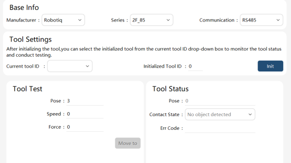
Initialization: To test an electric gripper, enter the ID of the gripper and click the "Initialize" button. If the gripper successfully detects and initializes, it indicates that the hardware connection and communication are functioning properly, allowing users to proceed or utilize it for further operations.
Tool testing: After initialization, click the "Move to" button to control the electric gripper's movement to a specified position with designated velocity and force. If the gripper reaches the desired position or encounters objects with predetermined force, it will halt its motion accordingly while displaying its contact detection status on the testing interface. The relevant parameter settings are explained as follows:

10.10.2.5 DH electric gripper
The "Basic Information" section allows the Manufacturer to select DH as the preferred option, while the Series option enables them to choose PGI. Consequently, the HMI will seamlessly transition to the testing interface of the PGI series electric gripper, as shown in the following figure:
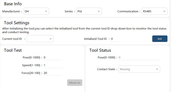
Initialization: To test an electric gripper, enter the ID of the gripper and click the "Initialize" button. If the gripper successfully detects and initializes accompanied by executing one opening and closing action, it indicates that the hardware connection and communication are functioning properly, allowing users to proceed or utilize it for further operations. Note: In the initialization process, the opening and closing of the electric gripper determines its operating range, and the electric gripper will move within the operating range.
Tool testing: After initialization, click the "Move to" button to control the electric gripper's movement to a specified position with designated velocity and force. If the gripper reaches the desired position or encounters objects with predetermined force, it will halt its motion accordingly while displaying its contact detection status on the testing interface.
Note: If the electric gripper grasps an object during movement, it will not continue to move even if the object is removed, and will only move again after a new target position is re-set.
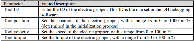
The electric gripper has five statuses, namely 0 (the electric gripper is moving), 1 (the electric gripper does not grasp the object), 2 (the electric gripper grasps the object), 3 (the object falls), and 4 (no content is displayed, that is, the current ID is not initialized successfully). The relevant parameter settings are explained as follows:
10.11 Serial port settings
Users can utilize serial ports for communication with external devices. The utilization of serial ports necessitates hardware equipment support. The XBC5 control cabinet of industrial robots features a dedicated RS-232 serial port on the cabinet body. Alternatively, users can leverage the reserved USB interface in the control cabinet and employ the USB to RS-232 interface module for serial port communication. However, this functionality is not supported by collaborative robots due to the absence of relevant hardware interfaces.
On the HMI main interface, users can access the serial port settings interface via the "Communication" -> "Serial port settings" menu, as shown in the following figure:
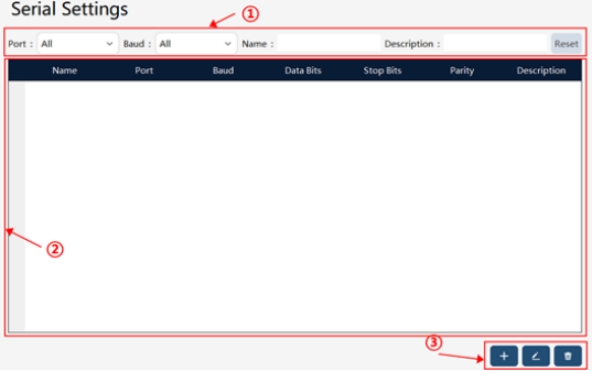

Click the "Create" button to enter the New Serial Port page, as shown in the following figure:
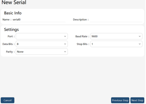
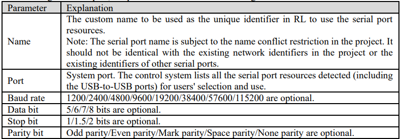
Before using the serial port, the parameters that need to be configured are as follows:
After configuring the parameters, click the "Next" button to complete the serial port configuration. At this time, use the serial port in the RL program. The serial port function includes a series of commands, please refer to the detailed description of serial port command in the RL command.
Note: Please try to ensure that the parameter settings on both ends of the serial port communication are consistent, otherwise, it may cause abnormal data transmission and reception.
10.12 Encoder
This function is part of the conveyor belt tracking function. For detailed usage, please refer to the Conveyor Belt Tracking Function User Manual.
10.13 OPC-UA
10.13.1 Overview
The OPC-UA of the xCore control system currently supports the xCore controller as the server of OPCUA communication, and supports all mandatory nodes and some optional nodes in the OPC 40010-1
OPC UA for Robotics, Part 1: Vertical Integration standard by default. For a detailed model introduction, please refer to the relevant parts of Appendix OPC-UA. In addition, it also supports userdefined variables and event upload functions.
10.13.2 Open and close
On the HMI main interface, enter the OPC-UA configuration interface through the menu "Communication" -> "OPC-UA", as shown in the figure below. You can enter the port of the OPC-UA service in the "Port" edit box above, and turn on or off the OPC-UA service through the "Enable" button.
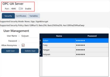
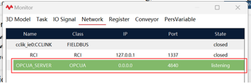
After the OPC-UA service is opened normally, you can see that the OPC-UA service is in a listening state in the network connection of the status monitoring, as shown in the following figure.
10.13.3 Safety
Click the "Safety" tab on the OPC-UA configuration interface to enter the safety configuration interface, as shown in the figure below:
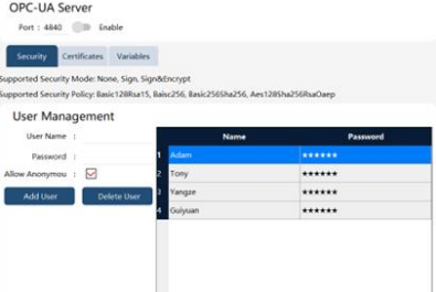
This interface is mainly used to explain and configure OPC-UA server safety policies.
1. None, Sign, and Sign & Encrypt are supported by default. Select the required mode when the client connects.
2. Four safety policies are supported by default: Basic 128Rsa15, Basic 256, Basic 256Sha256, and Aes128Sha256RsaOaep. Just select the required policy when the client connects.
3. Tick the "Allow Anonymous" check box to allow the client to log in anonymously. If it is not checked, the client can only log in with the user in the list on the right.
4. Enter the user name and password, click the "New User" button, and you can add a new user to the list on the right.
5. Select the user in the list on the right, and click the "Delete User" button to delete unwanted users.
10.13.4 Certificate
Click the "Certificate" tab on the OPC-UA configuration interface to enter the certificate configuration interface, as shown in the figure below:
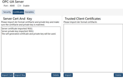
1. By default, if the OPC-UA server does not import the certificate and private key, the control system will use the self-generated certificate and private key.
2. Click the "Import Certificate" button to import the server certificate, and click the "Import Private Key" button to import the server private key. Both the imported certificate and private key need to be in der format, and ensure that the certificate and private key match. Additionally, it should be noted that the URL of the imported server certificate must be: urn:xcore.opcua.server.
3. Click the "Import" button on the right to import trusted client certificates, and click the "Delete" button to delete the selected client certificates.
10.13.5 Custom variable configuration
Click the "Variable" tab on the OPC-UA configuration interface to enter the custom variable configuration interface, as shown in the figure below:
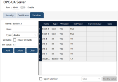
The OPC-UA communication of the xCore control system supports custom variable function, supports four types of variables: bool, int, double, and string, and supports configuring whether the client writeable properties. The specific configuration functions are as follows:
1. Fill in the attributes such as "Name", "Description", "Type", "Writable", and "Initial Value" on the left side of the page, and click the "Create" button to add a custom variable to the list on the right. A maximum of 128 custom variables are supported.
2. Click the "Delete" button to delete the selected variable in the list on the right. Click the "Clear" button to remove all variables from the list on the right.
3. Check the "Enable Monitoring" check box under the variable list on the right to turn on variable monitoring, and "Current Value" will display the value of the variable in the controller in real time.
Click the "Modify Value" button to modify the current value of the selected variable. The client can find the node of the custom variable under the CustomVariables node in the Robotics model, and perform read and write operations. On the robot side, the user can use the
ReadOpcUaVarByName and WriteOpcUaVarByName commands to read or modify OPC-UA custom variables in the RL program. For detailed usage methods, please refer to the corresponding instructions in the RL command chapter.
10.13.6 Event
The OPC-UA server supports notifying the OPCUA client of some state changes of the robot through event. The currently supported reporting events are shown in the following table.
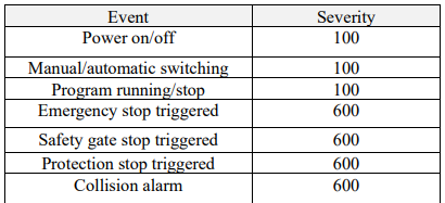
The display of client events is shown in the following figure:+
