16. Appendix
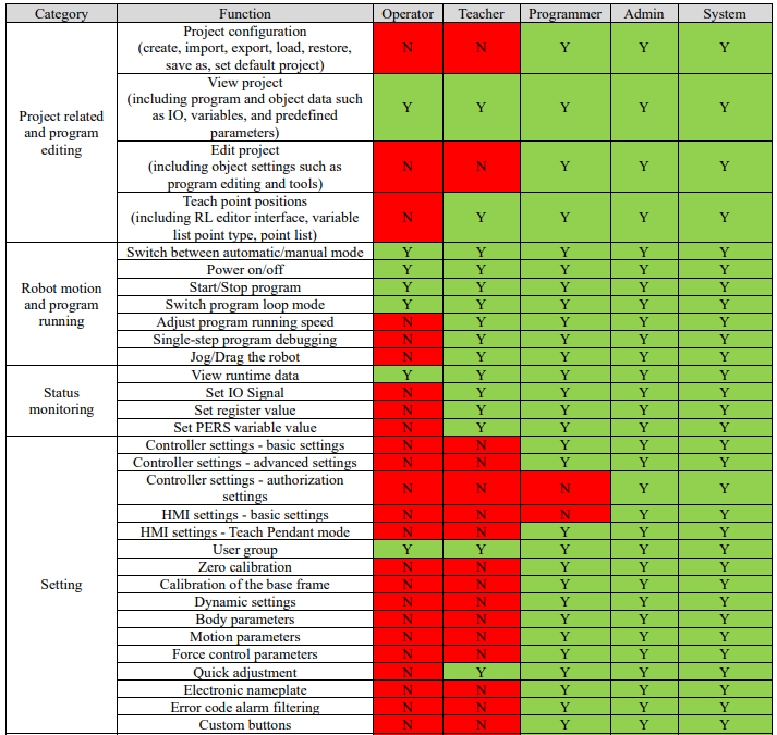
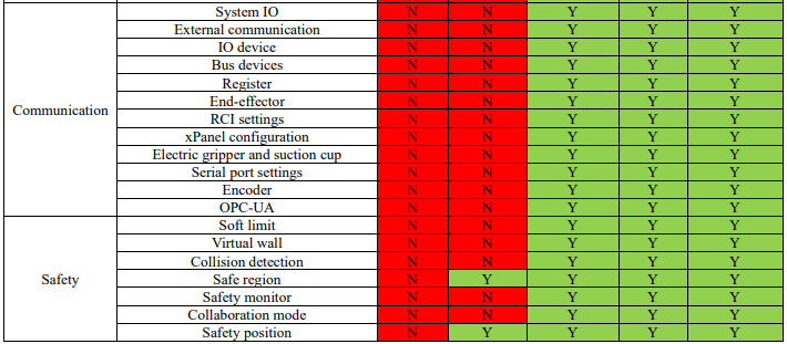
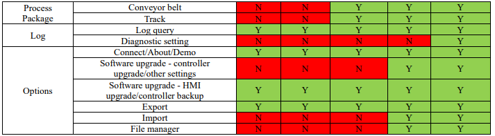
16.1 Details of user permission
16.2 Introduction of collaborative robot's end-effector handle
16.2.1 ER series
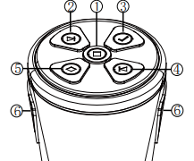
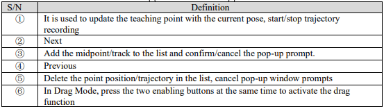
The xMate ER series robot end-effector integrates a Pilot handle with an intelligent interactive panel. In Drag Mode, the buttons on the Pilot handle can be used for quick point position teaching and continuous trajectory teaching, providing better human-machine interaction.
Definition of buttons on end-effector Pilot handle:
16.2.2 CR series
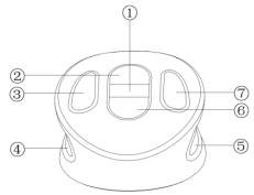
The xMate CR series robot end-effector integrates an xPanel handle with an intelligent interactive panel. In Drag Mode, the buttons on the Pilot handle can be used for quick point position teaching and continuous trajectory teaching, providing better human-machine interaction.
Definition of buttons on end-effector xPanel handle:


16.3 Point position and path teaching (based on the collaborative robot's end-effector handle)
16.3.1 Point position teaching
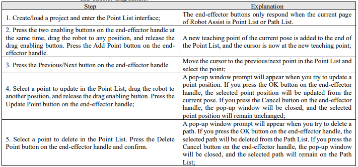
Turn on the drag enabling switch on the operation panel, and the robot is powered on automatically and enables Drag Mode. The following operations can be performed through Robot Assist and the robot end-effector drag handle:
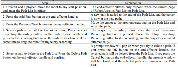
16.3.2 Path teaching
Turn on the drag enabling switch on the operation panel, and the robot will be powered on automatically and enable the drag mode. Then, perform the following operations through Robot Assist and the endeffect drag handle:
16.4 OPC-UA Robotics model
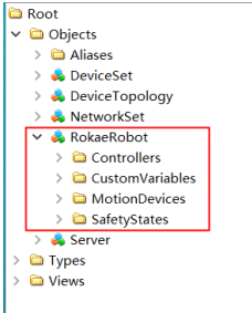
The OPC-UA server of the xCore controller system defaults to supporting all mandatory options specified in the standard of OPC 40010-1 OPC-UA for Robotics, Part 1: Vertical Integration. The toplevel directory is as follows:

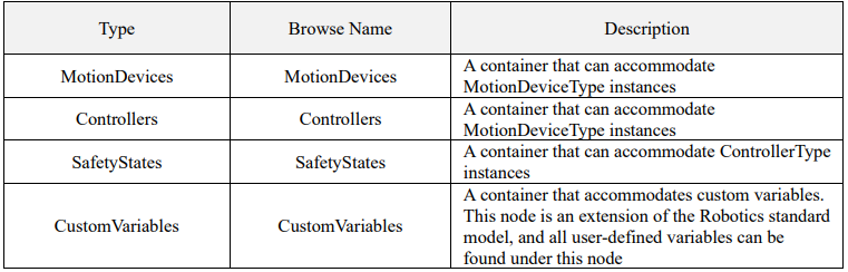
The child nodes of MotionDeviceSystem are as follows:
16.4.1 MotionDevices model
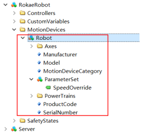

The child nodes of MotionDevice are as follows:
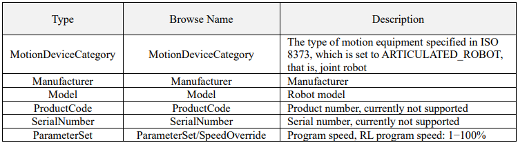
16.4.1.1 Axes child nodes
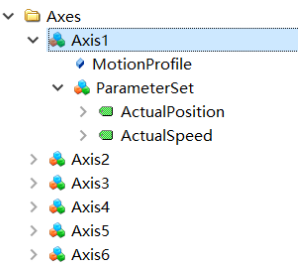

The Axes child nodes are as follows:

16.4.1.2 PowerTrains child nodes
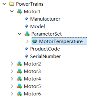

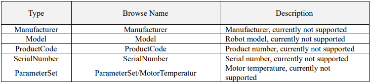
Motor child nodes are as follows:
16.4.2 Controllers model
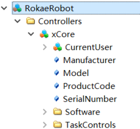

ContorllerType child nodes are as follows:
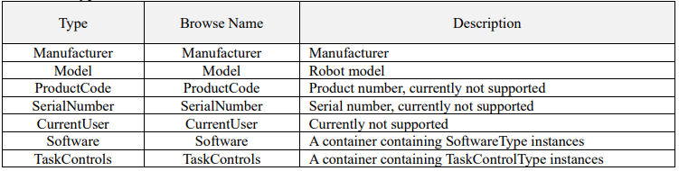
16.4.2.1 Software child nodes
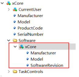

ContorllerType child nodes are as follows:

16.4.2.2 TaskControls child nodes
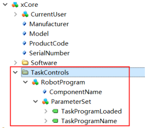

ContorllerType child nodes are as follows:
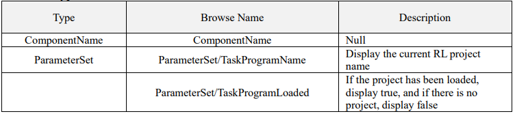
16.4.3 SafetyStates
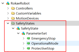

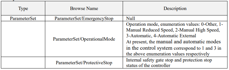
SafetyState child nodes:
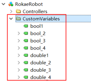
16.4.4 CustomVariables