
8. Programming
8.1 Introduction to this chapter
Industrial/collaborative robots are highly flexible production tools that can be programmed by users to meet different needs.
This chapter will introduce all aspects of programming the xCore control system. Starting with this chapter, users will gradually gain an in-depth understanding of advanced use methods such as xCore programming, setting, and communication.
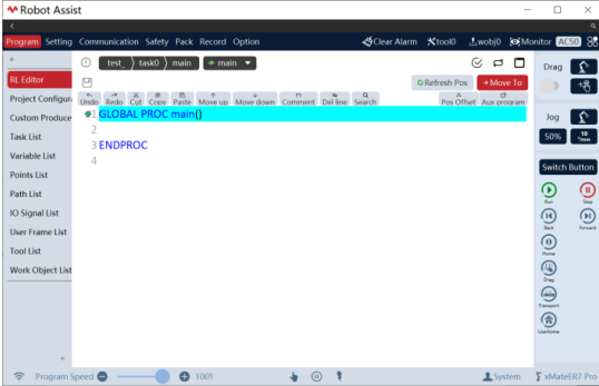
8.2 Introduction to project
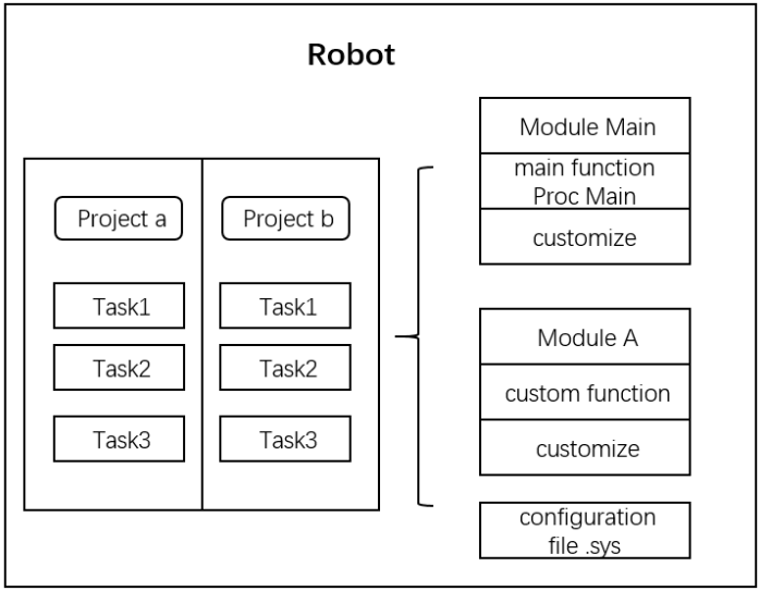
xCore manages users' programming on a project basis. A typical project includes RL program, custom user interface, tasks, variables, points, paths, IO, user frame, tool frame, and work object frame. It is divided into four levels according to the range size:

The interrelationship between projects, tasks, program modules, and functions is shown in the following:
8.3 RL editor
8.3.1 Overview
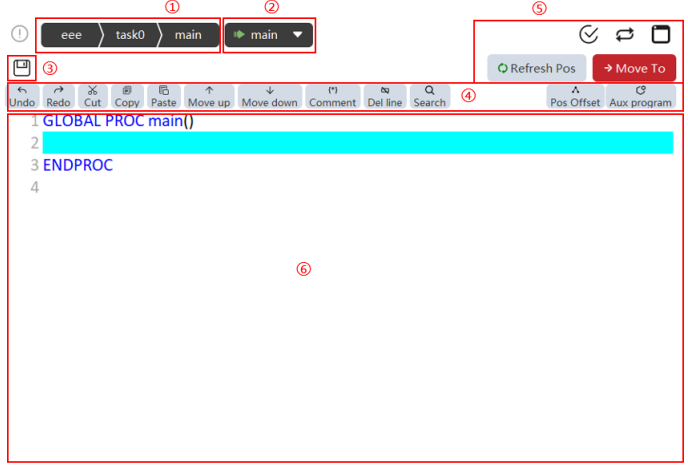
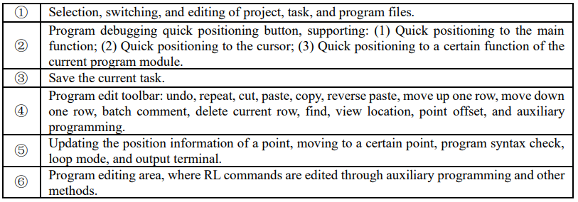
8.3.2 Tool introduction
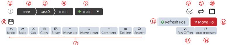
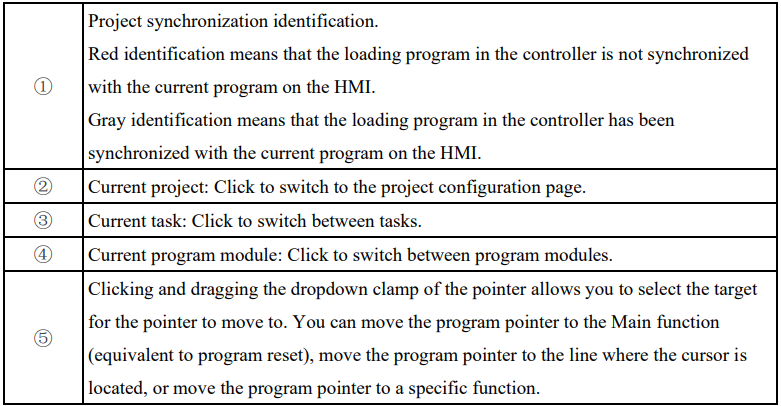
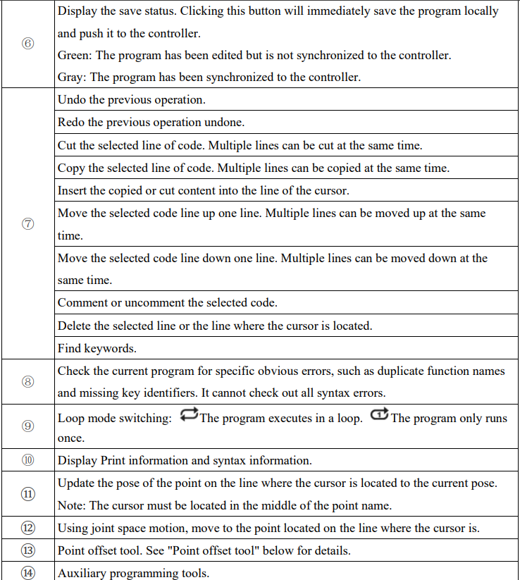
8.3.3 Auxiliary programming
The auxiliary programming interface can assist programmers in quickly building program frameworks, inserting program commands, and changing command attribute configurations. The auxiliary programming interface includes two parts: Insert Command and Attribute Settings.
8.3.3.1 Insert command
Insert Command is responsible for inserting desired commands into program text.
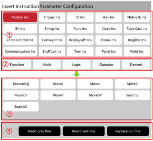
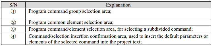
8.3.1.1.1 Example I: Insert MoveL command
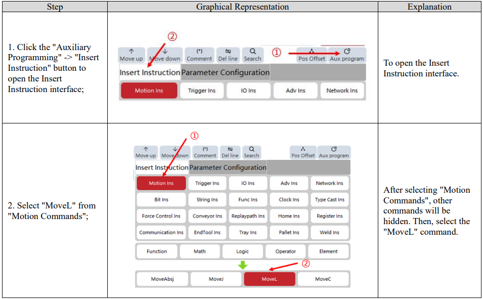
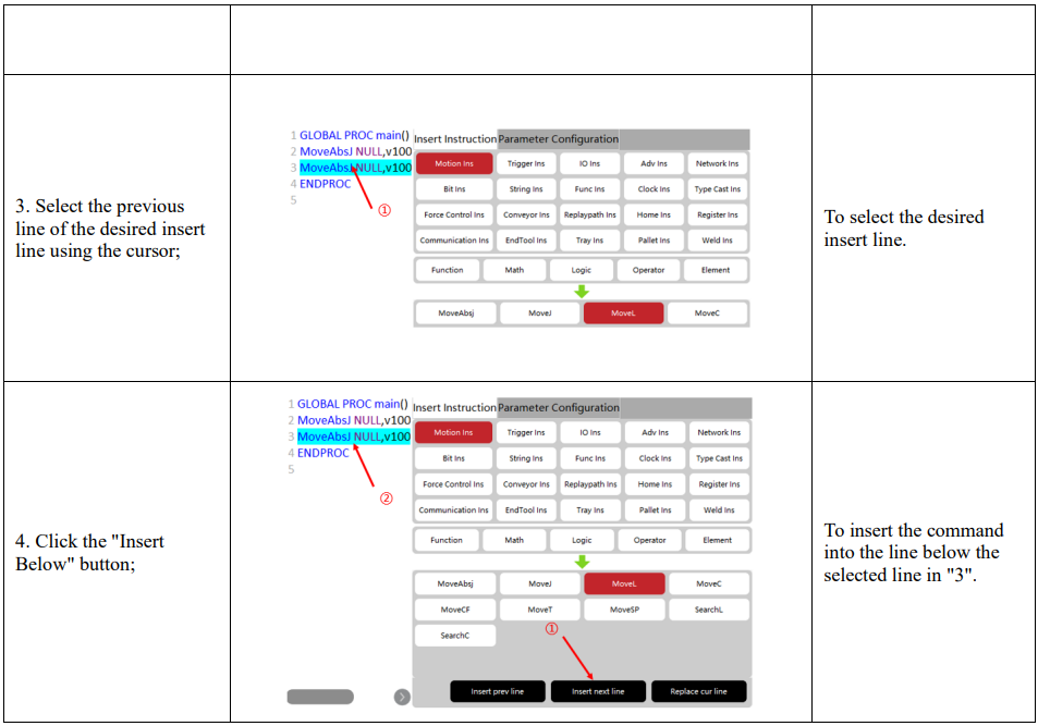
8.3.1.1.2 Example II: Insert a function
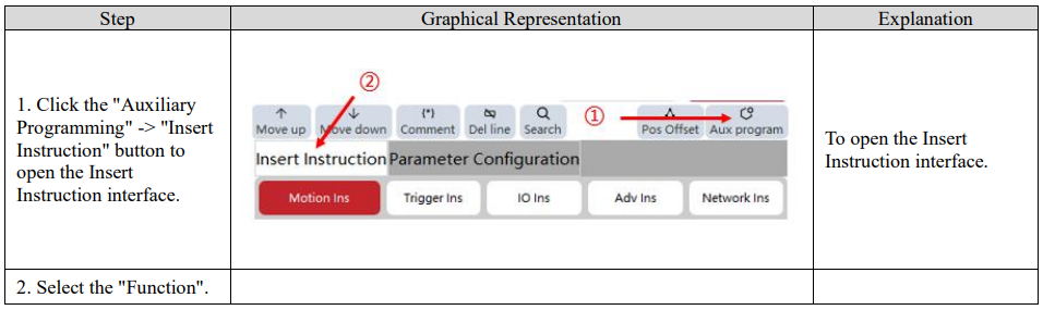
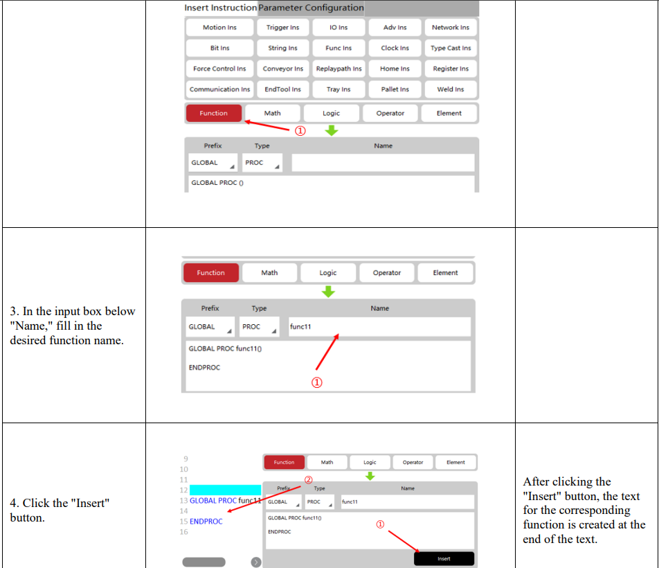
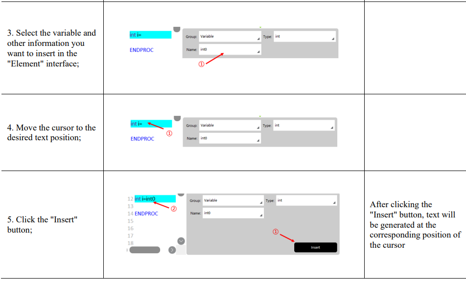
8.3.1.1.3 Example III: Insert an element
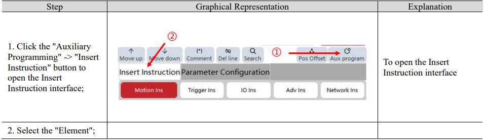
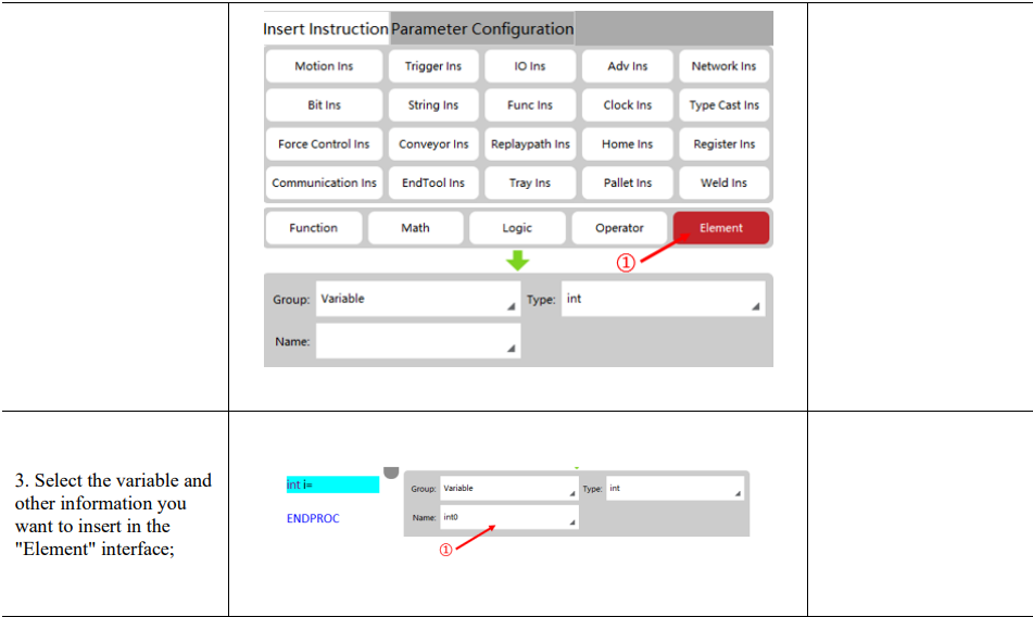
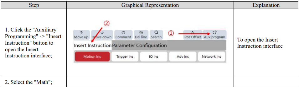
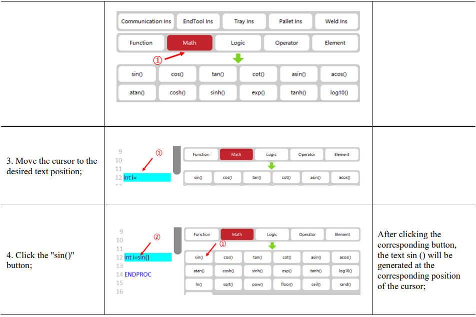
8.3.1.1.4 Example IV: Insert math/logic/operator
8.3.3.2 Attribute settings
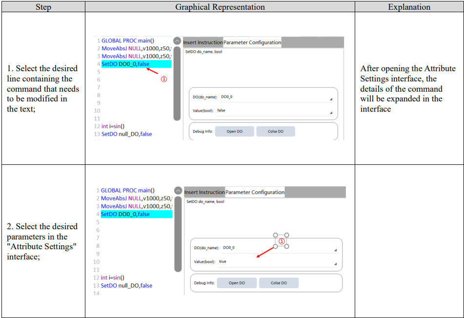
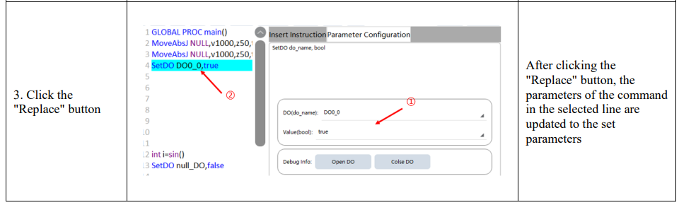
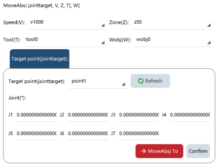
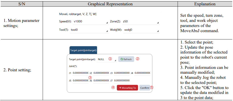
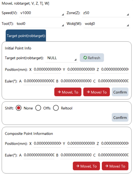
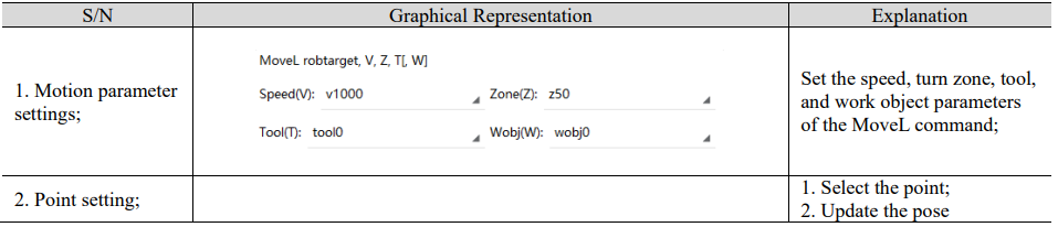
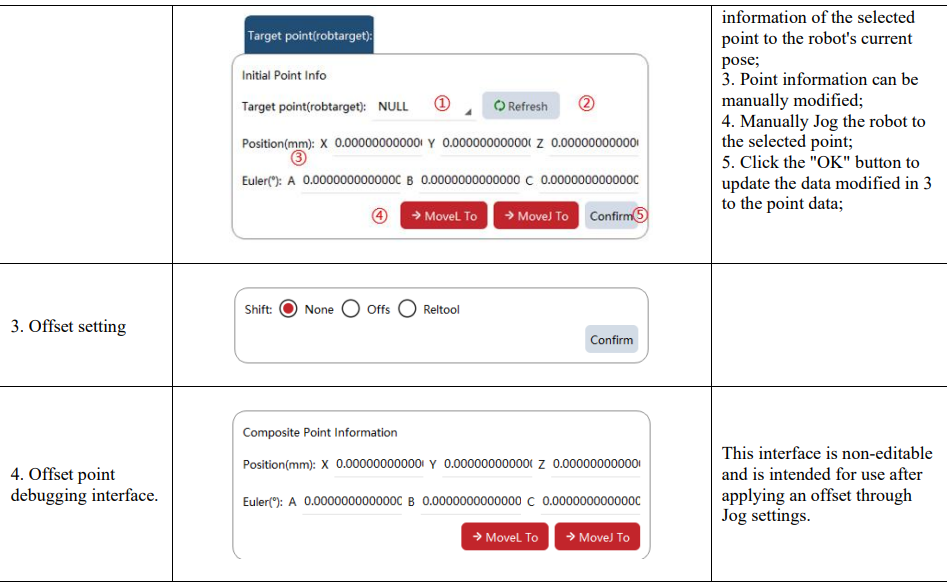
Attribute Settings is responsible for updating the command parameter information for the selected line.
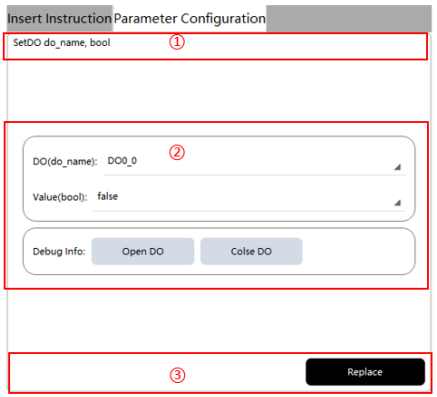

8.3.3.2.1 Example I: Configure the SetDO command attributes
8.3.3.2.2 Example II: Configure the MoveAbsJ command attributes
8.3.3.2.3 Example III: Configure the MoveL command attributes
8.3.4 Point offset tool
8.3.4.1 Overview
This tool allows for the global offset of taught points within a user-defined range of motion commands in the RL program.
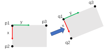
When the work object is required to be translated only, the parallel offset is used, and only the xyz values are adjusted. When you want to adjust both the position and attitude of the work object, after the "Orientation Variable" is turned on, the orientation values ABC will also be adjusted.
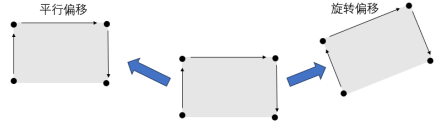
Principle: Calculate the relationship between the original frame and the offset frame through 6 points including p1, p2, p3, q1, q2, and q3. When "Pose Variable" is not turned on, only p1 and q1 need to be set.
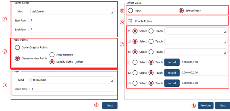
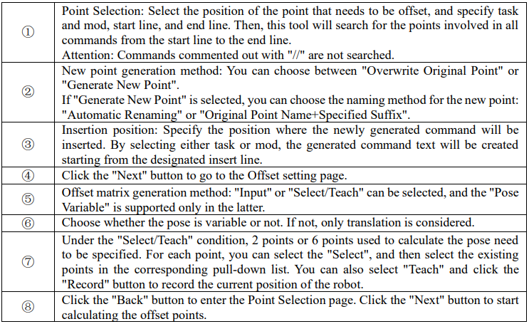
8.3.4.2 Parameter introduction
Use restrictions:
1. It is recommended to keep the number of offset points per time within 1000, otherwise, interface freezing or loss of points may occur.
2. When the system calculates an offset point, it will automatically check whether the point is reasonable, and if not, an error message will be displayed, and the generation of commands will fail. But the points before the unreasonable points will still be generated. Cause of point unreasonableness: ① Parameter error ② Singular position ③ Point unreachable ④ Other errors.
3. If there is no point between the start line and the end line of the specified mod, an error message, "No point to be offset found", will be reported.
4. The robot needs to be connected when this tool is used, otherwise, an error message of "robot communication error" will be reported.
5. The angle between the vectors formed by any two points of p1, p2, and p3 shall be greater than 1°, otherwise, it will be judged that the three points are collinear and an error message of "reference point error" will be reported; The same applies to q1, q2, and q3.
6. The point name in the command needs to be consistent with that in the point list (case-insensitive), otherwise, an error message of "point xxx not found" will be reported.
7. When the tool page is open, and when you perform operations such as adding or removing tasks, adding or removing points, editing RL, and switching between projects on the "Task List", "Point List", and RL editing pages, this tool will not automatically refresh. It is necessary to close and reopen the tool page manually for refreshing this tool.
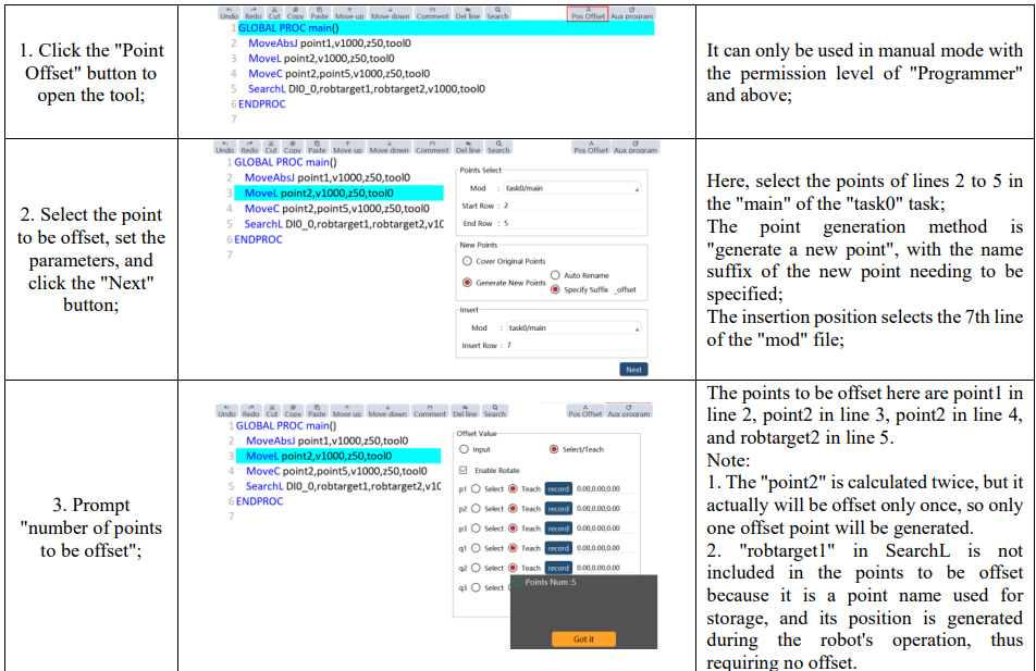
8.3.4.3 Operation examples

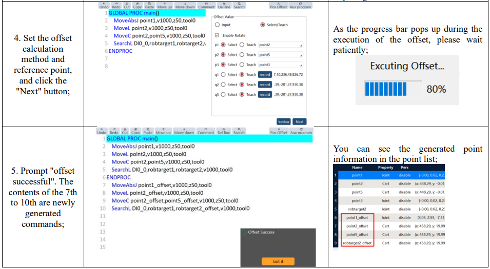
8.3.5 Move to function
"Move to" Function: This function enables the robot to move to the selected point by executing a series of operations;
8.3.5.1 Operation examples

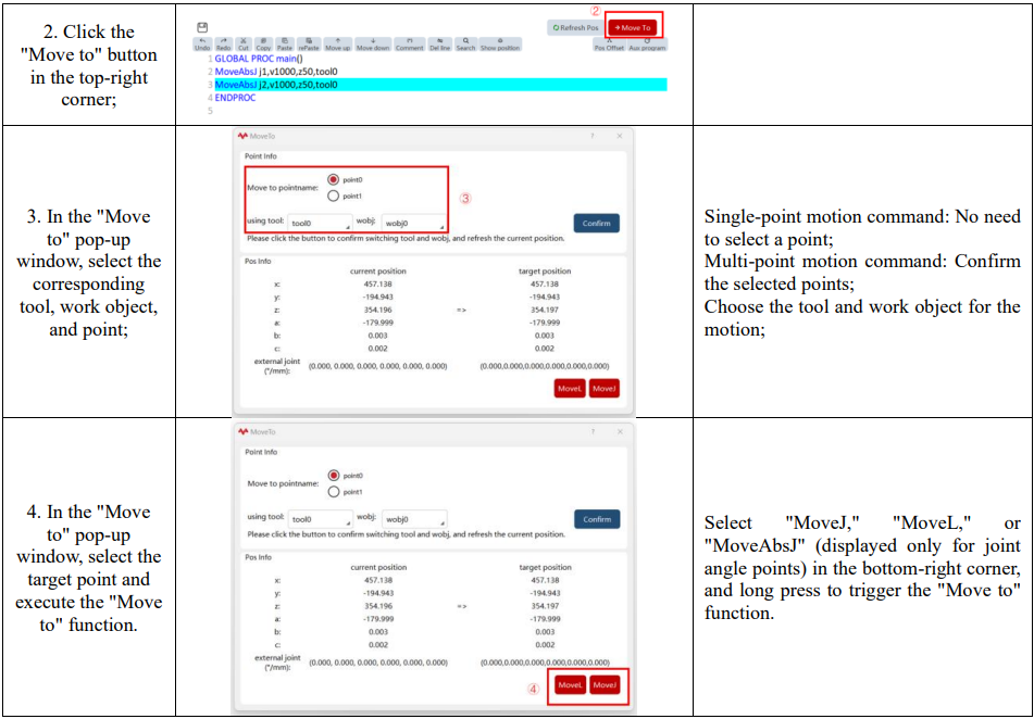
8.3.6 Show position function
8.3.6.1 Overview
"Show position" function: This function is primarily designed for users to identify the current stop position of the robot and determine which line of the RL program it corresponds to.
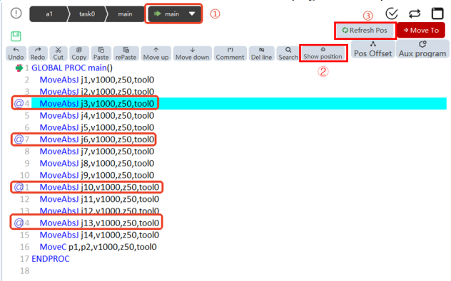
Triggering the view location function can be done in the following ways:
1. Clicking the "PPToMain" button;
2. Clicking the " Show position " button;
3. Clicking the "Refresh Pos" button;
When the "Show position" function is triggered, a  symbol will be displayed on one or more lines in the RL program interface, indicating that the robot's current position matches the point position used on those lines.
8.3.6.2 Show position parameter settings
Refer to the "Settings" -> "HMI Settings" -> " Looking Position Params" to configure the tolerance range between the robot's actual position and the point positions in the RL program;

8.4 Project configuration
The Project Configuration interface is used for the relevant configuration of the current project.
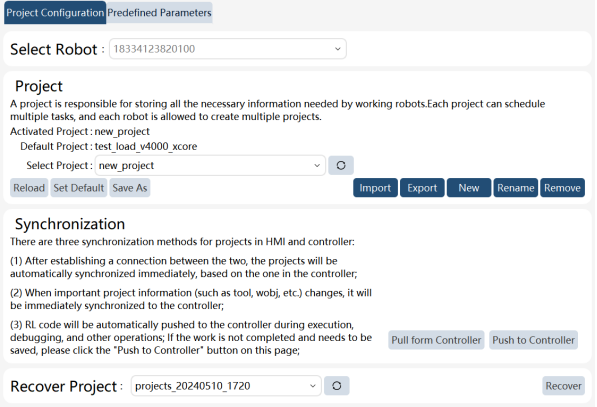
8.4.1 Robot selection
When the RobotAssist software is running on the PC side and the robot is not connected, if you want to edit the RL project offline, you can select a previously connected robot here, and the system will switch and display the project data of the robot.
When the RobotAssist software is connected to a robot, the currently connected robot is shown here.
8.4.2 Project
Reload: Reload the selected project.
Set as default: Set the selected project as the default project, which can be automatically loaded when the robot is started up.
Save as: Save as a selected project and push it to the controller.
Import: Open the Import Project page and select parameters such as the project system and project path to be imported.
Export: Open the Export Project page, select the project you wish to export and specify the export path. The system supports exporting projects in formats compatible with xCorev2.2 and earlier, as well as in the xCore3.0 format.
New: You can click it to create a new project. The project name can only be a collection of letters, numbers, and an underscore.
Rename: Rename the currently selected project.
Delete: Delete the currently selected project.

8.4.3 Synchronization
There are three ways to synchronize the project files in HMI with those in the controller:
1. After the connection between the two is established, their project files will be automatically synchronized immediately, with the project files in the controller taking precedence;
2. When the important information of a project (such as tool and work object) changes, this change will be synchronized to the controller immediately;
3. The RL code will be automatically pushed to the controller when performing operations such as operation debugging. If the work is not completed and you need to save it, you can click the
"Push to Controller" button on this page.
"Load from Controller" button: The teach pendant will re-synchronize and load the projects from the controller, and this operation will directly overwrite all current projects in the teach pendant.
"Push to Controller" button: The teach pendant will synchronize its current projects to the controller
8.4.4 Restore project
When the project is modified, the controller will back it up periodically. In the drop-down list, select a backup project named by time and click "Restore" to restore the backup project. Click to refresh
the backup project list.
8.4.5 Predefined parameters
The predefined parameters include the basic frame parameters, as well as a train of standard speed and turn zone parameters, and these variables are used as parameters for the RL command. You can view the physical meanings of the variables on this page, but they are not allowed to be edited currently.
8.5 Custom production
The custom production interface provides a simple and intuitive interactive mode for users. Users can create a concise monitoring and interaction interface simply by selecting registers, DI/DO signals, points, and project variables of interest. The functions supported by this interface include: displaying and editing registers, displaying the status of DI signals, enabling DO signals, updating point positions, and displaying and editing project variables.
8.5.1 Overview
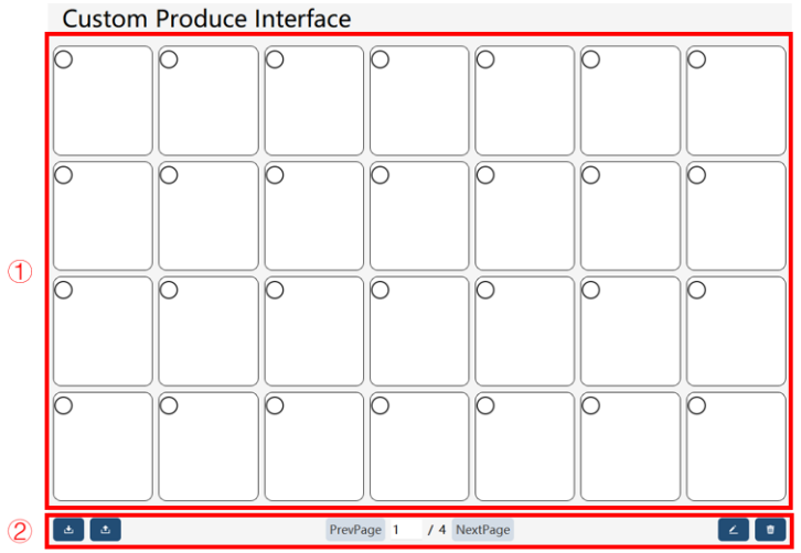

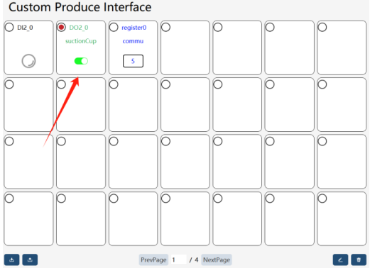
The Operation/Display Panel contains multiple production task controls, which can be imported, exported, edited, and deleted through the buttons below.
The control contains three parts, among which the top part shows the control signal name, the middle part refers to the control's label text (customized by users), and the bottom part is available for users' operations/displays on the control. Various controls provide different interactions.
8.5.2 Basic operations
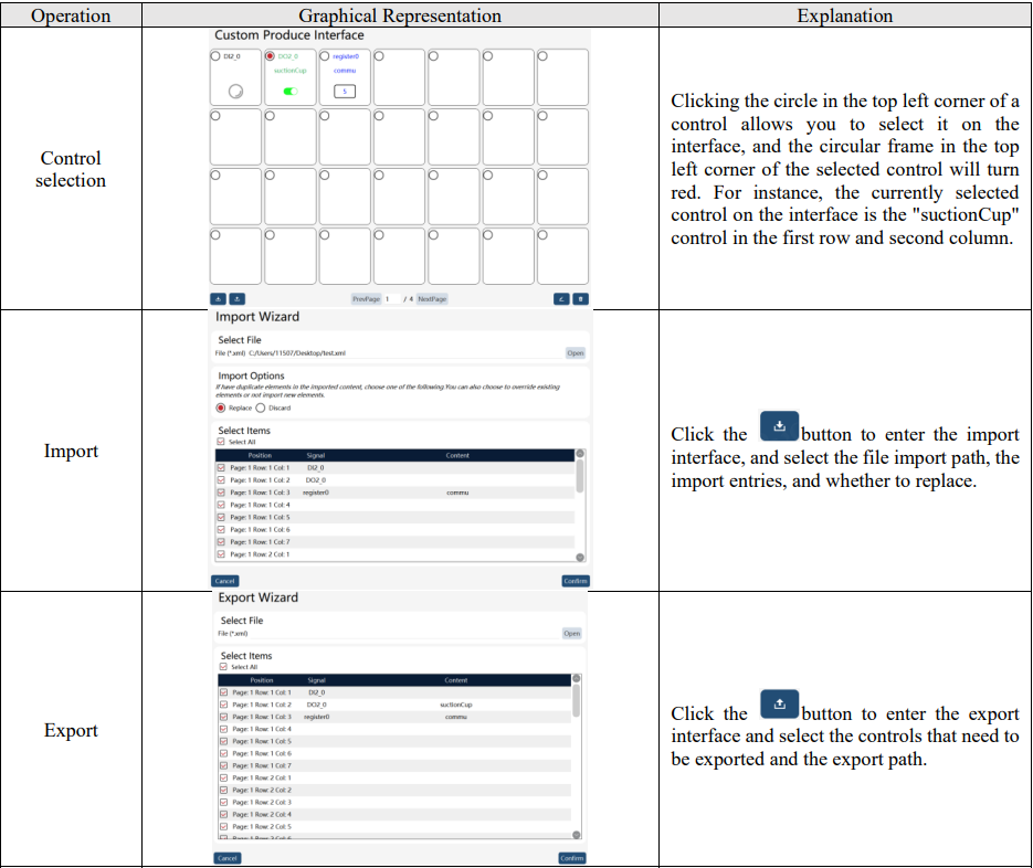
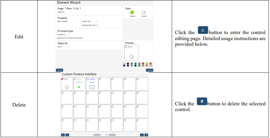
8.5.3 Control introduction
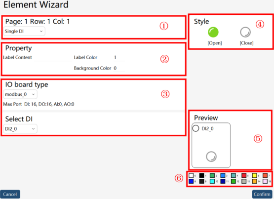
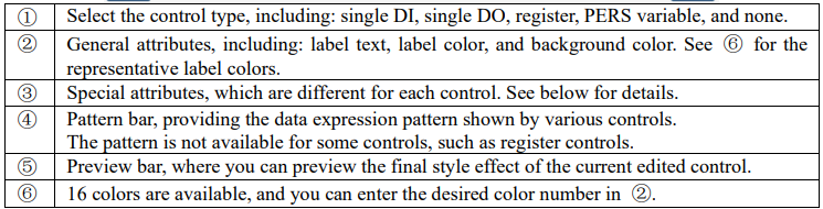
With four types of controls offered by the custom production interface, users can develop the interface style suited for the production conditions. They are the single DI control, single DO control, register control, and PERS variable control, respectively. The control editing page is shown below.
8.5.3.1 Single DI control
Single DI control can be used for DI display. Types of optional IO boards include: (1) IO devices configured by users on the IO Device interface; and (2) User DI signals configured by users in the project's IO signal list.
The editing interface is shown below:
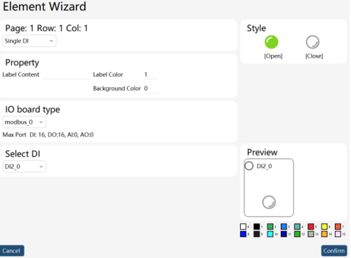
When the selected DI is True, the "On" icon under the control pattern is green. When the IO is False, the "Off" icon under the control pattern is gray. The single DI control is not available for control interaction and is only used for DI status display.
8.5.3.2 Single DO control
Single DO control can be used for DO signal display and settings. Types of optional IO boards include: (1) IO devices configured by users on the IO Device interface; and (2) User DO signals configured by users in the project's IO signal list. The editing interface is shown below:
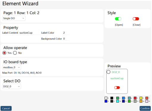
When the selected IO is True, the "On" icon under the control pattern is green. When the IO is False, the "Off" icon under the control pattern is red.
The single DO control provides button on/off interaction, and the "Allow Operation" attribute can be used to set whether a control can be operated on the "Operation/Display Panel". Click the button within the red frame in the "Operation/Display Panel" interface to operate the DO signal.
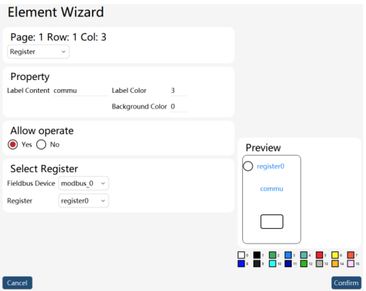
8.5.3.3 Register control
Register controls can monitor and modify the register values configured under "Communication" - "Registers". Registers can be filtered by "Bus device".
Attention: The register control does not support the register array type. The editing interface is shown below:
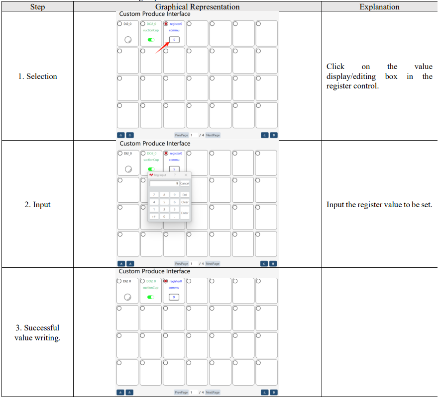
The register control does not provide a status-style display, but it can display the register value. The register control is edited by entering values using a numeric keyboard. On the "Operation/Display Panel" interface, you can click on the value "Display/Edit Box" for the value to enter the register value (attention: writing is only allowed when the register is set to "Write-only" mode).
Value writing steps:
8.5.3.4 Point position update control
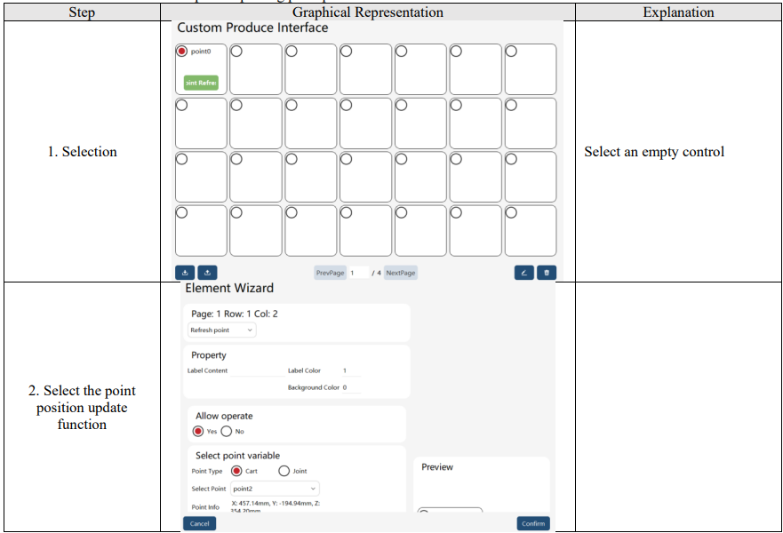
The point position update control can modify point information in the point list, with selectable point types including Cartesian and joint. The editing interface is shown below:

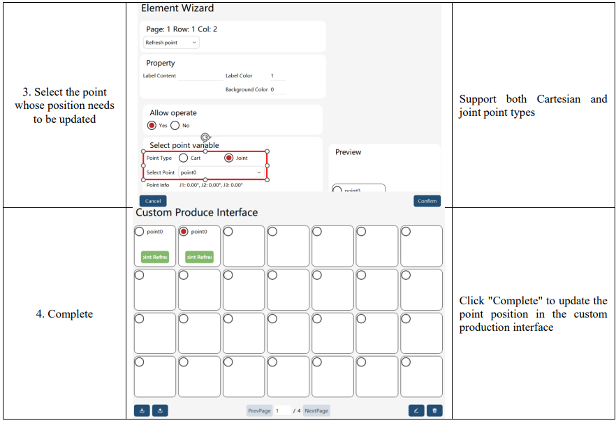
The point position update control does not provide status style display but offers an "Update Position" button.
Clicking the "Update Position" button on the "Operation/Display Panel" interface allows you to update the values of the selected point.
Steps for updating point position:
8.5.3.5 Project variable control
The project variable control can monitor and modify the variables configured under "Project" - "Variable List". The selectable variable types include int, byte, bool, and double. Variable array types are not supported.
The editing interface is shown below:
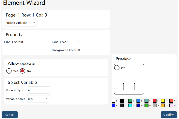
The project variable control does not provide a status-style display, but it can display the project variable values.
The project variable control is edited by entering values using a numeric keyboard. The "Allow Operation" attribute can be used to set whether the control can be operated on the "Operation/Display Panel".
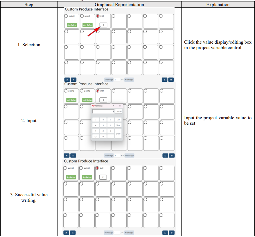
Click the value display/editing box on the "Operation/Display Panel" interface to write values to project variables.
Value writing steps:
8.6 Task list
The xCore control system supports multitasking.
Through multitasking, the "parallelism" of multiple robot programs can be realized. Typical application scenarios are shown below:
⚫ Monitor continuously one certain signal even if the Main program stops operating (it is similar to the background PLC function, but its response speed is much lower);
⚫ While the robot executes the main program of motion, it performs data reception, transmission, and other data processing with external devices, without being restricted by the execution logic of the main program;
⚫ Receive some inputs through the teach pendant while working;
The "Task List" in the xCore system provides a management interface for parallel processing tasks. Users can view the attributes of existing tasks, create new tasks, edit tasks, and delete tasks on this interface.
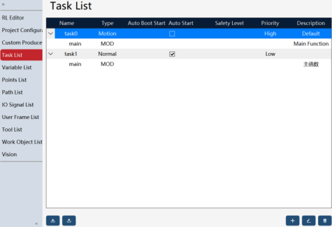
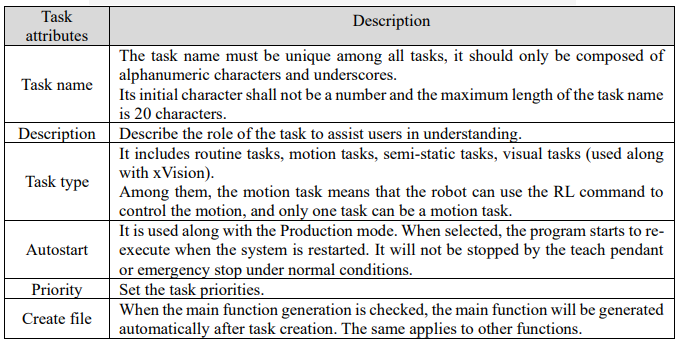
8.6.1 Task attributes
When creating or editing a task, it is necessary to set the task attributes.
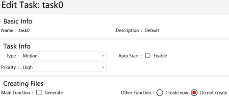
8.6.2 Regular tasks and motion tasks
8.6.2.1 New task
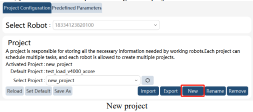
You need to create a new project before creating the first task. If you already have a project and want to add a new task, you don't need to repeat creating a new project.
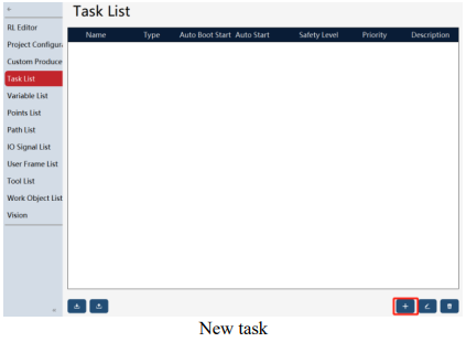
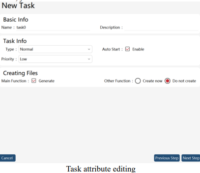
After creating a new task, you can edit the attributes of the task.
Note:
⚫ 10 tasks are supported.
⚫ There shall be one motion task at most.
⚫ Changes in the task type, task entry function, and whether it is a motion task attribute take effect immediately.
8.6.2.2 New program module
Each task can include several program modules (mod files). As shown below, you can click the Edit button,
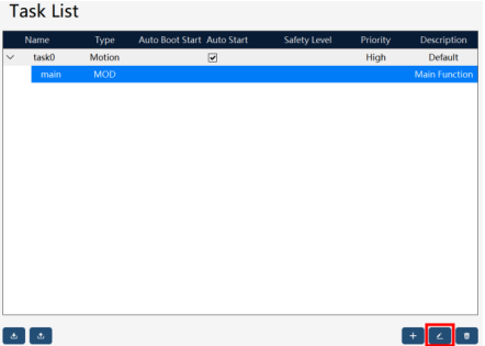
and click "+" on the new page to create a new program module. After entering the basic information such as the name and description of the module, you can click "OK" to complete the creation of the program module.
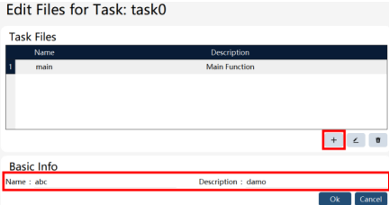
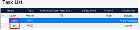
At this point, you can view the newly created program module in the task list.
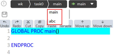
In the upper part of the RL editor, you can also select a new program module and program it
8.6.2.3 Starting and running
Click  in the upper part of the RL editor to select a task. Use the Start/Stop button or external signals to control the start/stop of the selected task in the condition of manual enabling or automatic power-on.
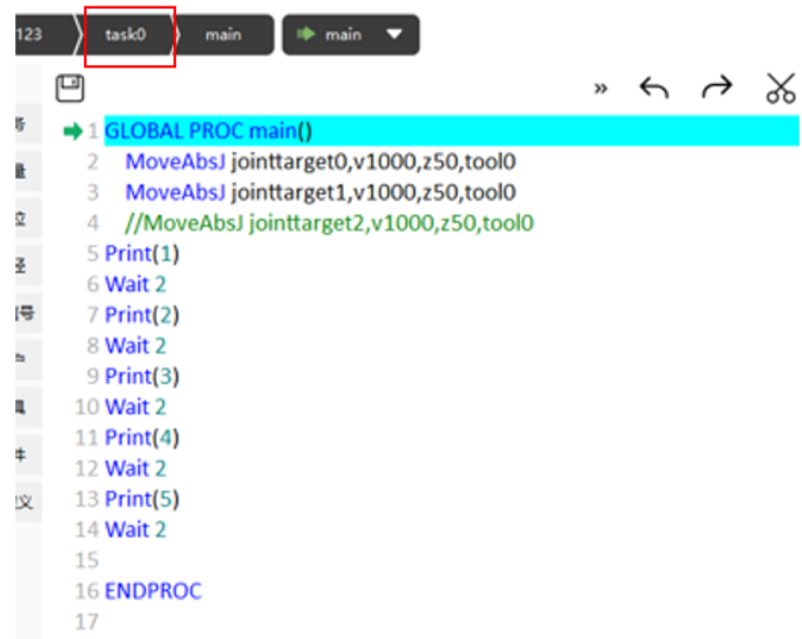
Use restrictions:
⚫ Generally, a background task will run cyclically. If a task does not contain any wait commands,
⚫ the background task may consume too much computing resources, causing the controller to be unable to handle other tasks;
⚫ The scopes of variable VARS and the constant CONST are limited to their respective tasks, but the GLOBAL-level PERS variable is a global variable;
⚫ When PPToMain is executing, all non-running tasks execute PPToMain;
⚫ When there are tasks running, it is forbidden to modify the contents in the Task List interface;
8.6.2.4 Inter-task communication
The inter-task communication supports two methods: PERS variable and interruption.
Inter-task communication by PERS variable
⚫ Global-level PERS variables with the same name shall be defined in all task projects that require communication, and the data type and dimension of variables shall be identical;
⚫ PERS variables shall be used to control task execution and data transmission where necessary;
⚫ All variables and tasks in the variable list and point list are available at will;
Use restrictions:
⚫ You just need to specify an initial value for the PERS variable in one of the tasks. If you have specified an initial value for the same PERS variable in multiple tasks, the initial value defined in the first running task will be used.
⚫ When a task waits for another task by means of the PERS variable and the WaitUntil or WHILE command, it is necessary to pay attention to coordinating with the wait command (greater than 0.1s) to avoid the program quickly executing the empty judgment command, and thus occupying too much system resources.
8.6.3 Semi-static task
Since v2.0.1, the xCore control system supports performing semi-static tasks. The semi-static task belongs to the multi-task function and runs a program written in RL language. Compared with regular and motion tasks, semi-static tasks have two features as follows: (1) After being properly configured, they can self-start after being switched on without any commands such as poweron and start-up commands; (2) The pause button is not effective on the semi-static task. With these two features, the operation cycle of a semi-static task covers almost the entire time from power-on to poweroff of the control system. Typical application of semi-static takes:
⚫ Judge the robot position periodically, and notify the host computer via registers, IOs, etc.;
⚫ Output custom heartbeat signal;
⚫ Transmit data among multiple devices;
8.6.3.1 Semi-static task creation
In the task list, click "+" to create a new task. Select Semi-static Task in the Type, complete other attribute settings, and click the "Next" button to create the semi-static task.
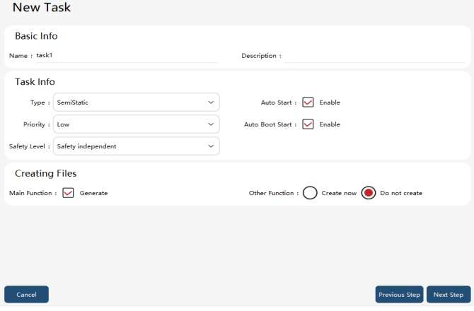
8.6.3.2 Starting and stopping of semi-static tasks
Just like the regular task startup, after creating and configuring a semi-static program, the semi-static task can be started by powering on in manual or automatic mode and clicking the “Start” button. If there is a semi-static task running in the project, there will be a prompt  in the middle of the bottom status bar. At this time, clicking pause or power off will not stop the semi-static task. Clicking the "semi-static status" button will pop up a confirmation dialog box
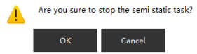 , and clicking "OK" will stop the semi-static task. When the semistatic task does not trigger a program exception, only this button can stop the semi-static task (the semistatic task can be paused only after the regular task is paused).
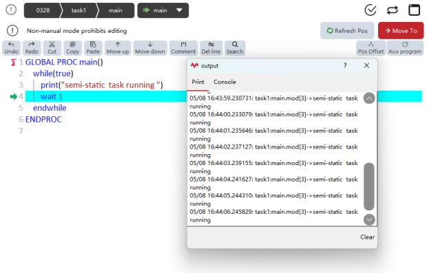
8.6.3.3 Configuring semi-static task for self-start
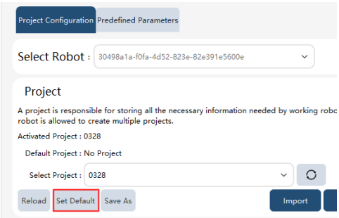
In the project configuration interface, set the project associated with the semi-static task as the default project.
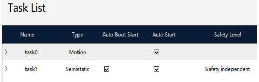
In the task list, check the two options, running on startup or not and running or not.
Finally, click pptomain to synchronize the project configuration from the HMI to the controller, allowing the semi-static task to self-start.
8.6.3.4 Safety level of semi-static tasks
In addition to configurations such as priority and "running or not" of regular tasks, the semi-static task has an additional feature: safety level.
It is used to define the controller's exception handling policy for the semi-static task as the semi-static task operates abnormally (e.g. data reception failed).
⚫ Safety irrelevant: It applies to the host computer or operators who do not care about the operating condition of semi-static tasks. A semi-static task configured with this safety level will be stopped individually if its operation is faulty, with the operation of other tasks not affected.
⚫ System stop: Applicable when the data of semi-static tasks affect the program's safety logic (e.g. deciding the motion point via a semi-static task, and informing the host computer how to control the robot via a semi-static task). The semi-static tasks of the System stop level will make all tasks paused if there is any fault in their operation.
8.6.3.5 Recommendations for semi-static task debugging
⚫ The controller supports single-step debugging of semi-static tasks in manual power-on mode.
However, it is still recommended to complete debugging with regular tasks first, and then change the task type to semi-static task to avoid unexpected startups of unfinished semi-static tasks during reboots in the debugging process;
⚫For semi-static tasks, it is recommended to add error handling for commands that may fail during execution. For example, ReadXX instructions may cause read timeout or failure due to various reasons such as network jitter or unexpected external device issues. To meet the requirement of keeping semi-static tasks running as much as possible, the try_catch statement shall be used to protect the code that may fail, and error handling shall be performed in the catch statement (such as using a goto statement to return to the Read operation and reread the data); and
⚫ Due to the specialty of long-term execution inherent to semi-static tasks, the single  and
and
cycle  run settings in the upper right corner of the program debugging interface do not apply to semi-static tasks. All semi-static tasks run in cycles.
8.6.4 Task monitoring
The current running status of each task can be monitored in the status monitoring.
8.7 List of variables
8.7.1 Variable naming rules
Variable names in the RL language can consist of letters, underscores, and numbers, but must start with a letter or underscore "_". However, variable names cannot be the same as system keywords. You can see Keywords pre-definition for RL system keywords.
In addition, there are precautions as follows:
In the same module, GLOBAL and LOCAL level variables with duplicated names are not allowed;
In different modules, GLOBAL variables with duplicated names are not allowed;
In different modules, LOCAL variables with duplicated names are allowed;
In the same module, no variables (GLOBAL, LOCAL, excluding ROUTINE) are allowed to have naming conflicts with functions in this module;
In different modules, no naming conflicts of GLOBAL level functions and variables are allowed;

8.7.2 Variable scope
The RL language system defines three scopes:
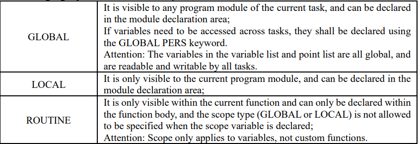
8.7.3 Storage type
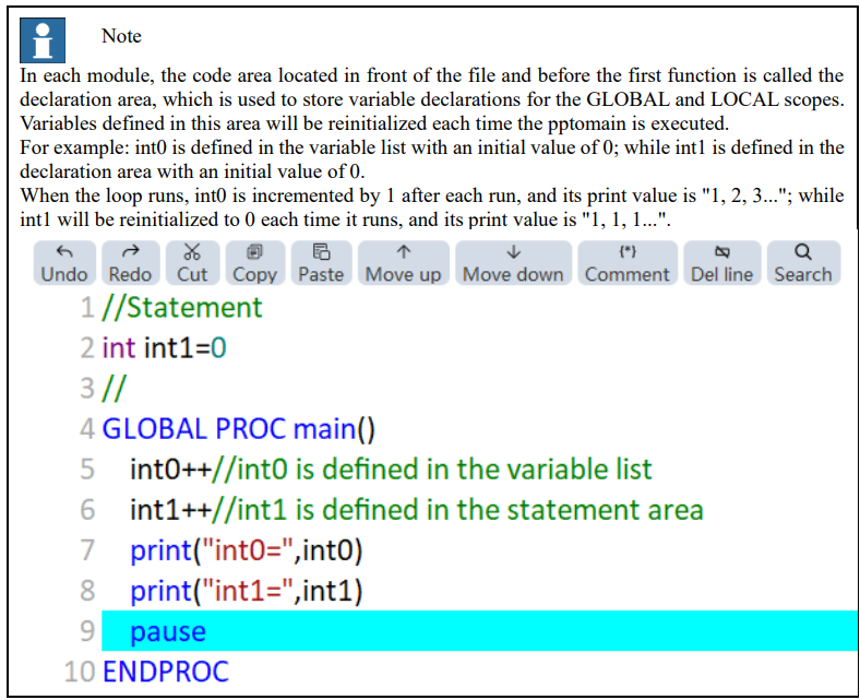
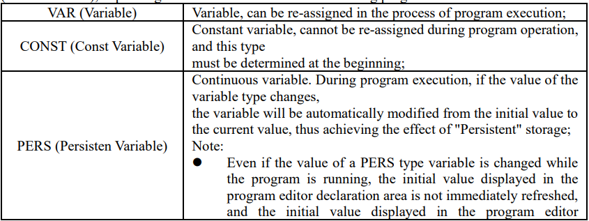
Each variable can be divided into three kinds: VAR (Variable), PERS (Persistent Variable), and CONST
(Const Variable), depending on whether it can be modified during program execution.

8.7.4 Keywords pre-definition
The following are reserved keywords (case insensitive) that are predefined for the RL language:
Module, EndModule, Proc, EndProc, Func, EndFunc, SetDO, DO_ALL, SetGO, SetAO, WaitDI, Wait,
WaitUntil, WaitWObj, WBID, Q, P, J, V, W, T, S, L, CA, DURA, IGNORELEFT, EJ, 1J, FCBV, FCCV,
FCOL, FCXYZ, FCCART, PE, PER, TCP, ORI, EXJ, CFG, PDIS, JDIS, MoveAbsJ, MoveJ, MoveL,
MoveC, MoveT, LOCAL, TASK, GLOBAL, VAR, CONST, PERS, INV, DOT, CROSS, sin, cos, tan,
asin, cot, acos, atan, atan2, sinh, cosh, tanh, ln, log10, pow, exp, sqrt, ceil, floor, abs, rand, GetCurPos,
Print, PrintToFile, ClkRead, TestAndSet, IF , Else, Endif, WHILE, ENDWHILE, for, from, to, endfor,
Break, Continue, Del, Int, Double, Bool, String, BYTE, Robtarget, Speed, Zone, Tool, Wobj, Jointtarget,
TriggData, Load, FCBoxVol, FCSphereVol, FCCylinderVol, FCXyzNum, FCCartNum, Pose, CLOCK,
INTNUM, SYNCIDENT, TASKS, Call, Return, EXIT, Pause, StopMove, StartMove, StorePath,
RestoPath, True, False, Interrupt, When, Offs, CalcJointT, CalcRobT, CRobT, RelTool, SocketCreate,
SocketClose, SocketSendByte, SocketSendInt, SocketSendString, SocketReadString, SocketReadBit,
SocketReadInt, SocketReadDouble, AccSet, MotionSup, TriggIO, TriggJ, TriggL, TriggC, On, Off,
clock, intnum, userframe, pinf, ninf, FCFRAME_WORLD, FCFRAME_TOOL, FCFRAME_WOBJ,
FCFRAME_PATH, FCPLANE_XY, FCPLANE_XZ, FCPLANE_YZ, FC_LINE_X, FC_LINE_Y,
FC_LINE_Z, FC_ROT_X, FC_ROT_Y, FC_ROT_Z, Offs, CalcJoinT, CalcRobT, CRobT, RelTool,
Start, Time, ClkReset, ClkStart, ClkStop, CONNECT, WITH, IDisable, IEnable, ISignalDI, Single,
SingleSafe, WaitWobj, DropWobj, WobjIdentifier, WobjAngle, ActUnit, DeactUnit, INTNO, Exp,
DoubleToStr, WaitSyncTask, FCAct, FCDeact, FCLoadID, FCCalib, FCSupvForce, FCSupvTorque,
FCSupvPosBox, FCSupvPosSphere, FCSupvPosCylinder, FCSupvOrient, FCSupvOrient,
FCSupvReoriSpeed, FCSupvTCPSpeed, FCCondForce, FCCondTorque, FCCondOrient,
FCCondReoriSpeed, FCCondPosBox, FCCondPosCylinder, FCCondPosSphere, FCCondTCPSpeed,
FCCondWaitWhile, FCRefLine, FCRefRot, FCRefSpiral, FCRefCircle, FCRefForce, FCRefTorque,
FCRefStart, FCRefStop, FCSetSDPara
8.7.5 Number system conversion
The RL language supports direct entry of hexadecimal, binary, or values of scientific notation by adding a number system identifier after a number or letter.
Example 1
After the "h" suffix is added after 0−9, a−f, or A−F, the RL compiler treats the corresponding number or letter as hexadecimal and converts it to decimal in the compiler. For example: 8h stands for 8 in hexadecimal and 8 in decimal; bh stands for b in hexadecimal and 11 in decimal; 25h stands for 25 in hexadecimal and 37 in decimal;
Example 2
After the "b" suffix is added after 0−9, a−f, and A−F, the RL compiler treats the corresponding number or letter as binary. For example: 1b stands for 1 in binary and 1 in decimal;
10b stands for 10 in binary and 2 in decimal; 1010b stands for 1010 in binary and 10 in decimal;
Example 3
Adding the "e±x" after a number indicates that the number is multiplied by 10 to the x power. For
example:
5e+20 represents 5×10^20;
26e−15 represents 26×10^(−15);
112e−10 represents 112×10^(−10);
8.7.6 Variable declaration
A declaration must be made before using a variable. The format of the variable declaration command is as follows:
SCOPE STORAGE TYPE varname [= value]
Where:
1. SCOPE refers to variable scope. Please refer to Variable Scope;
2. STORAGE refers to variable storage type. Please refer to Storage Types;
3. TYPE refers to variable type, and can be a basic type or a special type. Please refer to Variable
Type;
4. varname is the variable name. Please refer to Variable Naming Rules; The content in square bracket [ ] is optional and can be either initialized or not when variables are declared. For variables that are not explicitly initialized when they are declared, the system automatically assigns different initial values as per the type of the variables. The default initial value may cause program execution problems in some cases, so it is recommended to initialize each manually added variable.
Example
There are a few examples of variable declarations as follows:
Example 1
VAR int counter = 8 //Declare the integer variable count and assign an initial value of 8
VAR double time = 2.5 //Declare floating-point variable time and assign an initial value of 2.5
VAR bool ifOpen = true //Declare the variable bool type ifOpen and assign the initial value of true
Example 2
In general, no duplicate names are allowed for variables:
VAR int counter = 8
VAR double counter = 2.5
The compiler will report an error message at this time by prompting "Failed to add variable".
Example 3
However, a global variable and a local variable can have the same variable name:
VAR int counter = 1
GLOBAL int counter = 555
Although variables with different scopes allow duplicate names, it is not recommended to use variables with duplicate names in order to avoid confusion and misuse, unless the variables with duplicate names have special technological advantages.

Use restrictions
The ROUTINE variable that declares the PERS storage type is not supported; When there is a duplicate name for variables or functions of different levels, the compiler will decide which variable to be used based on the priority of the scope. Variables with the highest priority order will be selected first, and those with lower priority order will be obscured and hidden. The priority of scopes is as follows:
⚫ When the variable names are duplicated, the priority of scopes is as follows: ROUTINE> LOCAL> GLOBAL;
⚫ When the function names are duplicated, the priority of scopes is as follows: LOCAL > GLOBAL;
8.7.7 User variable hold
The user variable "a" with hold is created in an RL project. This user variable is marked as a PERS variable, then the value of this variable is held on the non-volatile storage media when RL stops, the robot restarts, shuts down, or is powered off. When the robot is powered on again or RL is running again, the value of variable a is restored to the value held. The initial value is assigned only when the variable is created for the first time or re-edited. (Attention: Only PERS variables added to the variable list possess the hold attribute. However, PERS variables defined in the variable declaration area have no hold attribute.)
The persistence is supported for the following user variable types: Int, byte, double, bool, string, pose, speed, zone, fcboxvol, Fcspherevol, fccylindervol, fcxyznum, fccartnum, torqueinfo, socketserver,
socketconn, and serials.
User variable hold configuration
On the RL project interface, the entries where persistent variables can be created as shown in the red boxes below:
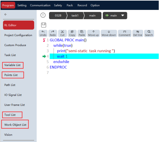
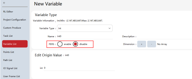
Click the variable list, point list, tool list, or work object list to create user variables of corresponding type. All variables for which the persistent attribute can be created have a "persistent" attribute item, where "yes" indicates that the variable is a persistent variable, marked as a PERS variable. For example, create a PERS variable of int type, whose configuration is as follows: (Other types can be configured by analogy)
Modification of PERS variable
The PERS variables of the xCore control system are stored in the form of initial value+hold value. The initial value refers to the data input by users to the variable list, and the hold value is the data, after it is modified by the program, stored on the non-volatile storage medium. The hold values of base types (int\bool\double) can be observed by status monitoring, and structure data (e.g., points, tools, work objects) can be printed by the print command.
During the operation of RL program, the PERS variable can be modified by the operator "=", and the modified data will be stored as a hold value within the controller. For the next time of program operation, the hold value of corresponding variable is preferred to be read, and if there is no hold value, the initial value of the variable is read.
If the PERS variable is modified by the point update button or the editing function of the variable list,
the initial value and hold value are modified at the same time.
8.7.8 Variable list operation
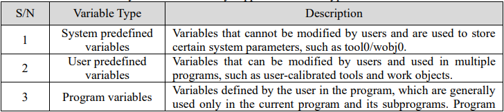
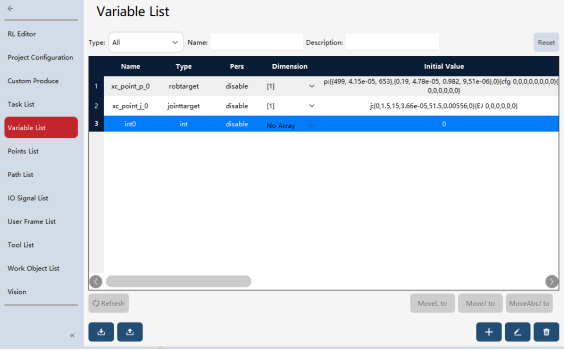
The variable management interface allows the creating, viewing, modification, and deletion of almost all variables in the robot system. The currently supported variable types include:

8.7.8.1 Variable viewing
For some types of variables that have specifically defined steps, such as: speed/zone (defined and modified on the auxiliary programming interface). Although such variables can be viewed and modified in the Variable View interface, it is still recommended to use the dedicated interface for modification for the sake of convenient operation and fewer errors. The variable management interface should be used primarily for viewing operations

8.7.8.2 Variable editing
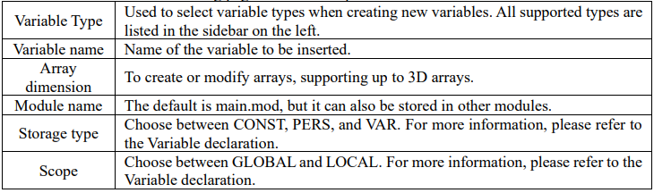
If you need to add variables or modify certain existing variables, you can click the "New" or "Modify" button to enter the variable editing page for relevant operation.
8.8 Point list
8.8.1 Overview
The point list is used to manage the robot points involved in projects in a unified manner. The points used in the RL program need to be configured in the point list before they can be used in the program.
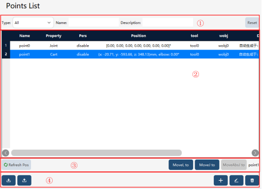
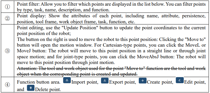
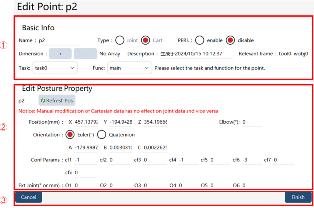
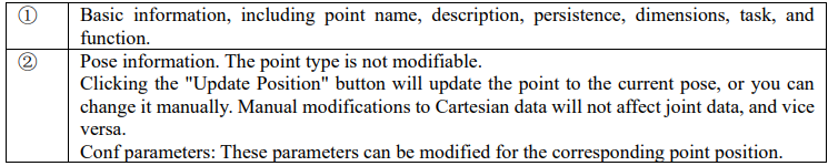
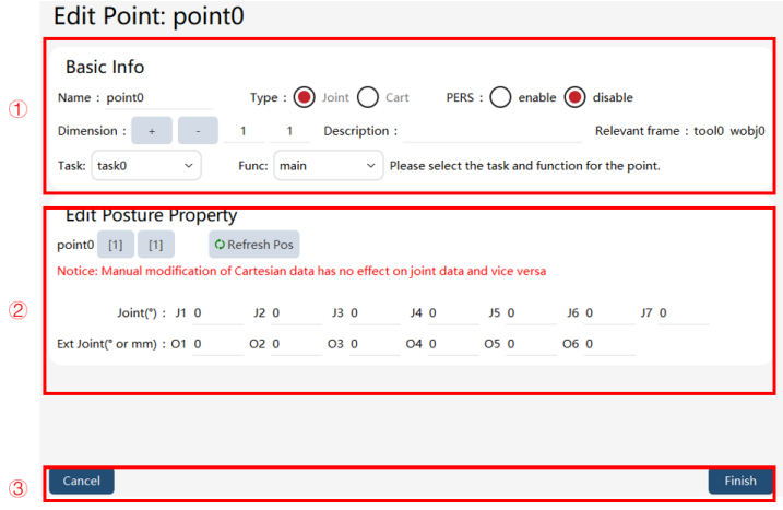
Point editing page:
Cartesian space point:

Joint space point:

8.8.2 Operation examples
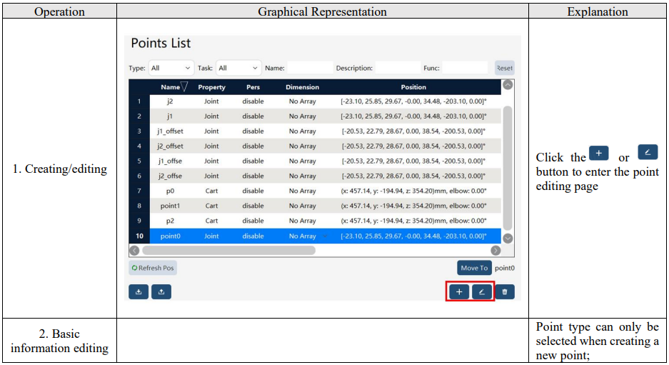
8.8.2.1 Point creation/editing
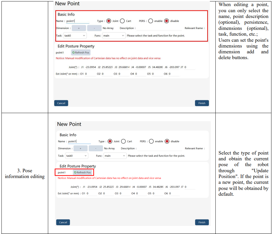
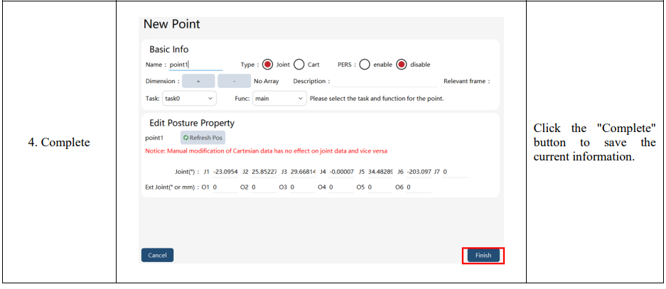
8.8.2.2 Point "Move to"
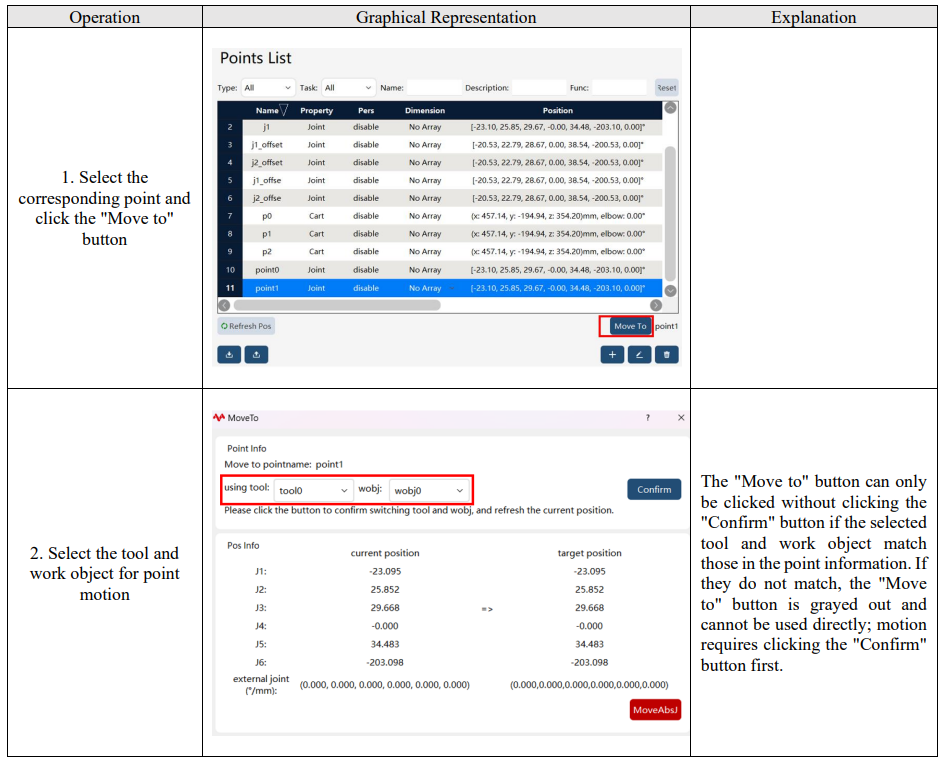
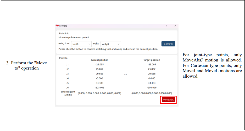
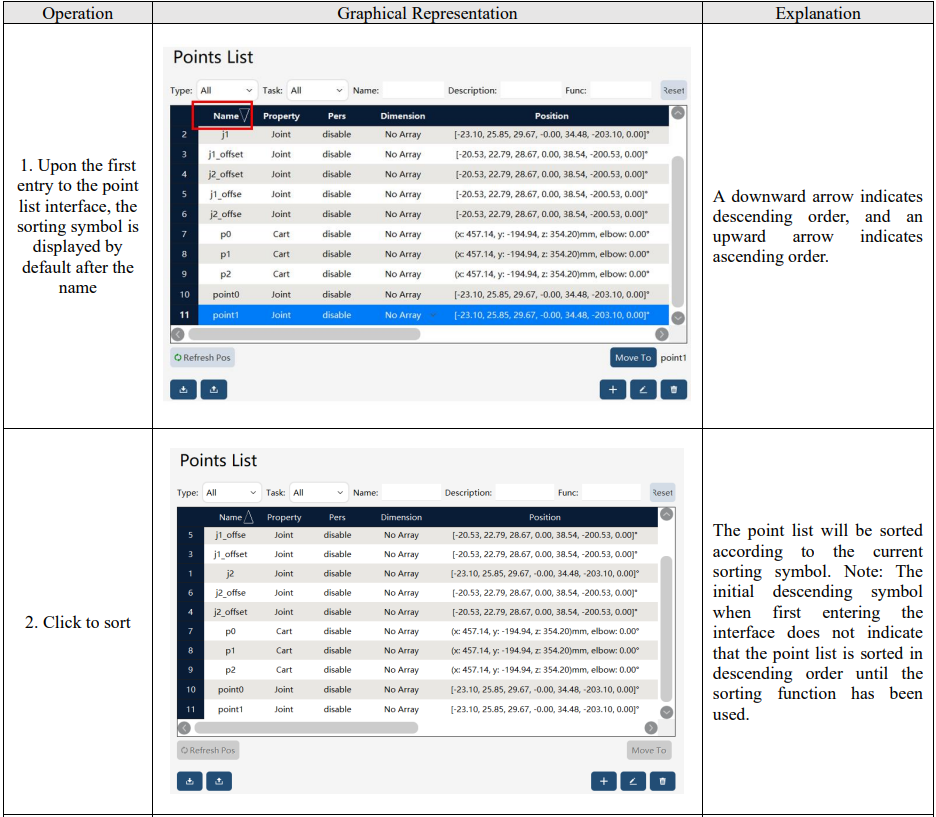
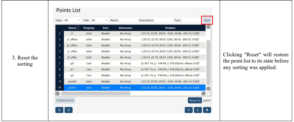
8.8.2.3 Point sorting
8.9 Path list
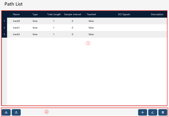
8.9.1 Overview
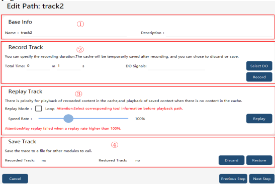
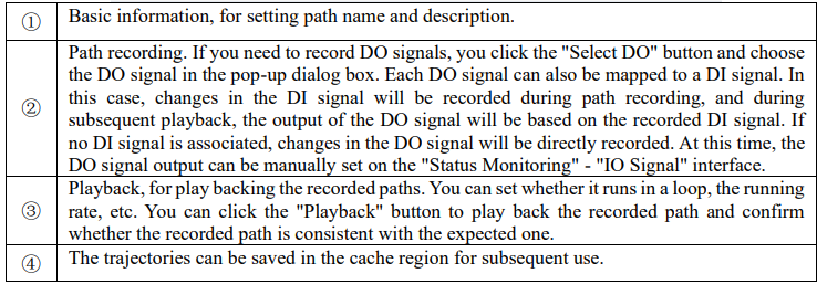
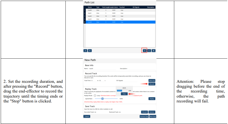
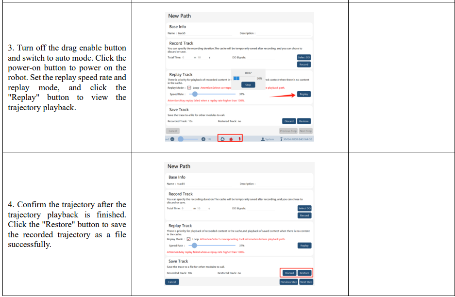
The path list is used to record the trajectories of the drag teaching and perform operations such as trajectory playback.

Path editing page:
8.9.2 Operation examples

8.10 IO signal list
8.10.1 Overview
In addition to the default Universal IO signals created by the "IO device" in the enabled state, if you want to use the IO device alone to create a user IO signal, you need to create it on the "IO Signal List" page.
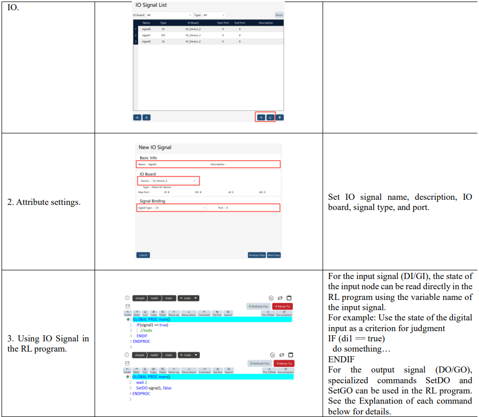
The signalxx type variables are used to store and access IO signals in the RL program. For details, refer to relevant sections about RL commands.
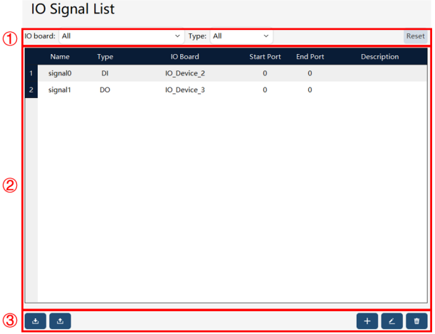
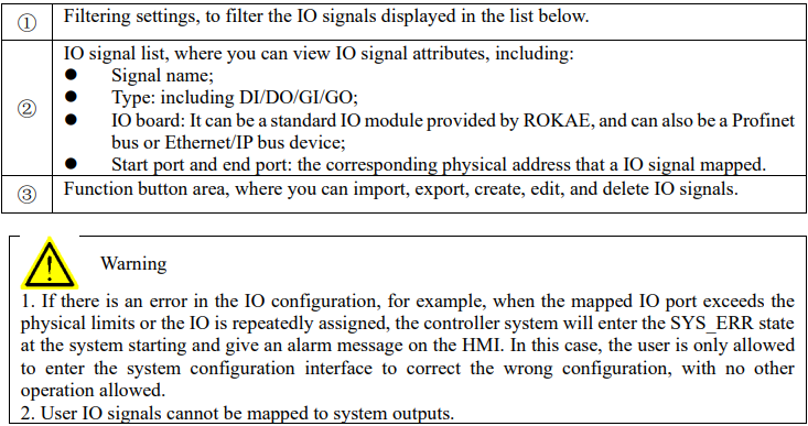
The configured IO can be viewed on the status monitoring interface, on which the forced output or simulation input of the IO is supported.
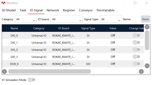
8.10.2 Operation examples

8.11 User frame list
8.11.1 Overview
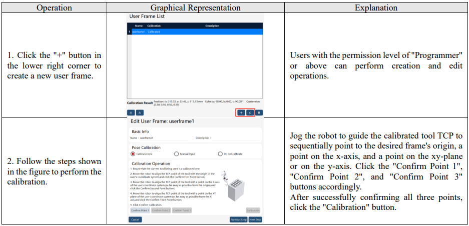
The user frame is used as a reference frame when defining the work object frame, and it cannot be used separately
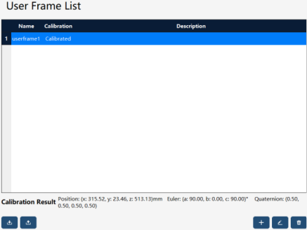
When establishing a user frame, you can choose "Calibration now", "Manual input" or "Do not
calibrate". When "Calibration now" is selected, the 3-point method is used to calibrate. Before calibrating the user frame, the user needs to first calibrate a tool and then use the TCP of the tool to calibrate the user frame. For this, it is recommended to use a tool with tips. "Manual input" is allowed if the user frame is known in advance. Another option is "Do not calibrate", in which case the user frame is considered as the world frame by default.
8.11.2 Operation examples
8.12 Tool list
8.12.1 Overview
A tool is a device that is installed on the flange of a robot to complete a specific processing procedure. Common tools include pneumatic/electric grippers, welding guns, and sprinklers. No tool is attached to the robot when it is delivered from the factory, and you need to purchase or design appropriate tools according to the actual situation and complete the installation and settings in order to make the robot work. Any tool shall be calibrated to get the Tool center point data before it is used. In the xCore controller system, the data type corresponding to tools is "tool". For detailed explanations of the "tool", please refer to the section "RL Commands-Variables".
8.12.2 Basic concept
Tool attributes include: center point and orientation, which represent the geometric parameters of the tool; and weight, center of mass and rotational inertia, which represent the dynamic parameters of the tool.

8.12.2.1 Tool center point
Tool Center Point (TCP) is a specific point on the tool that is normally used by the robot to carry out processing work, such as the wire tip of a welding gun and a tip of a pneumatic gripper. The robot can rotate around the TCP and change its orientation while keeping the position of the TCP unchanged.
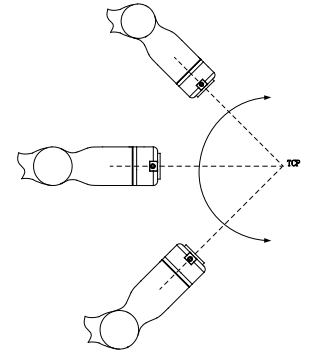
Different tools may have different TCP, and determining an appropriate TCP according to actual conditions can significantly increase programming efficiency.

8.12.2.2 Tool frame
The calibration of tool frame refers to the process of determining the pose of the tool frame relative to the flange frame.
If the pose information of the tool relative to the flange is known, you can select "manual input" on the teach pendant and input it directly without performing the calibration process.
If the pose information of the tool relative to the flange is unknown, xCore provides three methods for tool frame calibration:
⚫ Four-point method, used to calibrate the center point of the tool frame.
⚫ Three-point method, used to calibrate the orientation of the tool frame.
⚫ Six-point method, used to calibrate the center point and orientation of the tool frame at the same time, which is equivalent to the integration of the four-point method and the three-point method.
Additionally, xCore provides the "TCP correction function" to further improve the position accuracy after tool frame calibration.
8.12.2.3 Load parameters
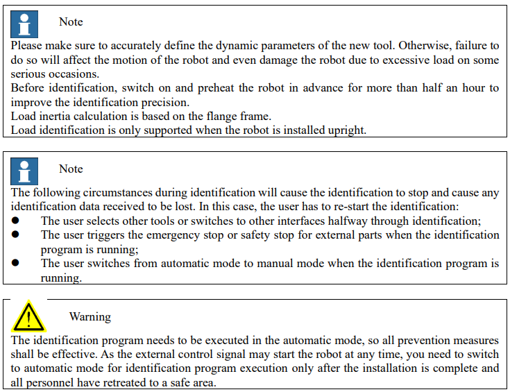
The xCore system utilizes load-type variables to store the load parameters of tools. Attention: When external tools are used, the load parameters in the tool variables store the load of the handheld work object. There are two ways to define a tool's load parameters: If the user knows the tool load data, the user can select the manual input method on the tool frame calibration interface and input the corresponding data directly; If the tool load data are unknown, they can be obtained using the load identification function of the xCore system.
8.12.2.4 Load identification
The load identification function can conveniently calculate the dynamic parameters of the tool.
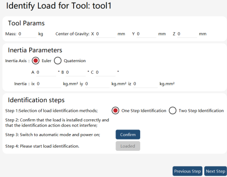
Two methods are supported for load identification: one-step identification and two-step identification. Industrial robots only support two-step identification, and the precision of two-step identification is usually superior to that of one-step identification. "Two-step identification" operation procedure:
1. Switch the robot to the automatic mode and power on;
2. Run the empty load identification program in the no-load state and wait for the program to complete;
3. Mount the tool load, run the load identification program, and wait for the program to complete;
4. When the identification is completed, the identification result window pops up, and you click "Save" to save.
Collaborative robots support "one-step identification", whose operation procedure is as follows:
1. Select the one-step identification method for load identification;
2. Install the load and ensure that it is properly mounted and that there is no interference during the identification process;
3. Switch to automatic mode and power on;
4. Click the "Loaded button", run the identification program, and wait for the program to complete;
5. Confirm the identification results and save them.
8.12.2.5 TCP correction
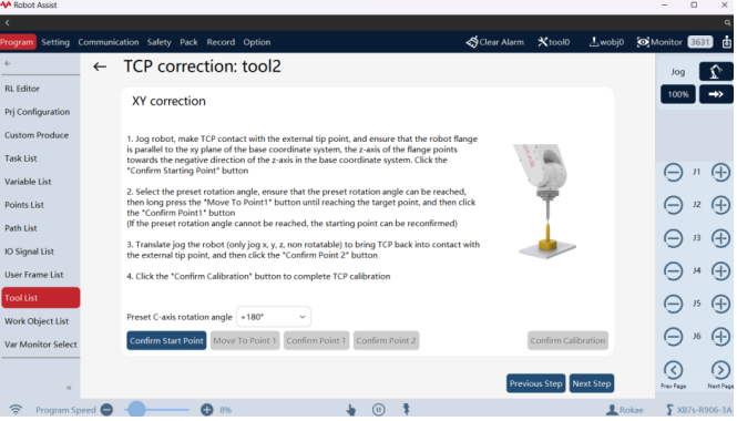
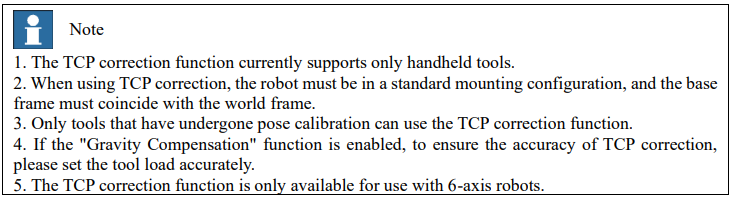
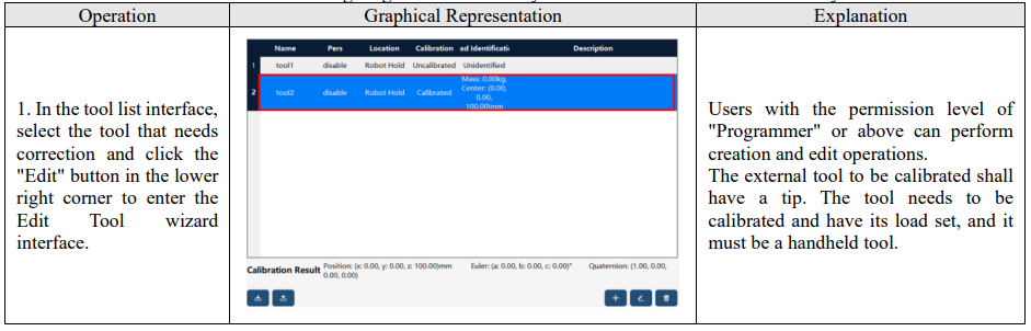
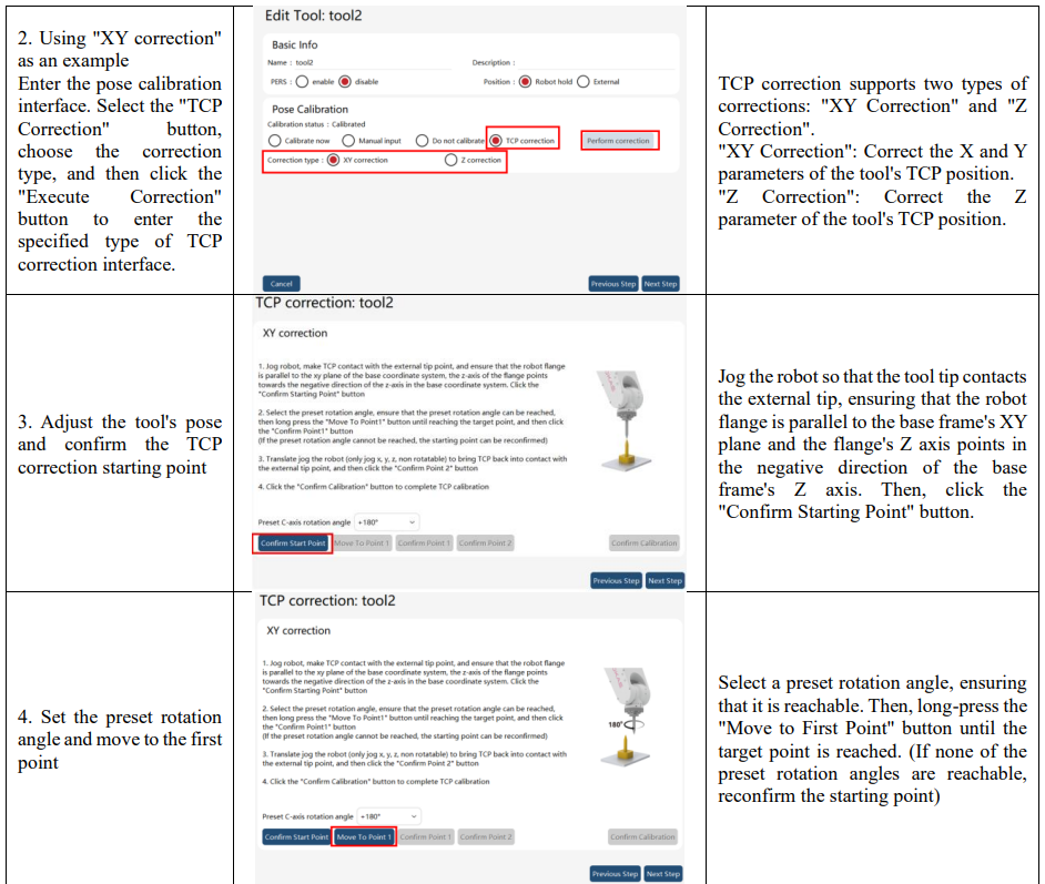
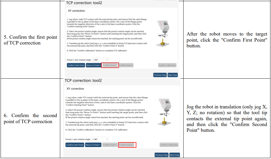
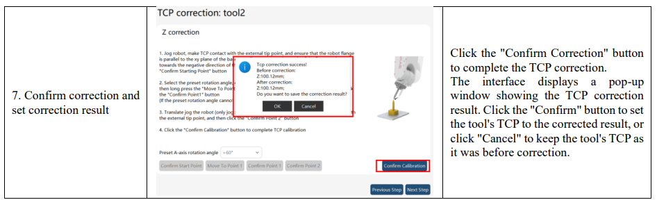
xCore provides the TCP correction function to correct the Tool Center Point (TCP) of the tool frame. For handheld tools that have undergone pose calibration, use the TCP correction function to improve the accuracy of the TCP position. In cases where deformation of the tool's end effector or errors in the tool installation position cause significant deviations between the theoretical TCP and the actual TCP, the TCP correction function can be used to correct and quickly recalibrate the TCP of the tool frame. The TCP correction function currently supports two types of correction: XY correction and Z correction, which are used to correct the X, Y, and Z position parameters of the tool frame's TCP.
8.12.2.6 Use of tool frame
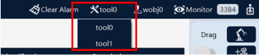
Used during Jog:
If it is necessary to use a special tool for Jog operation, select the desired tool in the drop-down list of the 'Tool' in the menu on the upper side of the teach pendant interface
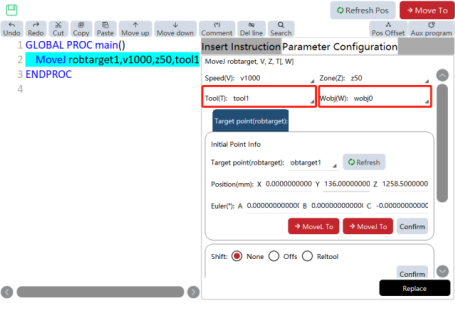
Used in the RL program:
It is very simple to use a special tool in the program, and you just need to use the desired tool in the "Tool" parameter of the motion statement. When the "Aux Program" interface of the teach pendant is used to write motion commands, the default "Tool" and "Wobj" are tool0 and wobj0.
8.12.2.7 External tools and handheld tools
In most cases, a tool is installed on the robot, and the tool moves with the robot to complete specified work. Such a tool is called handheld tool. Typical handheld tools include: grippers, suction cups, and welding guns.
In certain specific situations, installing a tool onto the robot may affect its normal usage, such as during grinding or gluing. In these cases, it would be more appropriate to mount the work object on the robot and fix the tool at a specific external location. We call these tools that are installed outside the robot and fixed at a certain location external tools (some brands call them Stationary Tool or Remote TCP), and the corresponding work objects are called handheld work objects.
8.12.3 Operation examples
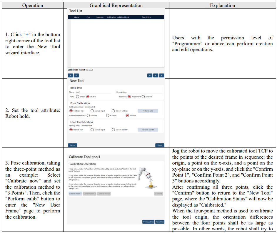
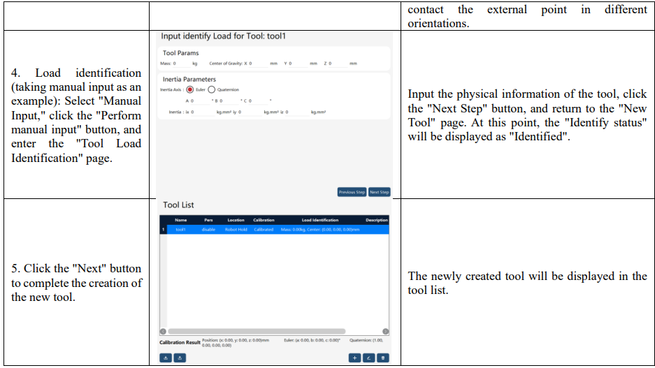
8.12.3.1 New handheld tool
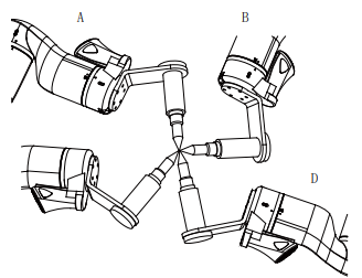
Before the calibration of tool frame, the user needs to prepare a fixed external point, which shall be located within the robot’s working range and can be contacted by the calibrated tool in a very flexible orientation.
8.12.3.2 New external tool
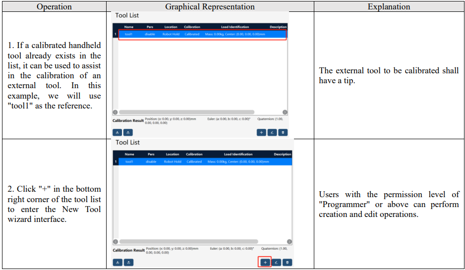
The calibration methods for external tools are consistent with those for handheld tools, supporting three methods: six-point method, four-point method, and three-point method.
Attention: To calibrate the external tool frame, it is necessary to use the already calibrated handheld tool.
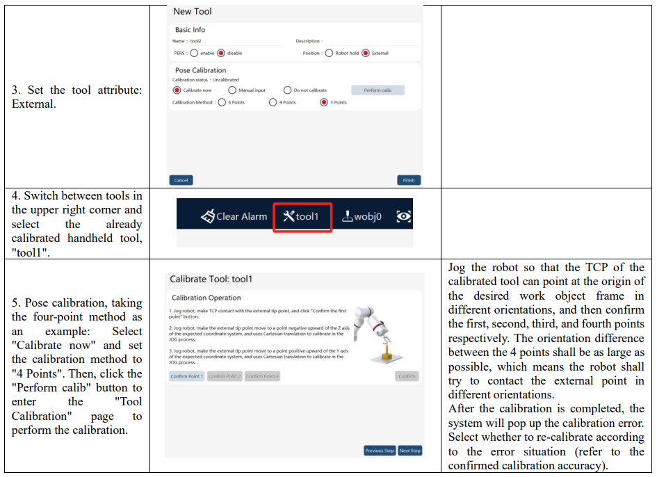
Note:
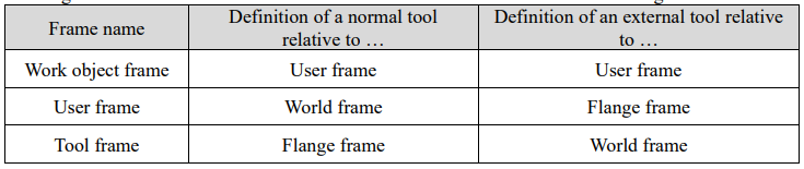
The external tool must be used together with the corresponding work object, meaning among the Position parameters which are selected at the same time in the tool and work object respectively, one must be External while the other be Robot hold. Otherwise, the system will prompt an error and forbid jogging the robot. The reference frames for defining tool frames and work frames of external tools differ from those for defining tool frames and work frames of normal tools. You can refer to the following table
8.12.3.3 Use of TCP correction
Before using the TCP correction function, prepare a fixed external tip point that must be within the robot's working range and accessible by the tool to be calibrated in a relatively flexible orientation.
8.13 Work object list
8.13.1 Overview
Work object refers to the object that is processed or handled by a robot with a tool. The xCore system uses wobj (Work Object) type variables to describe an actual work object. Defining a work object means creating a wobj variable. The motion trajectories of robots are defined within the work object frame for two good reasons:
(1) When the work object moves or multiple identical work objects are being processed, the user only needs to recalibrate the work object frame, and all the paths in the program can be updated accordingly without the need to rewrite all paths in the program;
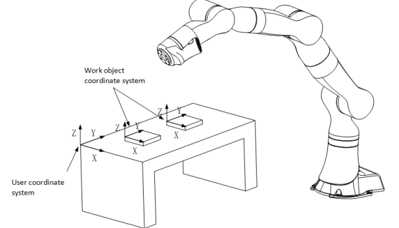
(2) It allows the processing of the work objects that are moved by an external axis (such as track and positioner); Each work object is jointly defined by two frames: one is user frame, which can be understood as the workbench/table where the work object is placed and is particularly useful when multiple identical work objects are handled; and the other is work object frame, which can be interpreted as the work object itself on the workbench. The path points of the robot are described based on the tool position relative to the work object position.
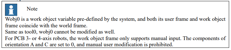
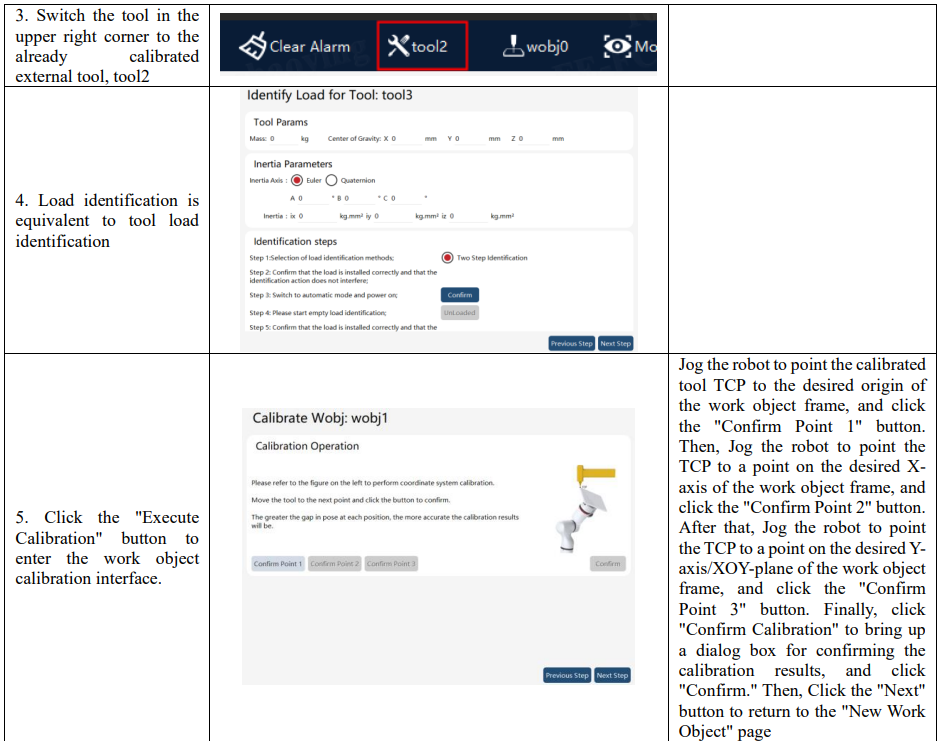
For using the external tool function, the corresponding work object shall be installed on the robot. In this case, the work object is called handheld work object. The handheld work object also needs the calibration of the work object frame and must use the calibrated external tool for calibration. For more details, please refer to the external tool function.
8.13.2 Use of work object frame
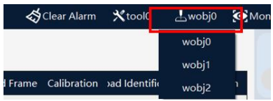
Used during Jog:
If it is necessary to perform Jog operation in a special work object frame, select the desired work object in the drop-down list in the menu on the upper side of the teach pendant interface.
Used in the RL program:
It is very simple to use a special work object in the program, and you just need to use the desired work object in the "Wobj" parameter of the motion statement. When programming the motion commands on the "Aux Program" interface of the teach pendant, the "Tool" and "Wobj" in default are consistent with those used during Jog operation, which are the currently selected "Tool" and "Wobj" in the menu on the upper side of the interface are currently selected. For the detailed operation steps, please refer to Insert Command.

8.13.3 Operation examples
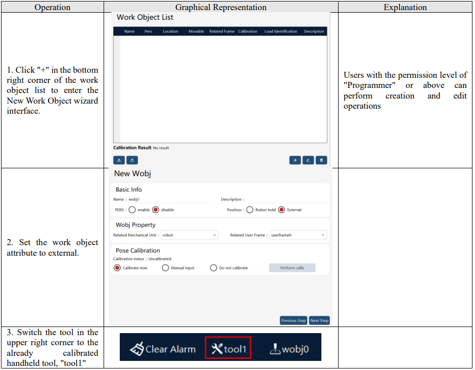
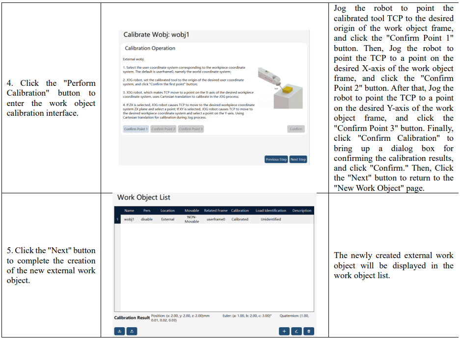
8.13.3.1 New external work object
To calibrate the external work object frame, it is necessary to use the already calibrated handheld tool for assistance.
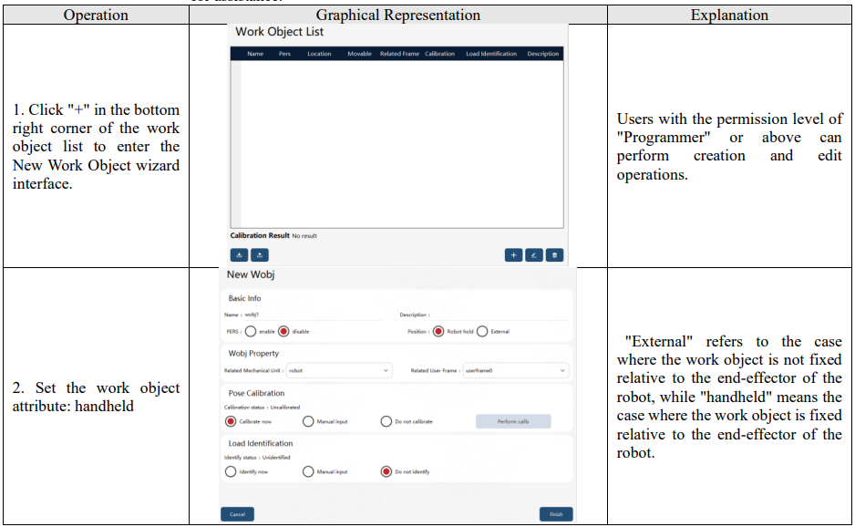
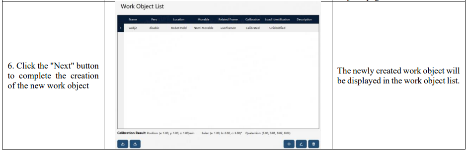
8.13.3.2 New handheld work object
To calibrate the handheld work object frame, it is necessary to use the already calibrated external tool for assistance.
8.14 Variable monitoring selection interface
8.14.1 Overview
The variable monitoring selection interface is used to add variables that need to be monitored.