9. Setting
9.1 Introduction to this chapter
This chapter provides a detailed introduction to various settings of the xCore control system.
9.2 Controller settings
9.2.1 Basic settings
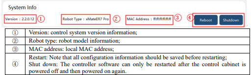
9.2.1.1 System information
9.2.1.2 System configuration
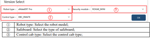
Note: Please do not modify the system configuration. In special circumstances, adjustments should be made under the guidance of the manufacturer.
9.2.1.3 System time
The system time provides a time reference for functions such as log.
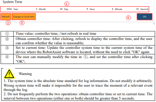
9.2.1.4 System IP properties
Configure the connection mode, IP, and subnet mask of the robot's external network port on this page.
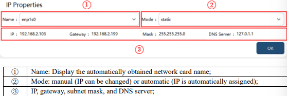
Note: The IP address of the debugging network port can only be modified to 192.168.0.160 or
169.254.160.160. When the IP of the debugging network port is 192.168.0.160, the IP of other network
ports cannot be modified to the 192.168.0 network segment; when the IP of the debugging network port is 169.254.160.160, the IP of other network ports can be modified to the 192.168.0 network segment but not to 192.168.0.160.
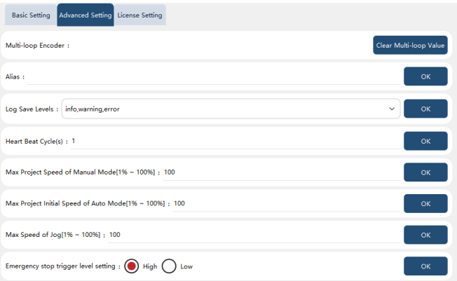
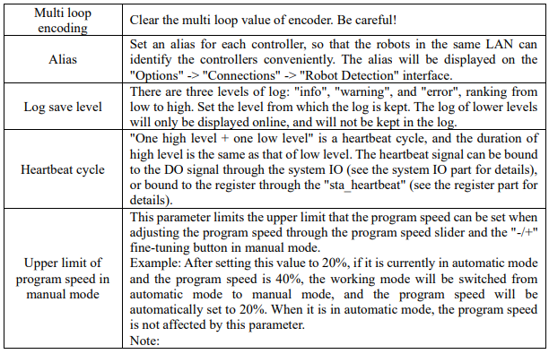
9.2.2 Advanced settings
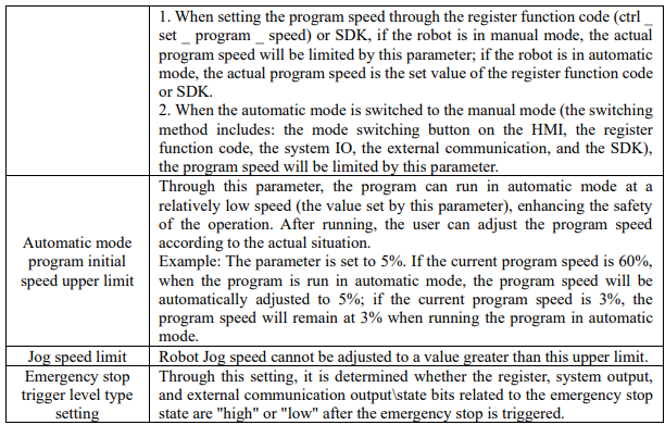
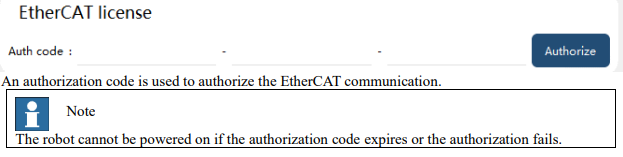
9.2.3.2 Function authorization
The xCore system supports some optional software functions, which are divided into two types:
1. Languages: Japanese, Korean, Russian, and English;
2. Process packages: PV inserting process package, PV typesetting process package, laser welding process package, and SDK secondary development interface;
To enable optional functions, you can purchase an authorization code file based on the list of function to be enabled.
Note: The authorization information is bound to the controller of the robot, one robot, one file.
Activation method: In "Settings"−"Controller settings"−"Authorization settings"−"Function authorization", click "Select file", and select authorization file for authorization. If the authorization is successful, restart RobotAssist according to the prompts to enable the optional functions. Authorization validity: At present, the function authorization is permanently valid, and the controller version upgrade, configuration deletion, factory reset, etc. do not affect the authorization state. Authorized functions: The functions that the current robot has authorized are displayed.

Associated content: In "HMI Settings"−"Basic Settings"−"Language", only authorized languages are displayed.
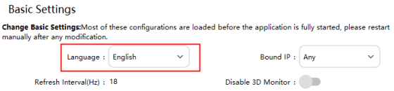
9.3 HMI settings
9.3.1 Basic settings

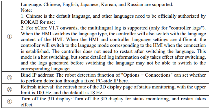
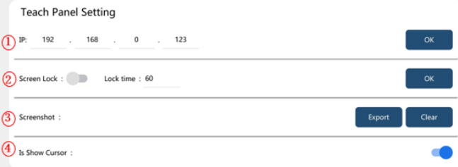

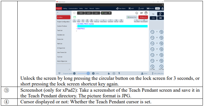
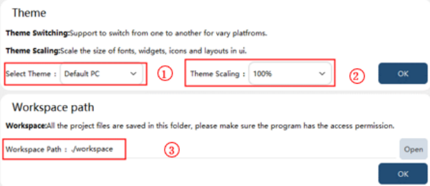

9.3.2 Teach Pendant mode
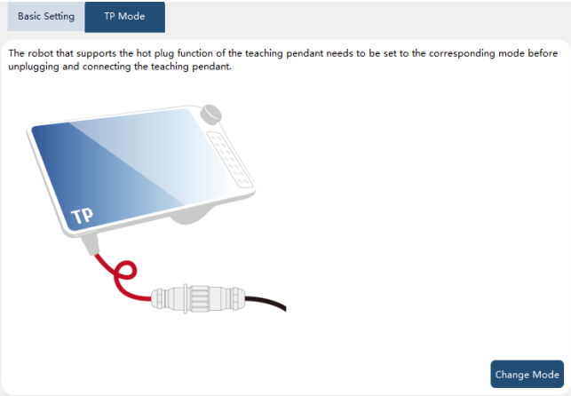
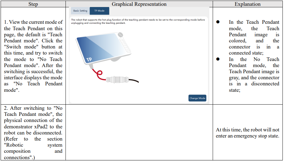
When the robot is turned on and used, it may be necessary to disconnect the physical connection between the xPad2 Teach Pendant and the robot. If the physical connection is directly disconnected, the robot will enter an emergency stop state. If you want not to affect the normal operation of the robot, you can follow the following steps
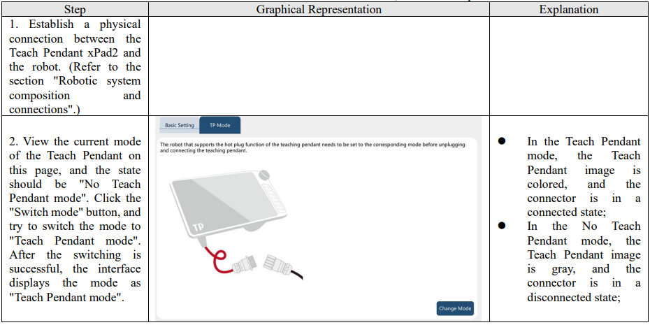
To reconnect the Teach Pendant xPad2 to the robot, follow the steps below:
9.4 User group
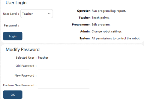
The xCore system is equipped with five levels of built-in users, which are Operator, Teacher, Programmer, Admin, and System based on their operating permissions. After connecting to the controller, it defaults to logging in with operator permission. When switching to other permissions, a password needs to be entered.

Note:
⚫ A user of a higher permission level can modify the password of a same- or lower-level user.
⚫ Operator-level user passwords cannot be modified.
⚫ Switching from a high-level user to a low-level user does not require entering a password.
Please refer to the appendix for details of the permissions of each user group.
9.5 Calibration
The xCore system provides robot calibration functions, including mechanical zero calibration, soft calibration (industrial robot), force sensor zero calibration (collaborative robot), and base frame calibration. The calibration function can perform one-key calibration or single-axis calibration.
9.5.1 Zero calibration
The zero calibration here refers to the mechanical zero calibration, which aims to make the theoretical zero of the robot coincide with the actual mechanical zero.
The zero scale is preset on the robot body, and the joints are aligned, that is, after returning to the mechanical zero, the calibration can be performed.
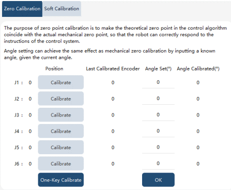
To prevent users from losing the zero due to accidental operation during zero calibration, after clicking the "Calibrate" button for each axis or the "One-Click Calibration" button, a verification code must be entered and "Confirm" clicked to make the calibration operation take effect.
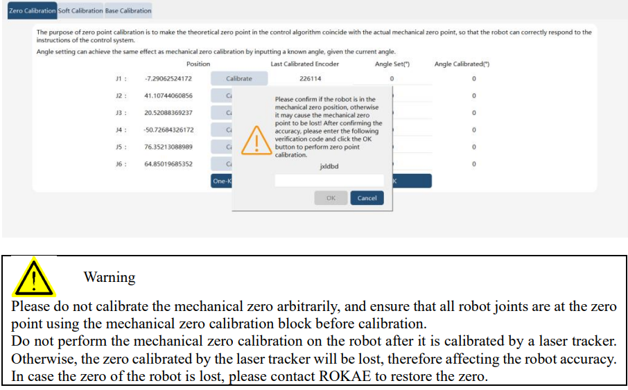
In some space-constrained scenarios, the robot may not be able to return to the mechanical zero, so the "Angle Calibration" function can be used at this time. The prerequisite for using this function is to know the joint angle of the robot at the calibration time, input it into the "Angle Calibration", and then calibrate it, which can achieve the same effect as calibrating at the zero position.
Example:
Taking the xMate7 Pro robot as an example, assuming there is an obstacle above the 4-axis space, the robot cannot reach the vertical state of the mechanical zero and needs to perform zero point calibration. The robot can be adjusted to the right angle state shown in the following figure through jogging. At this point, the 4-axis is 90 degrees. Then, in the "Angle Calibration", enter the current corresponding angle information (the 4-axis: 90 degrees, and the rest: 0 degrees) to proceed.
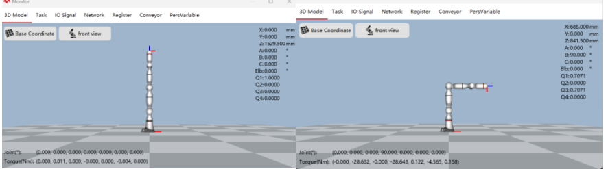
Please note that in the above example, although it is calibrated in a different orientation, the zero of the robot remains in a vertical state. Therefore, if you directly use the  Quick Turn to Zero function after a successful angle calibration by inputting the current angle of the 4-axis at 90 degrees, the robot will still move to the vertical state of the mechanical zero and thus collide with the obstacles! So bear in mind that the Angle Calibration function calibrates the zero. It does not mean that the zero is at the current angle.
9.5.2 Soft calibration
The Soft Calibration function refers to the function of the robot to quickly recover the zero after the zero is lost due to abnormal operations such as encoder battery undervoltage, disassembly of the battery, or accidental touch and removal of multiple loops. Before using this function, it is necessary to manually jog the robot to the zero (the wide and narrow calibration slots are aligned, and the narrow slots are completely located in the wide slots), and this function cannot restore the zero at any angle. The Soft Calibration function is for industrial robots and collaborative robots.
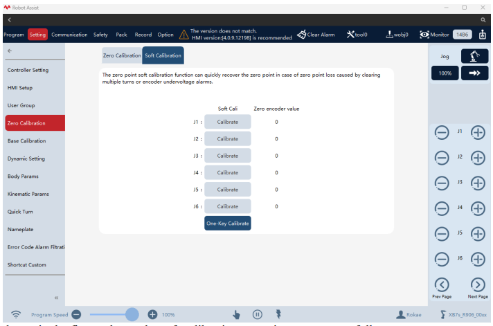
As shown in the figure above, the soft calibration operation steps are as follows:
1. Manually jog the robot to zero (the wide and narrow calibration slots are aligned, and the narrow slots are completely located in the wide slots);
2. Enter the "Main Menu − Settings − Zero Calibration− Soft Calibration" interface;
3. Click the "one-key calibration" button and confirm the pop-up prompt to retrieve the zero, and the zero encoder value displays the encoder value of the zero of each axis;
4. Click the "Calibration" button corresponding to each axis, and confirm the pop-up prompt to retrieve the single-axis zero.
9.5.3 Force sensor calibration
The calibration is aimed at the xMate series of collaborative robots. During the long-term use of the robot, the torque sensor may inevitably produce zero drift, which is manifested as the robot dragging and drifting.
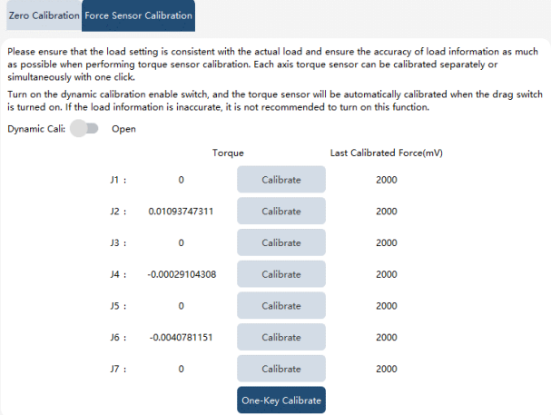
After a similar problem occurs, the robot can be adjusted to the zero position to perform single-axis
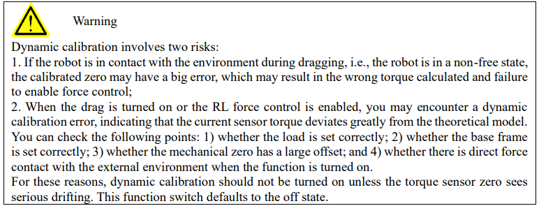
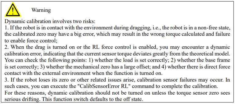
calibration or one-key calibration. If you want to calibrate the force sensor at any position, you can turn on the "Dynamic calibration" switch, and then perform single-axis calibration or one-key calibration. The calibration accuracy of this method may not be as good as that of performing force sensor calibration at the zero position of the robot. In addition, after the dynamic calibration function is turned on, when the force control is turned on in the drag and RL program, the system will automatically zero to ensure the normal use of force control related functions.
9.5.4 Base frame calibration
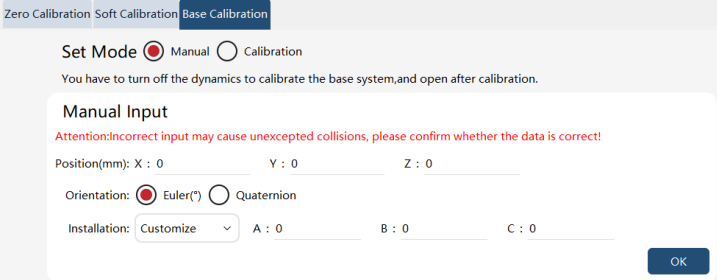
This calibration is aimed at
9.5.5 Force sensor calibration
The calibration is aimed at the xMate series of collaborative robots. During the long-term use of the robot, the torque sensor may inevitably produce zero drift, which is manifested as the robot dragging and drifting.
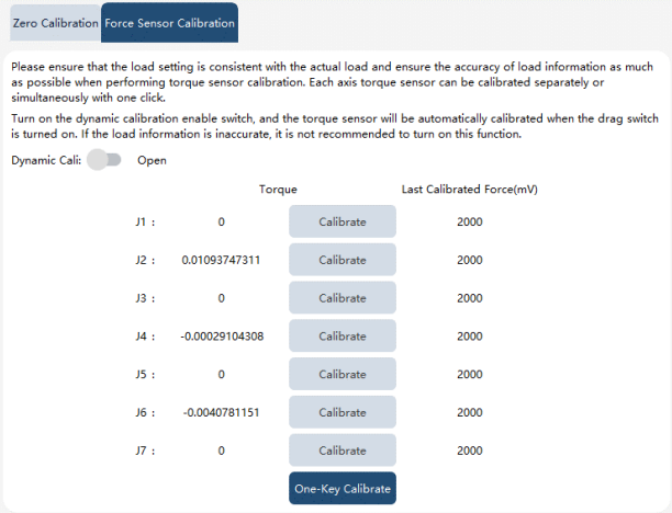
After such issues occur, you can adjust the robot to a suitable position (not necessarily at the mechanical zero), check the load settings, and then perform single-axis calibration or one-click calibration. If you want to calibrate the force sensor at any position, you can turn on the "Dynamic calibration" switch, and then perform single-axis calibration or one-key calibration. The calibration accuracy of this method may not be as good as that of performing force sensor calibration at the zero position of the robot. In addition, after the dynamic calibration function is turned on, when the force control is turned on in the drag and RL program, the system will automatically zero to ensure the normal use of force control related functions.
9.6 Frame calibration
9.6.1 Global tool list
9.6.1.1 Overview
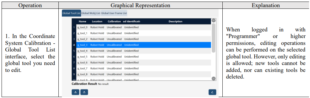
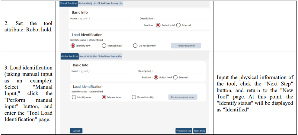
Global tool definition is consistent with tool definition. In the xCore control system, the data type corresponding to global tools is "g_tool_num", with the num ranging from 0 to 15, totaling 16 global tools. Global tools also belong to the tool type. For detailed descriptions of tools, please refer to the "RL commands - Variables" section. Note that global tools differ from tools within individual projects; global tools can be used across all projects.
9.6.1.2 Basic concept
Refer to the basic concepts in 8.12.2 for details.
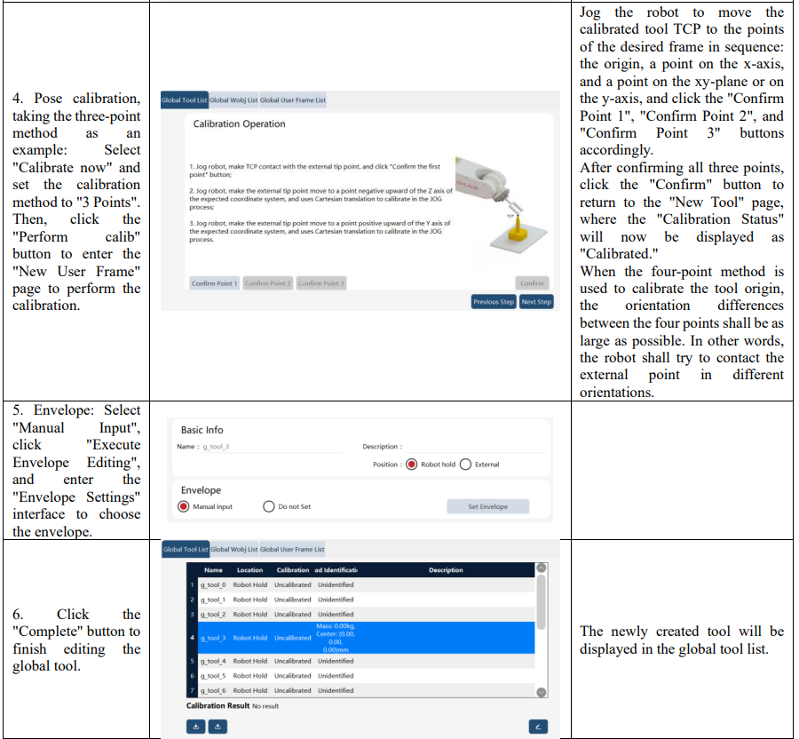
9.6.1.3 Operation example - creating a global handheld tool
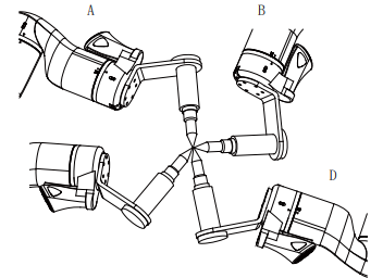
Before the calibration of tool frame, the user needs to prepare a fixed external point, which shall be located within the robot’s working range and can be contacted by the calibrated tool in a very flexible orientation.
9.6.1.4 Operation example - creating a global external tool
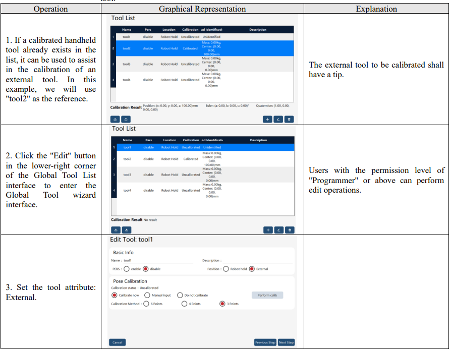
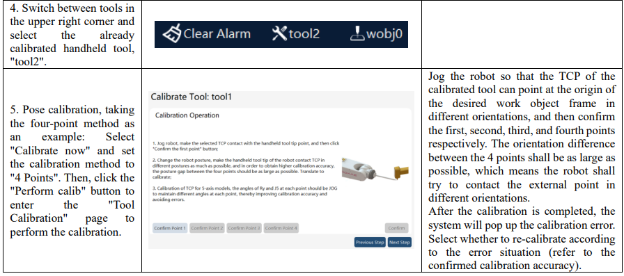
The calibration methods for global external tools are consistent with those for global handheld tools, supporting three methods: six-point method, four-point method, and three-point method.
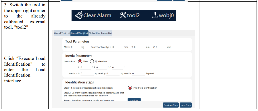
Attention: To calibrate the external tool frame, it is necessary to use the already calibrated handheld tool.
Note:
The external tool must be used together with the corresponding work object, meaning among the Position parameters which are selected at the same time in the tool and work object respectively, one must be External while the other be Robot hold. Otherwise, the system will prompt an error and forbid jogging the robot.
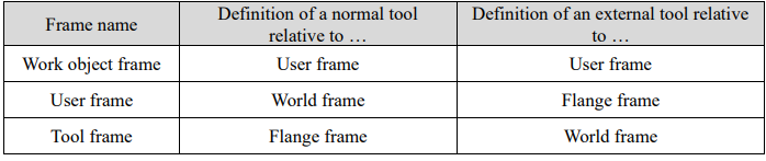
The reference frames for defining tool frames and work frames of external tools differ from those for defining tool frames and work frames of normal tools. You can refer to the following table.
9.6.2 Global work object list
9.6.2.1 Overview
Global work object definition is consistent with work object definition; see 8.13.1 for details. In the xCore control system, the data type corresponding to global work objects is "g_wobj_num", with the num ranging from 0 to 15, totaling 16 global work objects. Global work objects also belong to the work object type. For detailed descriptions of work object, please refer to the "RL commands - Variables" section. Note that global work objects differ from work objects within individual projects; global work objects can be used across all projects.
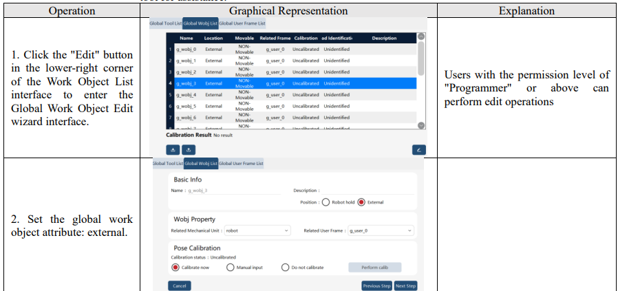
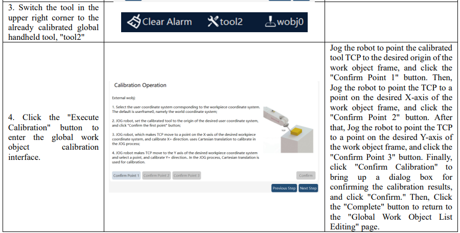
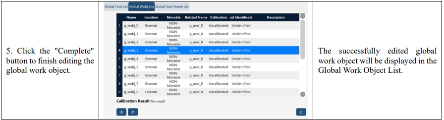
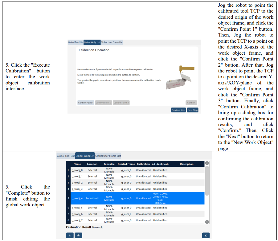
9.6.2.2 Operation example - creating a global external work object
To calibrate the global external work object frame, it is necessary to use an already calibrated handheld tool for assistance
9.6.2.3 Operation example - creating a global handheld work object
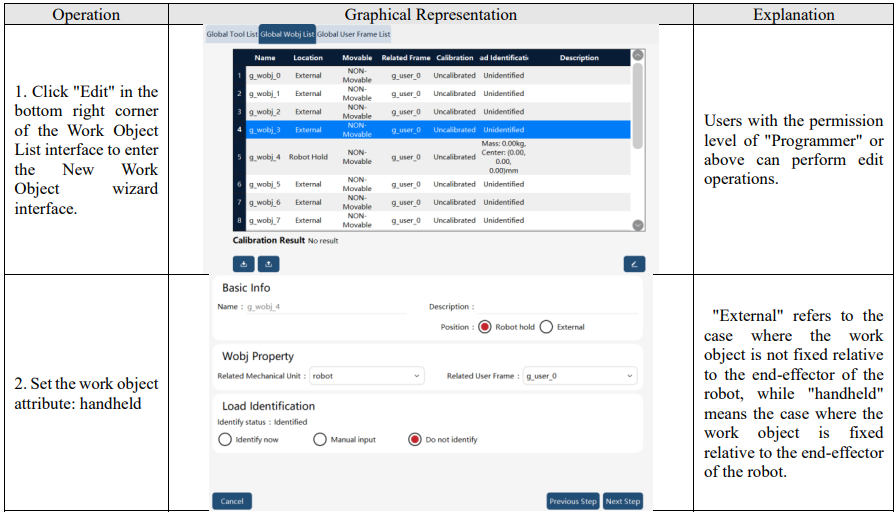
To calibrate the global handheld work object frame, it is necessary to use an already calibrated global external tool for assistance.
9.6.3 Global user frame list
9.6.3.1 Overview
The global user frame serves as a reference frame when defining the work object frame or global work object frame and is not used independently.
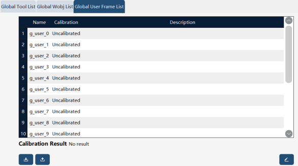
When establishing a global user frame, you can choose "Calibration now", "Manual input" or "Do not calibrate".
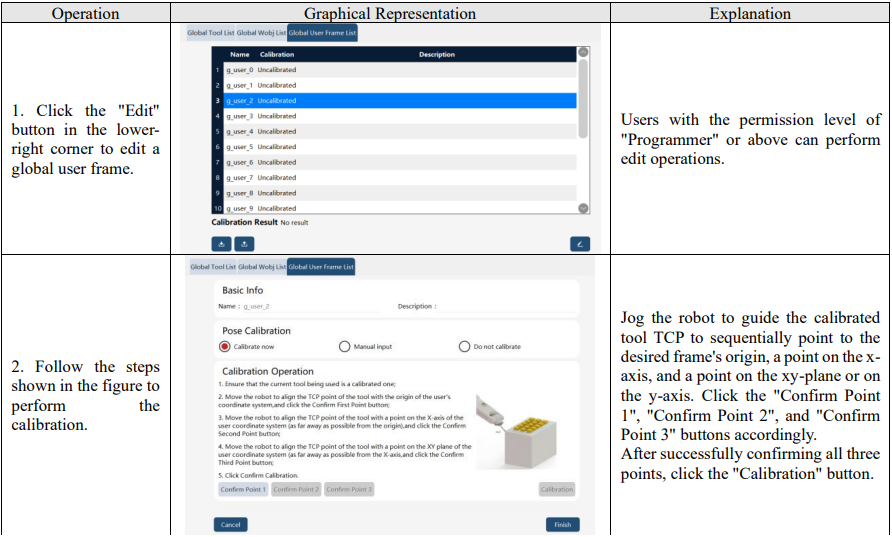
When "Calibration now" is selected, the 3-point method is used to calibrate. Before calibrating the global user frame, the user needs to first calibrate a tool and then use the TCP of the tool to calibrate the user frame. For this, it is recommended to use a tool with tips. "Manual input" is allowed if the global user frame is known in advance. Another option is "Do not calibrate", in which case the global user frame is considered as the world frame by default.
9.6.3.2 Operation examples
9.7 Dynamic settings
The dynamic settings page is used to set the dynamic parameters of the robot. Dynamic settings are related to functions such as robot force control, drag teaching, virtual walls, and collision detection. Please ensure the robot's dynamic settings are reasonable. Otherwise, the above functions may not work properly or may cause the robot to shake abnormally.
9.7.1 Dynamic feedforward
The dynamic feedforward switch determines whether the controller turns on or off the dynamic feedforward function and is turned on by default. Users are not recommended to turn off the dynamic feedforward function by themselves, which may cause jitter when power on and worse trajectory accuracy. The dynamic feedforward should be turned off in certain situations, including base frame calibration when the robot adopts non-front installation and friction identification.

9.7.2 Dynamic constraint
The dynamic constraint switch determines whether the controller turns on or off the dynamic constraint function and is turned on by default. Users are not recommended to turn off the dynamic constraint function by themselves, which may cause motor overload or abnormal shaking.

When the dynamic constraint switch is turned on, two options including "Nominal Dynamic Params" and "Factory Identify Dynamic Params" are available. "Nominal Dynamic Params" means nominal
parameters will be used in the dynamic control. The same models using the "Nominal Dynamic Params" will deliver the exact same motion velocity and takt time when executing the same motion program, yet the motion performance may be weaker, or there may be motor overload. "Factory Identify Dynamic Params" will allow the robot to be in the best dynamic control status for the shortest takt time allowed, and the motor will be protected from overload. But robots running the same motion program may be slightly different in velocity and takt time.
9.7.3 Vibration suppression
The vibration suppression switch determines whether the controller enables the vibration suppression function, which is disabled by default.
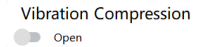
When the vibration suppression switch is turned on, the controller compensates for the flexibility in the robot joints, suppressing vibrations caused by joint flexibility to improve position and path accuracy. Changes in the robot's load parameters can affect the amount of joint flexibility compensation, so it is necessary to set accurate load parameters when using the vibration suppression function.
Note: Currently, the vibration suppression function is supported only on certain models. This feature will be progressively rolled out to other models in the future.
9.8 Body parameters
The body parameters include RD parameters, DH parameters, reduction ratio, overload coefficient, coupling coefficient, and other robot body related data. The parameters on this page directly affect the accuracy of the motion. Please do not modify them without the permission and assistance of the robot manufacturer.
Note: Starting from version 2.3, all models except for the PCB 3-axis/4-axis models use RD parameters.
9.8.1 RD parameters
RD parameters describes the relative pose relationship between the robot's link frames. They are the foundation for robot kinematics.
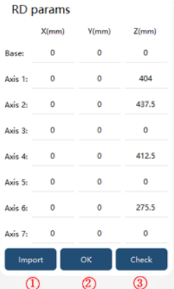

Note:
There will be a set of default parameters before the robot leaves the factory. Users need to confirm the rationality of RD parameters before modifying or importing parameters. After the RD parameter is modified, the controller needs to be restarted to take effect.
9.8.2 DH parameters
DH parameters describe the relative pose relationship between the robot's link frames. They are the foundation for robot kinematics.
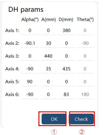

Note:
There will be a set of default parameters before the robot leaves the factory. Users need to confirm the rationality of DH parameters before modifying or importing parameters. After the DH parameters are modified, the controller needs to be restarted for the changes to take effect.
The DH parameters are of the improved type, and users can only modify the parameters Alpha, A, and D.
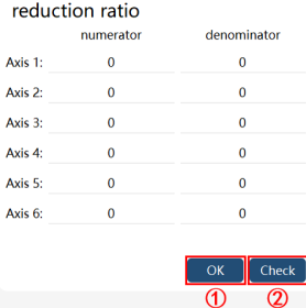
9.8.3 Reduction ratio
The reduction ratio is the parameter of the reducer in each axis of the robot. Do not modify without permission and assistance from the robot manufacturer.

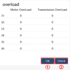
9.8.4 Overload coefficient
Motor overload coefficient setting

9.8.5 Coupling coefficient
In some robots, each axis has a coupling relationship, while the coupling coefficient describes the coupling relationship between these axes. Do not modify without permission and assistance from the robot manufacturer.
9.9 Motion parameters
9.9.1 Basic motion parameters
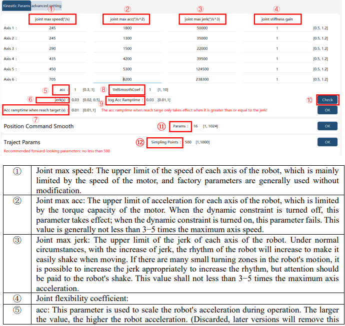
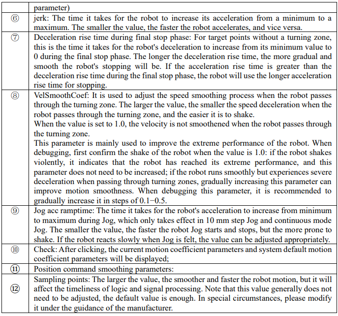
Motion parameters include the maximum speed, the maximum acceleration, and the maximum jerk of each axis of the robot, which affect the motion rhythm and ride of the robot. The robot has a set of default parameters before leaving the factory. Modifying the above parameters may cause the robot to shake abnormally, report errors, and affect the service life of the robot. Please modify it carefully
9.9.2 Advanced settings
9.9.2.1 Safety control
It supports several stop modes, and the stop parameters of each can be set;

Currently, the deceleration to a complete stop at maximum capability is being used. After receiving the stop signal, ensure that the robot path is not offset and at least one motor is planned to stop according to the maximum deceleration capacity.
Considering that the actual performance of different robots can be easily influenced by various factors under different working conditions, this stopping method permits the configuration of a scaling factor, which can be set within the range of [0.1, 1]. When it is set to the maximum value of 1, the robot quickly reaches the motor's maximum capability for deceleration and stopping. When it is set to the minimum value of 0.1, the robot gradually approaches the motor's maximum capability, resulting in a smoother deceleration and stop. The larger the scaling factor, the more quickly the robot reaches the motor's maximum torque value, resulting in a more rapid stop. Conversely, the smaller the scaling factor, the more gradually the robot approaches the motor's maximum torque value, leading to a smoother and more gradual stop.
Additionally, the stop coefficient for manual mode (Stop 0) and the stop coefficient for automatic mode (Stop 1) can be set independently.
9.9.2.2 Search command max stop distance
When a Search command is used and the stop mode is selected for a quick stop, the distance traveled by the robot TCP from the receipt of the stop signal to the full stop of the robot shall not exceed this value.

9.9.2.3 Minimum turning zone radius
The minimum allowable turning zone size is specified by the turning zone radius. This parameter can be used to avoid generating a turning zone too short and to make motion smoother. When the control system detects that the length of a trajectory is below the set value of this parameter and the trajectory needs to generate a turning zone, the control system will automatically combine the trajectory and the adjacent trajectories into one trajectory and generate a turning zone with an appropriate length. The larger the value, the longer the minimum turning zone and the smoother the robot passes through the turning zone. When this parameter is set to 0, the control system strictly follows the parameters to generate the turning zone.

9.9.2.4 Stacking debug mode
The stacking debug mode option will only be displayed and available when the model type is CR, SR, and Industrial Six-Axis Robot (NB, XB) series models. When this mode is turned on, two Jog frames corresponding to four-axis locking are added: singularity avoidance and parallel base.
Note: CR series 5-axis models turn on this mode by default. At this time, Jog under the base frame corresponds to the singularity avoidance frame of the 6-axis model.
9.9.2.5 Default Conf
The "RL" option in Defualt Conf is used to set whether motion commands strictly adhere to the movement constraints defined by the Conf information for each point after reloading an RL project.
Note: After modifying this option, you need to run PPTOMAIN to apply the changes and make the option effective.
The "Point Move to" option in Default Conf is used to set whether motion commands strictly adhere to the movement constraints defined by the Conf information for each point when performing "Point Move to" operations.
Note: By default, all the 4 buttons in the Default Conf are enabled until modifications are made in this interface.

9.10 Force control parameters
9.10.1 Force control parameters
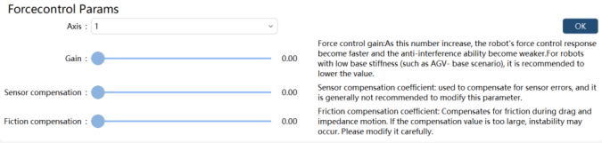
Force control gain: It is used to adjust the response speed of robot force control. Note that the larger the value, the faster the robot force control response, but the weaker the anti-interference ability. The default value is 1.0. If the rigidity of the robot base is low, such as when placing the robot on a mobile chassis, the force control gain value should be appropriately reduced. When the end-effector load is close to the upper limit in the load pattern, the use of dragging and impedance may cause shaking, at this time the force control gain should be appropriately reduced, and the base stiffness should be adjusted to low if the control system version is below V2.0. Sensor compensation coefficient: It is used to compensate for sensor error, generally which does not need to be modified. If there is a force moving in the positive direction of the joint during the robot's dragging process, this parameter value can be appropriately reduced. On the contrary, if there is a force moving in the negative direction of the joint, this parameter value can be appropriately increased. The default value is 0.5.
Friction compensation coefficient: It is used to compensate for friction during dragging and impedance motion. Too large compensation coefficient may cause instability, so please modify it with caution. The default value is 0.5.
Note:
Force control parameters are for advanced developers, please modify them carefully
9.10.2 Force control model
There are three options for the force control model, and this function is a developer's option, please modify it carefully. The default nominal model is used after the initialization and when no modification is made.

9.10.3 Drag optimization
Improve the drag experience by handling the stop at the end of the drag. This function is enabled by default after the initialization and when no modification is made.

9.10.4 Drag without end-effector button operations
The collaborative robot supports dragging operations without the need to press the drag button on the end-effector. By enabling the automatic drag mode switch, the robot can be directly dragged after activating the drag mode, without requiring any button presses on the end-effector.

Note:
1. Once the automatic drag mode switch is enabled, ensure safety precautions are followed when activating the drag mode. If the robot exhibits any abnormal behavior, immediately press the emergency stop (E-Stop) button;
2. The end-effector drag button becomes inactive once the automatic drag mode switch is enabled.
9.10.5 Force control model deviation threshold setting
When the drag mode is enabled, the collaborative robot will self-check the deviation between the sensor torque and the theoretical dynamics model torque. If the deviation is significant, enabling the drag mode will fail. If the drag mode still fails to initiate after verifying that the load settings are correct, you can appropriately increase the force control model deviation threshold.

Note:
1. When the force control model deviation threshold setting is not enabled, the controller uses default
values
9.10.6 Dual-channel sensor deviation threshold setting
When the drag mode is enabled, the collaborative robot will self-check the deviation between the voltage values of the two sensor channels. If the deviation is significant, the drag mode initiation will fail, and a warning indicating a large voltage deviation will be displayed. In this case, you can appropriately increase the dual-channel sensor deviation threshold.

Note:
1. When the dual-channel sensor deviation threshold setting is not enabled, the controller uses default values
9.11 Quick adjustment
The user can customize several commonly used positions, and quickly adjust the robot's position through buttons or commands. It supports custom poses including the drag pose, transport pose, and Home pose. The above poses have default values for specific models, and also support user customization.
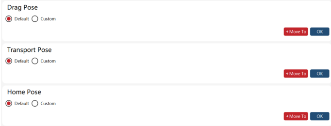
The Home pose is quite unique, in addition to defining the reference position, it also requires setting a set of offsets. When the difference between the current position of the robot and the reference position is less than the offset, it is considered that the robot is in the Home pose, and the "Home state" of the system IO and the "sta_home" of the register will have corresponding outputs.
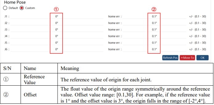
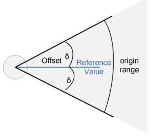
The relationship between the origin range, the reference value, and the offset value is shown as follows:
This function can also turn the robot to some special orientations quickly while keeping the TCP position and elbow (only available for 7-axis robots) unchanged, including the flange parallel to the ground, the X axis of the tool frame perpendicular to the ground, the Y axis of the tool frame perpendicular to the ground, and the Z axis of the tool frame perpendicular to the ground.

The use of the quick adjustment function is similar to JOG operation, requiring the robot to be powered on through the enable button in manual mode; continuously pressing the "Move to" button, the robot moves to the target pose through joint space, and the speed of the motion process can be adjusted through JOG speed. If the power is turned off or the "Move to" button is released during motion, the robot will stop moving.
Note: When using the quick adjustment function to adjust the pose, please turn on the soft limit to avoid unexpected collisions.
9.12 Electronic nameplate
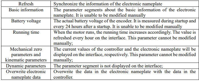
The electronic nameplate designed for some industrial robots is installed in the robot body. It is mainly used to save the data of the robot body and avoid the loss of basic data after the replacement of the industrial computer or the controller cabinet.
The software function of electronic nameplates is mainly divided into two parts: Controller and RobotAssist software. The controller carries out the data reading, verification, and coverage of the electronic nameplate, while the RobotAssist software issues operation commands related to the electronic nameplate and displays data.
After the controller is turned on, it will first check if there is an electronic nameplate. If there is an electronic nameplate, it will read the data normally, perform data verification, and store the verification result. If there is no electronic nameplate and the user does not choose to use the electronic nameplate, it will directly operate with the controller data. If there is no electronic nameplate and the user chooses to use the electronic nameplate, a prompt "there is no electronic nameplate" will appear. After Robot Assist is connected to the controller, it will first check the verification results of the electronics nameplate data in the controller, and give different pop-up prompts based on the verification results. Users can simply follow the pop-up prompts.
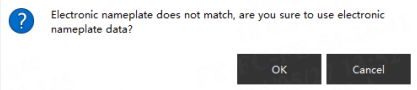
If the data in the electronic nameplate is successfully used, it will overwrite the data in the controller by default.
There are three situations where pop-up prompts appear:
(1) If an electronic nameplate is detected and its data is different from that in the controller, a pop-up window will prompt "Do you want to use the data in the electronic nameplate?". Select "Yes" to use the data in the electronic nameplate and "No" to use the data in the controller;
(2) After choosing to use the data in the electronic nameplate once, the electronic nameplate data will be used by default after restart. If the data in the controller is again different from that in the electronic nameplate, a pop-up window will prompt, "Do you want to use the data in the electronic nameplate?";
(3) If the electronic nameplate is not detected during startup, the controller data will be used by default.
If the electronic nameplate data is used once and cannot be detected after restart, a pop-up window will prompt "Do you want to use the data in the controller?". Select "Yes", the controller data will be used normally. Select "No", the controller will be in a malfunction state and cannot be operated. In this case, restart the controller to solve the problem.

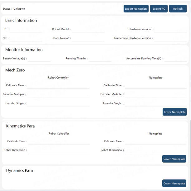
Click "Settings"->"Electronic nameplate" in turn on the HMI software interface, and the information in the electronic nameplate will appear. If the controller detects an electronic nameplate, whether the electronic nameplate is used or not, this interface will display the information of the relevant parameter segments in the electronic nameplate. The status of the electronic nameplate can be determined through the status field on this interface, with three parameters representing: electronic nameplate status, matching of electronic nameplate data with controller data, and whether the "use electronic nameplate" button is clicked when starting up (as long as the "use electronic nameplate data" button is clicked, regardless of whether the data is successfully used, this position will be displayed as used), as shown in the following figure:

If an electronic nameplate is not detected during startup, the interface is as shown in the figure below:



9.13 Error code alarm filtering
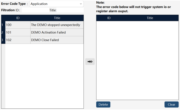
When an error level alarm occurs in xCore, it will trigger the system IO or register output high level bound to the alarm state. If the customer does not want certain alarms to trigger alarm state outputs (system IO or registers), this function can be used for setting.
9.14 Custom buttons
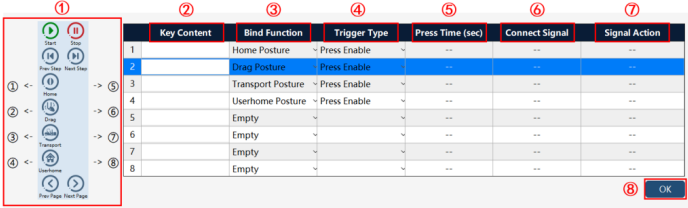
By custom buttons, some convenient functions can be bound to several physical buttons on xPad2.