13. Object Dictionary
13.1 General Objects
Device Type (1000h)

The data description is as following.

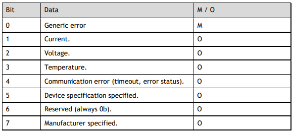
Error Register (1001h)

The data description is as following.
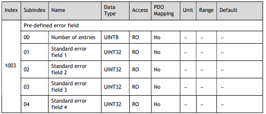
Pre-defined error field (1003h)

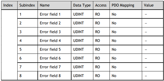
(1): This value indicates the maximum number of times the alarm occurs when the servo is turned on, and the
maximum value is 8.
The data description is as following.

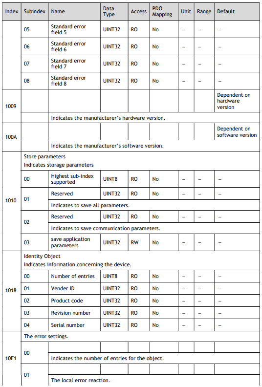
Store parameters (1010h)
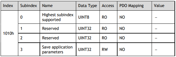
Save the value of the object into the relevant parameter by writing a specific signature to 1010-03h. So that, the servo can load the value of the parameter to the relevant object as an initial value.
The signature is saved.

The relationship between Index and Parameter State by saving is described as below.
In the case of 1010-03h, the data description is as following.
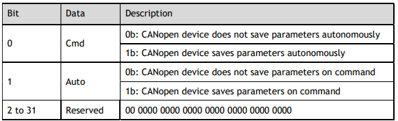
NOTE: Commands that save objects to FRAM can only be executed when it is not in Servo ON state. Save Autonomously means you do not need to write save to the object when the slave saves the object value to FRAM.
Identity Object (1018h)
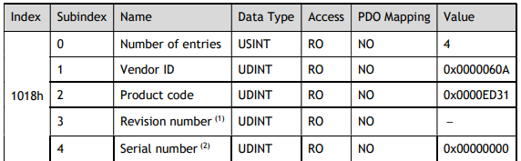
(1): The revision number is stored as follows:
The major version identifies a specific CANopen over EtherCAT (CoE) behaviour. If the CoE functionality is expanded, the major version has to be increased. The minor version number identifies different versions with the same behaviour.
(2): Serial number is not used (always 0).
13.2 PDO Mapping Objects
The CANopen over EtherCAT (CoE) protocol allows the user to map objects to process data objects (PDOs) in order to use the PDOs for real-time data transfer.
Objects can be combined in PDO data via PDO Mapping and PDO Assignment.
The data description of PDO Mapping Objects is as following.
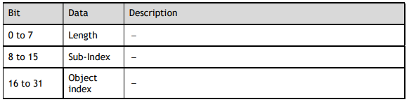
The objects mapped to PDOs can be changed only when the EtherCAT (CoE) Network Module is in the PreOperational state.
There are 4 receiving PDOs (RxPDOs) and 4 transmit PDOs (TxPDOs). Each PDO Mapping can be assigned up to 8 objects, and the total assignment is not more than 32 bytes.
The procedure of PDO mapping is as following:
1. Disable the assignments between the Sync Manager and PDOs:
Set subindex 00h in objects 1C12h and 1C13h to 0.
2. Disable the assignments of PDOs:
Set subindex 00h in objects (1600h to 1603h) and (1A00h to 1A03h) to 0.
3. Set all of the mapping entries for the PDO mapping objects:
Set objects (1600h to 1603h) and (1A00h to 1A03h).
4. Set the number of mapping entries for the PDO mapping objects:
Set subindex 00h in objects (1600h to 1603h) and (1A00h to 1A03h).
5. Set the assignments between the Sync Manager and PDOs:
Set subindex 01h in objects 1C12h and 1C13h.
6. Enable the assignments between the Sync Manager and PDOs:
Set subindex 00h in objects 1C12h and 1C13h to 1.
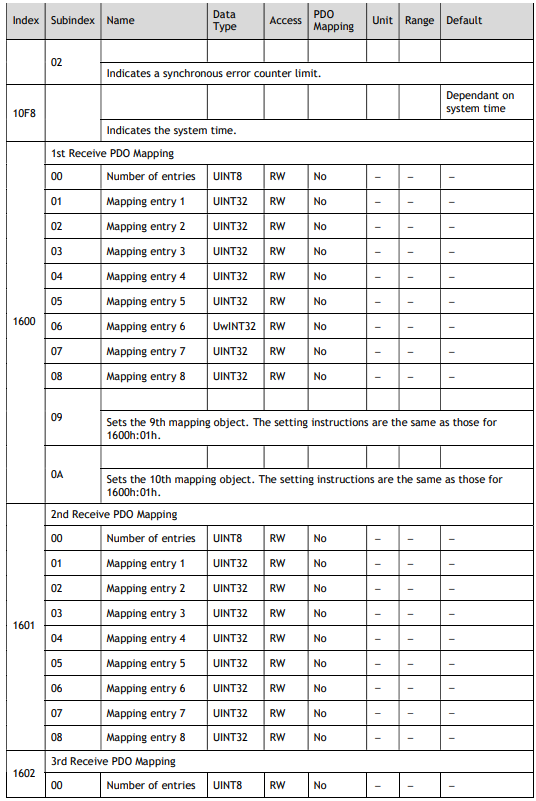
1st Receive PDO Mapping
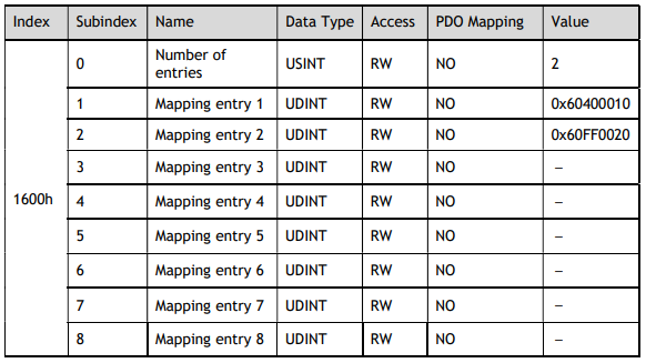
2nd Receive PDO Mapping
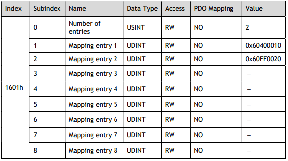
3rd Receive PDO Mapping
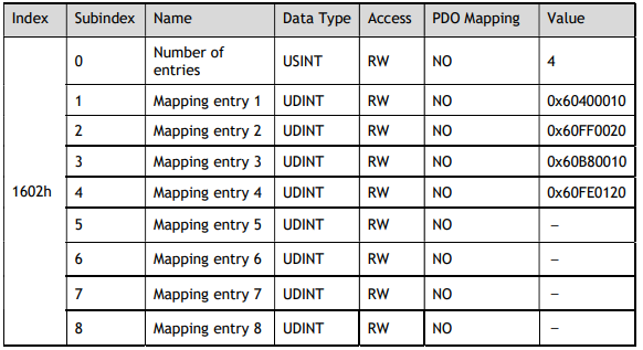
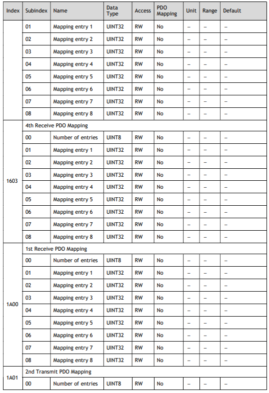
4th Receive PDO Mapping
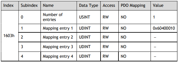
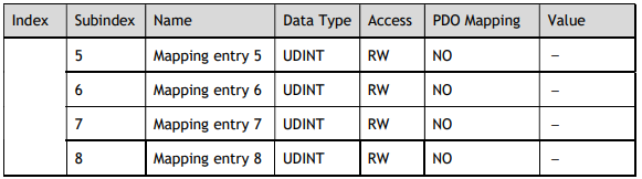
1st Transmit PDO Mapping
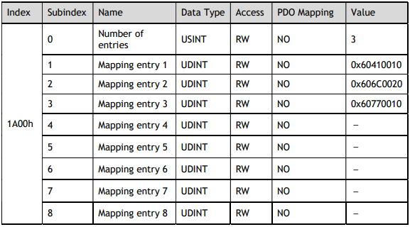
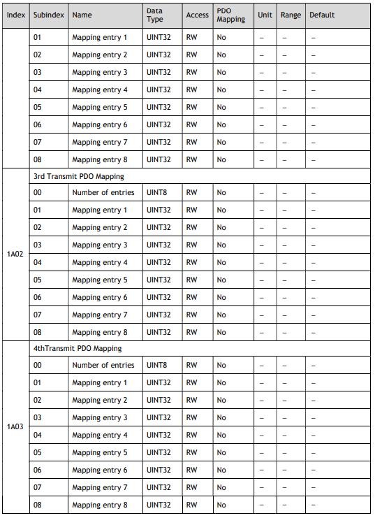
2nd Transmit PDO Mapping
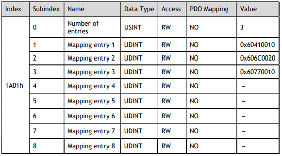
3rd Transmit PDO Mapping
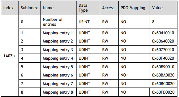
4th Transmit PDO Mapping
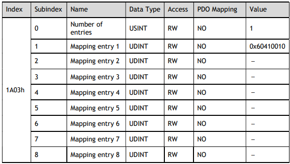
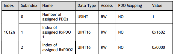
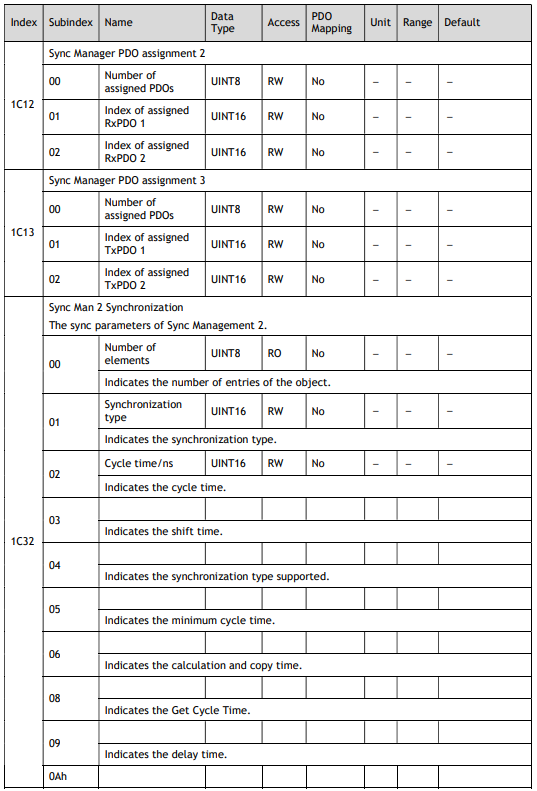
Sync Manage2 PDO Assignment
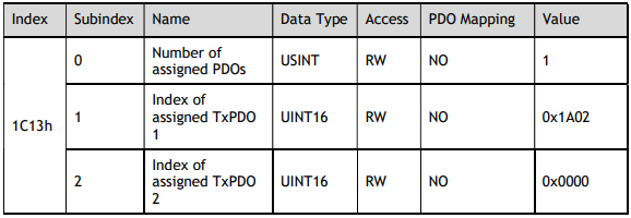
Sync Manage3 PDO Assignment
13.3 Parameters Table
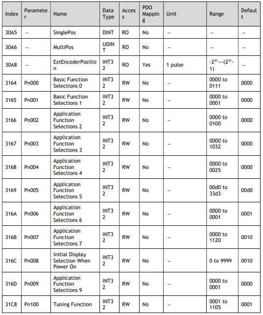
SinglePos (30A5h)

MultiPos (30A6h)

Pn000 Basic Function Selections 0 (3164h)

NOTE: Other parameters are the same as 3164h, refers to Chapter 12Parameters.
13.4 Device Control
Error Code (603Fh)


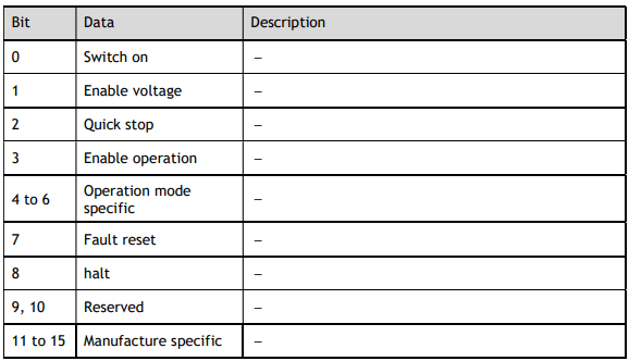
Control Word (6040h)
This object controls the device and operation mode.

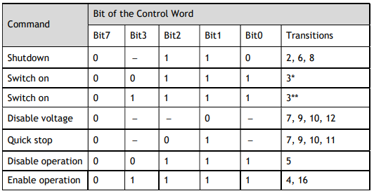
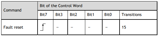
Bit0 to Bit3, and Bit7: These bits function as the control command for the Servo Drive’s state.
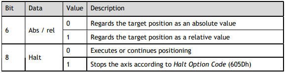
The description of Bit4 and Bit5 in PP mode is as following.

The description of Bit6 and Bit8 in PP mode is as following.
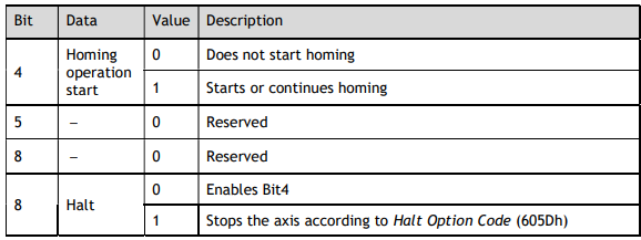
The description of Bit4, Bit5, Bit6 and Bit8 in HM mode is as following.
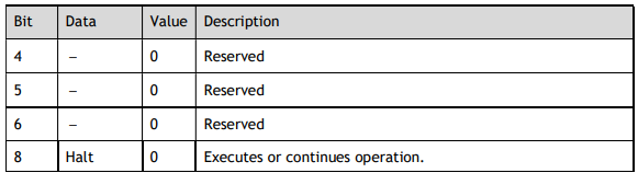
The description of Bit4, Bit5, Bit6 and Bit8 in CSP, CSV or CST mode is as following.

The description of Bit4, Bit5, Bit6 and Bit8 in IP mode is as following.
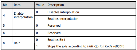
The description of Bit4, Bit5, Bit6 and Bit8 in PV mode is as following.
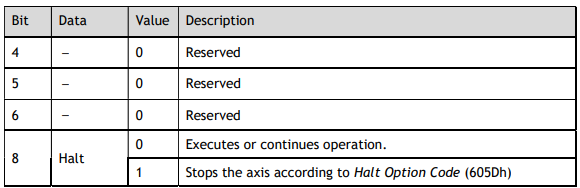
Status Word (6041h)

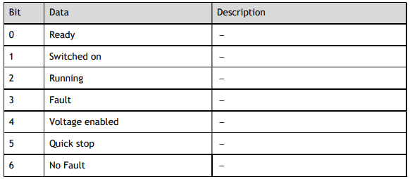
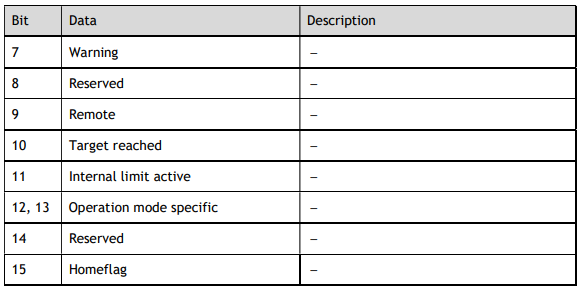
Bit0 to Bit7: Current State of Servo Drive:
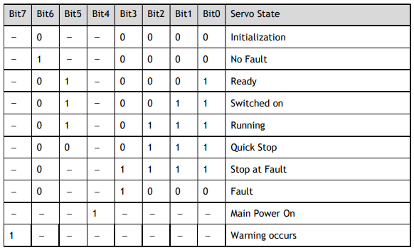
Bit11: The internal limit is activated (set to 1) when the N-OT or P-OT signal was activated.
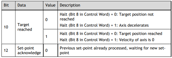
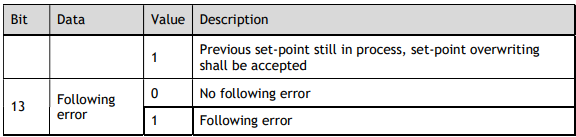
The description of Bit10, Bit12 and Bit13 in PP mode is as following.
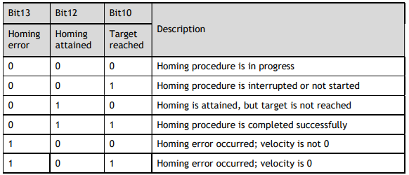
The description of Bit10, Bit12 and Bit13 in HM mode is as following.
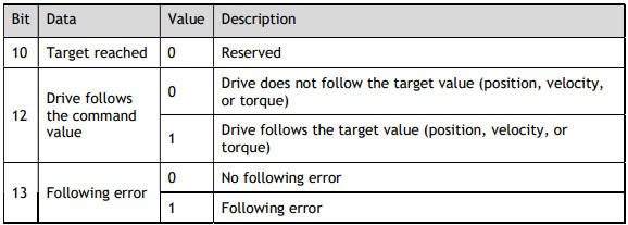
The description of Bit10, Bit12 and Bit13 in CSP, CSV or CST mode is as following
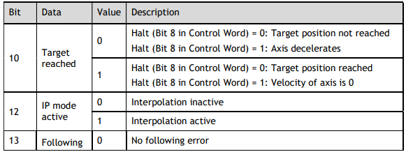
The description of Bit10, Bit12 and Bit13 in IP mode is as following.

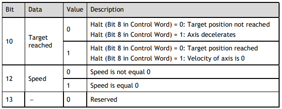
The description of Bit10, Bit12 and Bit13 in PV mode is as following.
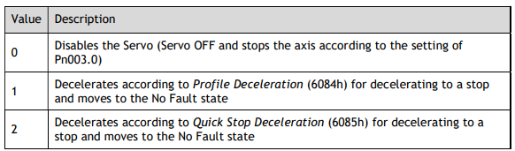
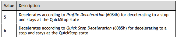
Quick Stop Option Code (605Ah)
This object determines what operation will be performed if a Quick Stop is executed.

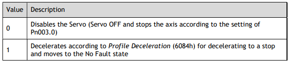
Shutdown Option Code (605Bh)
This object defines the operation that is performed if there is a move from Operation Enable state to Ready state.

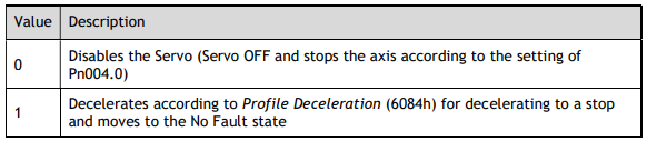
Disable Operation Option Code (605Ch)
This object defines the operation that is performed if there is a move from Operation Enable state to Switched ON state.

Halt Option Code (605Dh)
This object defines the operation that is performed if bit 8 (Halt) in Control Word is active.


605Eh (Fault Reaction Option Code)
This object defines the operation that is performed when an alarm is detected in the Servo System.


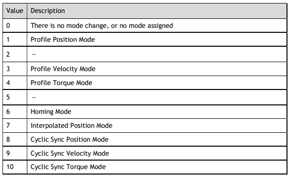
Modes of Operation (6060h)
This object is used to select the operation mode. The Servo System gives the actual operation mode in the Modes of Operation Display object.

Modes of Operation Display (6061h)
This object gives the current mode of operation.

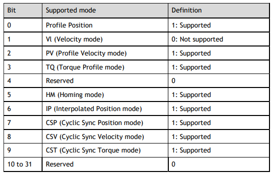
Supported Drive Modes (6502h)
This object gives the operation modes that are supported by the device.

13.5 Profile Position Mode
Target Position (607Ah)
This object contains the target position for the Profile Position Mode or Cyclic Sync Position Mode. In Profile Position Mode, the value of this object is interpreted as either an absolute or relative value depending on the Abs/Rel Flag in Control Word. In Cyclic Sync Position Mode, the value is always interpreted as an absolute value.

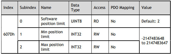
Software Position Limit (607Dh)
This object defines the absolute positions of the limits to the target position (position demand value). Every target position is checked against these limits.
The limit positions are specified in user-defined position reference units, the same as for target positions, and are always relative to the machine home position.
The limit values are corrected internally for the home offset as given below. The target positions are compared with the corrected values.
Corrected minimum position limit = Min position limit – Home offset (607Ch)
Corrected maximum position limit = Max position limit – Home offset (607Ch)
The software position limits are enabled at the following times:
When homing is completed
When an absolute encoder is connected
The software limits are enabled if Min position limit < Max position limit.
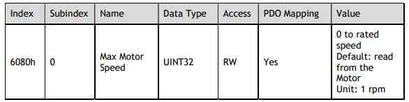
Max Motor Speed (6080h)
This object defines the maximum speed for protecting the Motor.
Profile Velocity (6081h)
This object contains the final movement speed at the end of acceleration for a Profile Mode operation.

Profile Acceleration (6083h)
This object specifies the acceleration rate for PP Mode and PV Mode.

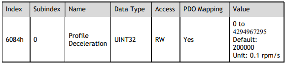
Profile Deceleration (6084h)
This object specifies the acceleration rate for PP Mode and PV Mode.
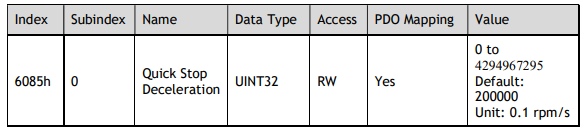
Quick Stop Deceleration (6085h)
This object contains the deceleration rate that is used to stop the Motor if the Quick Stop Option Code (605Ah) is set to 2 and the Quick Stop command is given, or Halt Option Code (605Dh) is set to 2 and the Halt command is given.
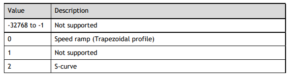
Motion Profile Type (6086h)
This object specifies the motion profile for the trajectory generator

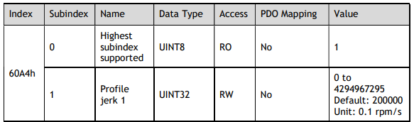
Profile jerk (60A4h)
This object is regarded as the jerk in PP mode only if Motion Profile Type (6086h) is set to 2
13.6 Homing Mode
Home Offset (607Ch)
This object contains the offset between the zero position for the application and the machine home position (found during homing).

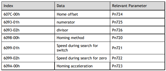
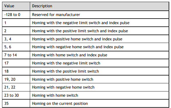
Homing Method (6098h)
This object specifies the homing method.

Homing Speeds (6099h)
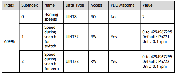
NOTE: This value is limited by 607Fh and 6080h.
Homing Acceleration (609Ah)

13.7 Position Control Function
Position Demand Value (6062h)
This object specifies the current reference position in user position reference units.
This value is 0 in Velocity Mode.

Position Actual Internal Value (6063h)
This object gives the current feedback position in encoder pulse units.
For the absolute encoder and the homing operation has been completed, this value represents the actual position value of the Motor encoder.
For the incremental encoder or the homing operation has not been completed, this value represents the number of pulses (encoder units).
This value is 0 in Velocity Mode.

Position Actual Value (6064h)
This object gives the current feedback position in user position reference units

Following Error Window (6065h)
This object defines the detection range for the following error (bit 13 of Status Word).
If the position deviation exceeds the following error window for the following error time out (6066h), bit13 in Status Word changes to 1 to indicate following error.

Following Error Time Out (6066h)
If the position deviation exceeds the following error window for the time specified in this object, bit-13 in Status Word changes to 1 to indicate following error.

Following Error Actual Value (60F4h)
This object provides the current following error.

Position Window (6067h)
This object defines the positioning completed width for the target position. When the Servo Drive has completed outputting the reference to the target position and the time specified in position window time (6068h) has passed after the distance between the target position and the position actual value is within the value of this object, bit-10 (target reached) in Status Word changes to 1.

Position Window Time (6068h)

Position Demand Internal Value (60FCh)
This object gives the output of the trajectory generator during position control (the position that is input to the position loop). The value is given in encoder pulses.
This value is 0 in Velocity Mode.

13.8 Interpolated Position Mode
Interpolation sub mode select (60C0h)
This object is used to select the submode for the Interpolated Position Mode and Cyclic Sync Position Mode.


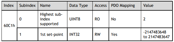
Interpolation Data Record (60C1h)
This object gives the interpolation position reference for Interpolated Position Mode.
Interpolation Time Period (60C2h)
The Interpolation Time Period indicates the period of updating 607Ah or 60C1-01h. In the CSP or IP mode, if the DC synchronization mode is selected, the value must be the same as the DC synchronization period; and if the SM2 Event mode is selected, the value of 1C32-02h is consistent with the interpolation period and the actual SM2 Event period, otherwise Sync Error will occur.
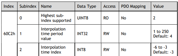
NOTE: Interpolation time = (Interpolation time period (60C2h: 01)) × 10Interpolation time index (60C2h: 02) [s]
The interpolation period must be an integer multiple of 125us and greater than 125us.
13.9 Cyclic Synchronous Position Mode
Velocity Offset (60B1h)
In Cyclic Synchronous Position Mode, this object contains the speed feedforward value.

Torque Offset (60B2h)
In Cyclic Synchronous Position Mode or Cyclic Synchronous Velocity Mode, this object contains the torque feedforward value.
In Cyclic Synchronous Torque Mode, this object contains the offset value to add to the torque reference.

13.10 Profile Velocity/Cyclic Synchronous Velocity Mode
Velocity sensor actual value (6069h)
This object contains the current speed from encoder.

Velocity Demand Value (606Bh)
This object contains the output value from the velocity trajectory generator or the output value from the position control function (i.e., the input reference for the speed loop).

Velocity Actual Value (606Ch)
This object contains the Motor speed.

Velocity Window (606Dh)
This object sets the speed coincidence detection width.
When the time specified in Velocity Window Time (606Eh) has passed after the difference between the target speed and the Velocity Actual Value is within the setting of the Velocity Window, Bit10 in Status Word is set to 1.

Velocity Window Time (606Eh)
When the time specified in Velocity Window Time (606Eh) has passed after the difference between the target speed and the Velocity Actual Value is within the setting of the Velocity Window, Bit10 in Status Word is set to 1.

Velocity Threshold (606Fh)
When the time specified in Velocity Threshold Time (6070h) has passed after the Velocity Actual Value is greater than Velocity Threshold (606F), Bit12 in Status Word is set to 1.

Velocity Threshold Time (6070h)
When the time specified in Velocity Threshold Time (6070h) has passed after the Velocity Actual Value is greater than Velocity Threshold (606F), Bit12 in Status Word is set to 1.

Target Velocity (60FFh)
This object specifies the target speed for Profile Velocity Mode or Cyclic Synchronous Velocity Mode in user defined speed reference units.

13.11 Profile Torque / Cyclic Synchronous Torque Mode
Target Torque (6071h)
This object specifies the input torque reference value for Torque Control Mode. Set the value in units of 0.1% of the Motor rated torque.

Torque Demand Value (6074h)
This object gives the currently output torque reference value. The value is given in units of 0.1% of the Motor rated torque.

Torque Slope (6087h)
This object sets the torque output slope to use in Profile Torque Mode. Set the value as the rate of change per second (0.1%/s) in respect to the Motor rated torque.

Torque Actual Value (6077h)
This object contains the torque reference output value.

13.12 Torque Limit Function
Max. Torque (6072h)
This object sets the maximum output torque for the Motor in PT mode. Set the value in units of 0.1% of the Motor rated torque.

Positive Torque Limit Value (60E0h)
This object sets the positive torque limit. Set the value in units of 0.1% of the Motor rated torque.
The positive torque limit value is the smaller of 6072h and 60E0h.

Negative Torque Limit Value (60E1h)
This object sets the negative torque limit. Set the value in units of 0.1% of the Motor rated torque.
The negative torque limit value is the smaller of 6072h and 60E1h.

13.13 Digital Inputs/Outputs
Digital Inputs (60FDh)

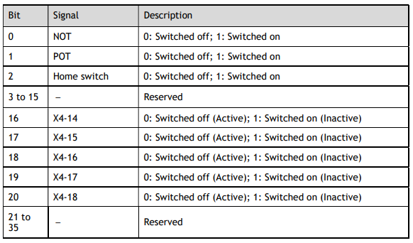
If the corresponding bit of Pn509 and Pn510 has been set to Remote, the input signal on X4 terminal is only used as remote input IO, and the Drive will ignore its status.
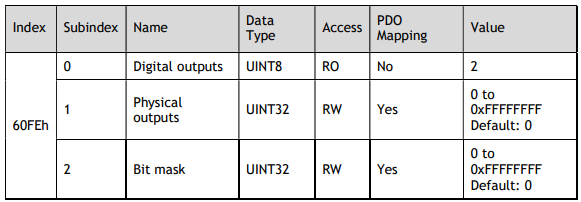
Digital Outputs (60FEh)
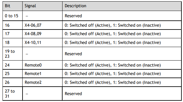
This object controls the status of both general-purpose output signals and remote output signals from X4 on the Drive. 60FE-01h is used to control the status of the output signals. 60FE-02h determines which output signals in subindex 1 are enabled.
The Bit16 to Bit19 in 60FE-01h can only assign to the general-purpose output signals on X4 and set the Bit mask (60EF-02h) to 1 for enabling them. And then, according to the settings of Pn509 and Pn510 to allocate the desired signals, also you can choose whether to reverse them by the setting of Pn516 and Pn517.
For the bits transmitted on the bus, you also need to set Pn512 and Pn513 to enable it.
The Bit24 to Bit27 in 60FE-01h can assign to the remote output signals on X4, and according to the setting of Pn511 to allocate the desired signals, using as a remote IO for the master station.
13.14 Object Dictionary List
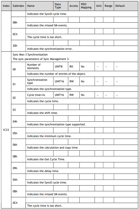
Group 1000h

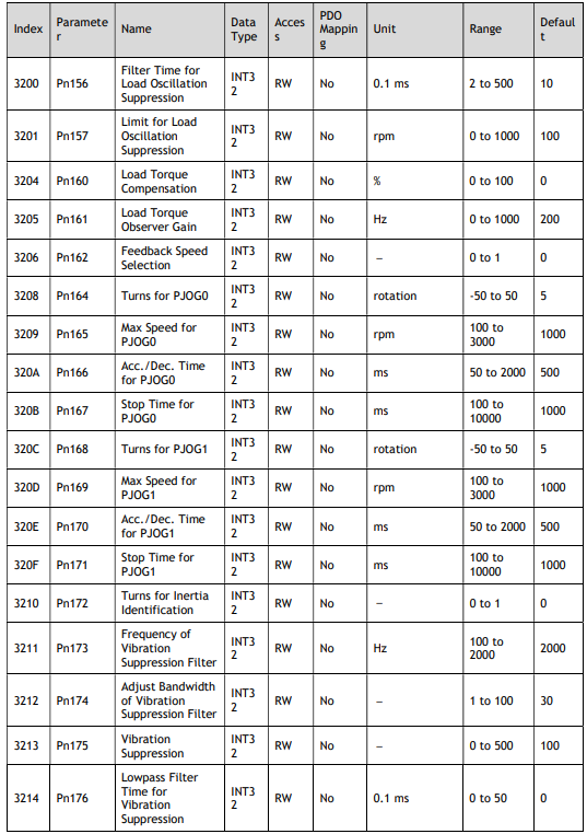
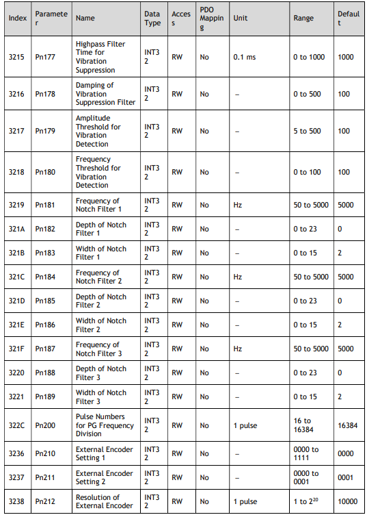
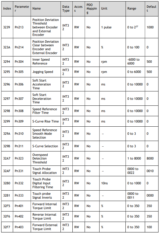
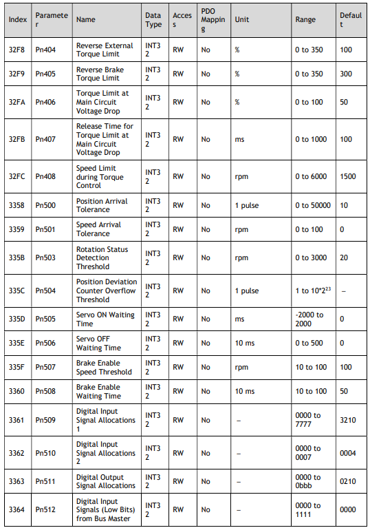
Group 3000h
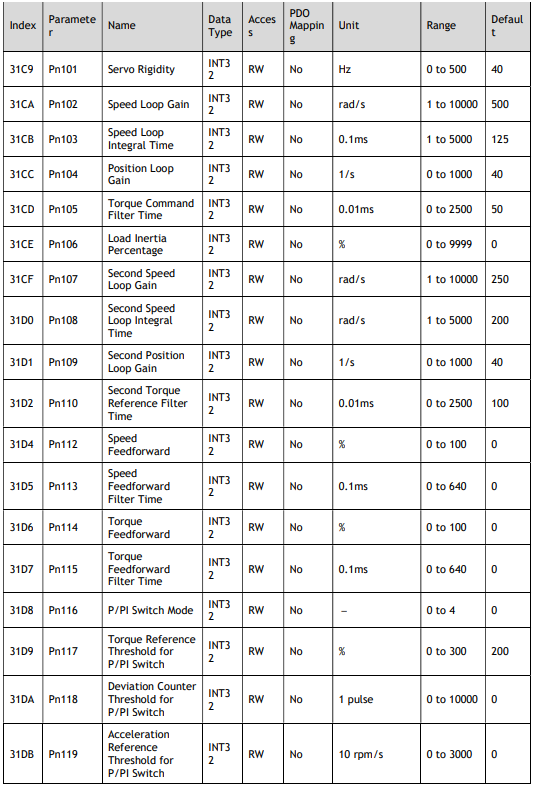
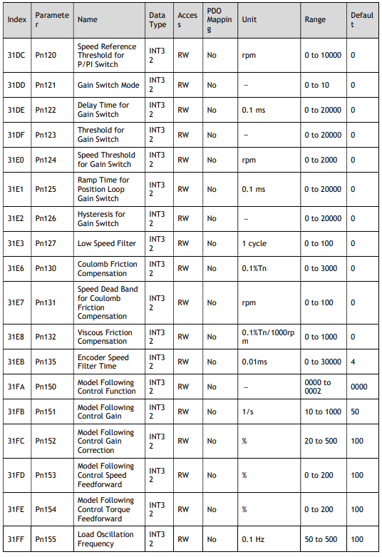
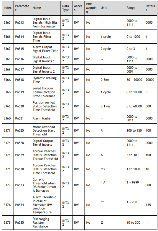
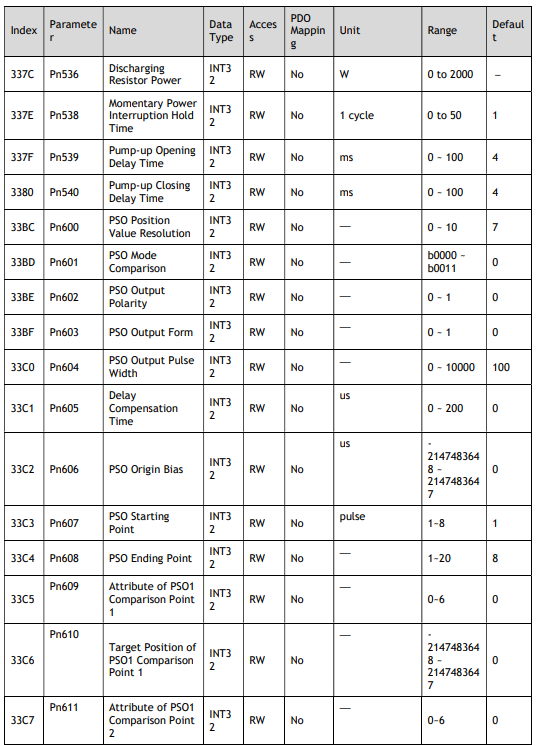
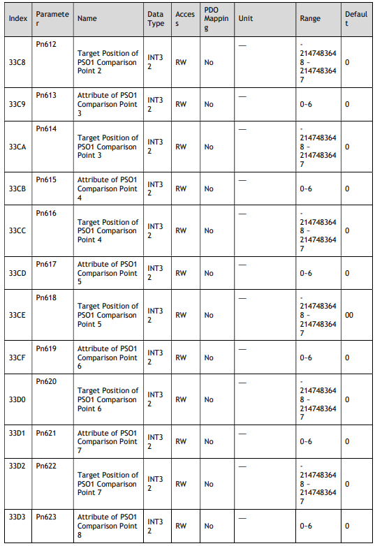
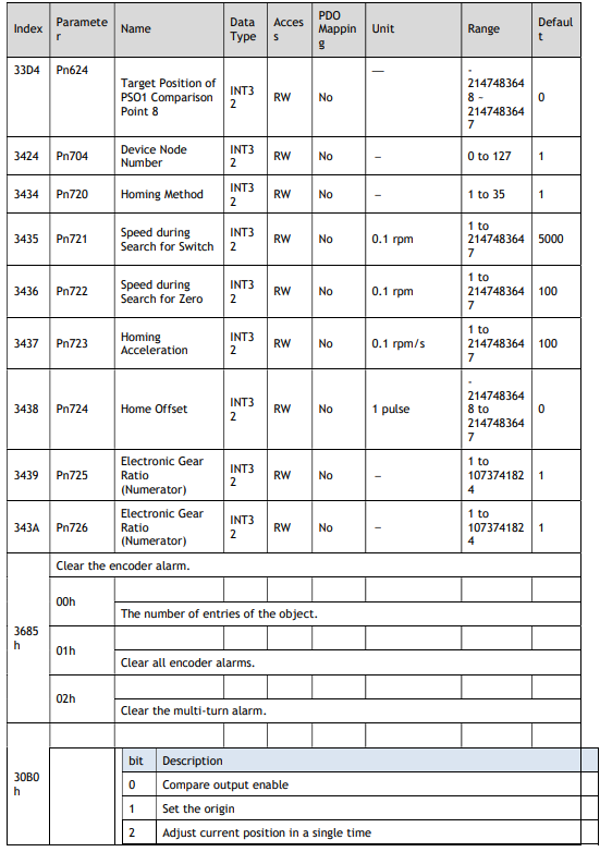
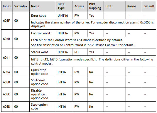
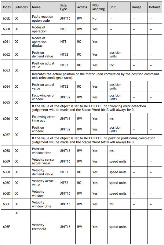
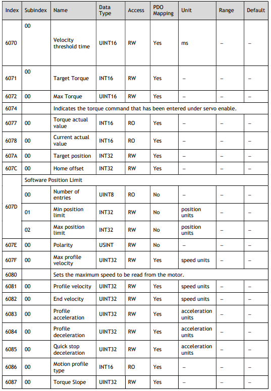
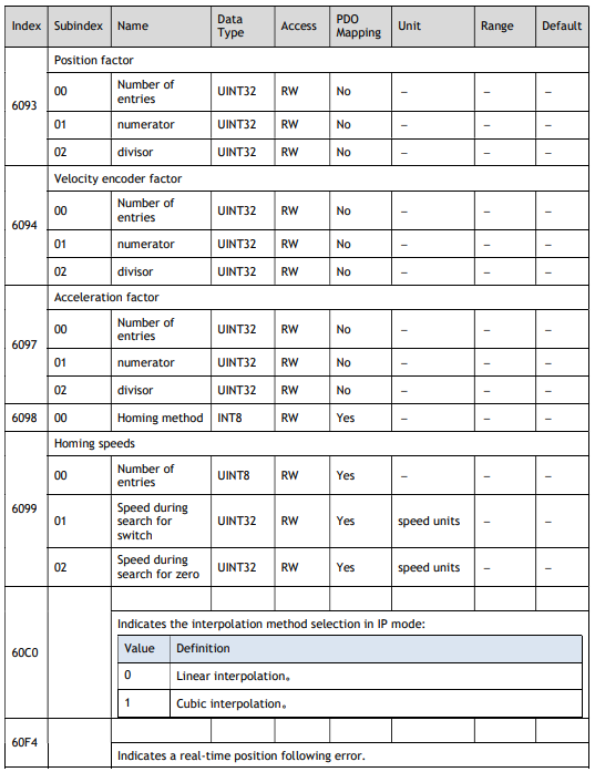
Group 6000h