4. Basic Settings
You can implement the functions of parameter setting, display, monitoring, alarm, adjustment, etc. of the Drive in the following two ways.
Use the Panel Operator of the Drive
Use the Motion Perfect V5.3 or above (Recommended)
4.1 Panel Operator
4.1.1 Key Names and Functions
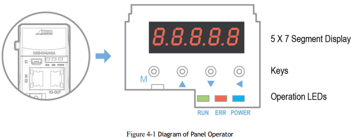
There is a Panel Operator on the front of the Drive, as is shown in Figure 4-1.
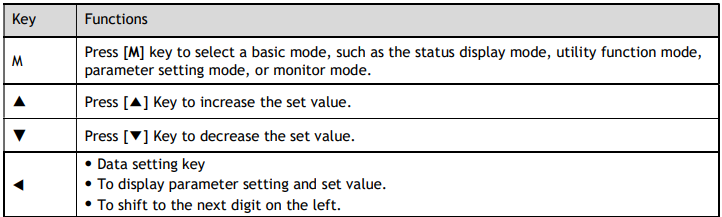
The names and functions of the keys on the Panel Operator are as follows.
4.1.2 Basic Mode Selection
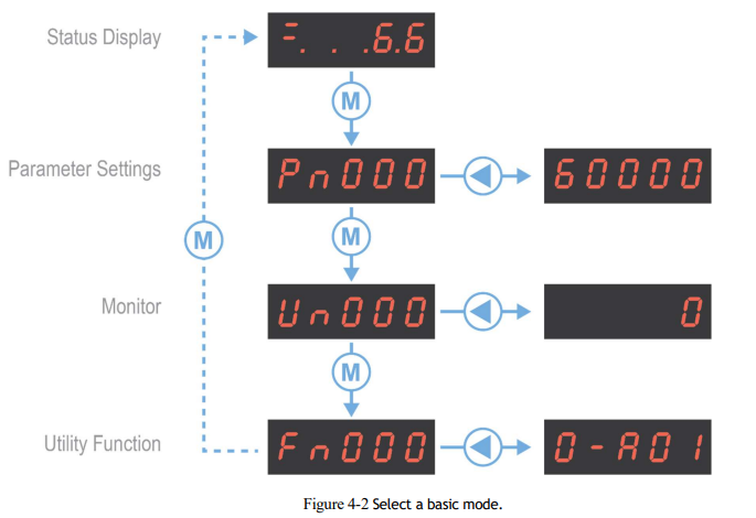
The basic modes include Status Display Mode, Parameter Setting Mode, Utility Function Mode, and Monitor Mode. Select a basic mode with [M] key to display the operation status, set parameters and operation references, as is shown in Figure 4-2.
4.1.3 Status Display Mode
Power ON the Drive and wait for a while, the Panel Operator will initially display the Servo Status.
The information displayed by the status is divided into two parts:
The first two digits are called Bit Data, what indicates the signal states during the operation of Drive.
The last three digits are called Code, what indicates the operation states of Drive.
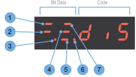
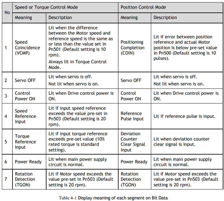
The display meaning of each segment on Bit Data are shown in Table 4-1, and they have different meanings under Speed or Torque Control Mode and Position Control Mode.
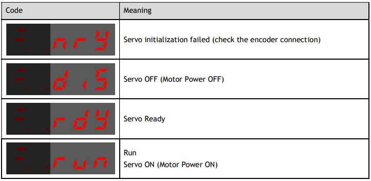
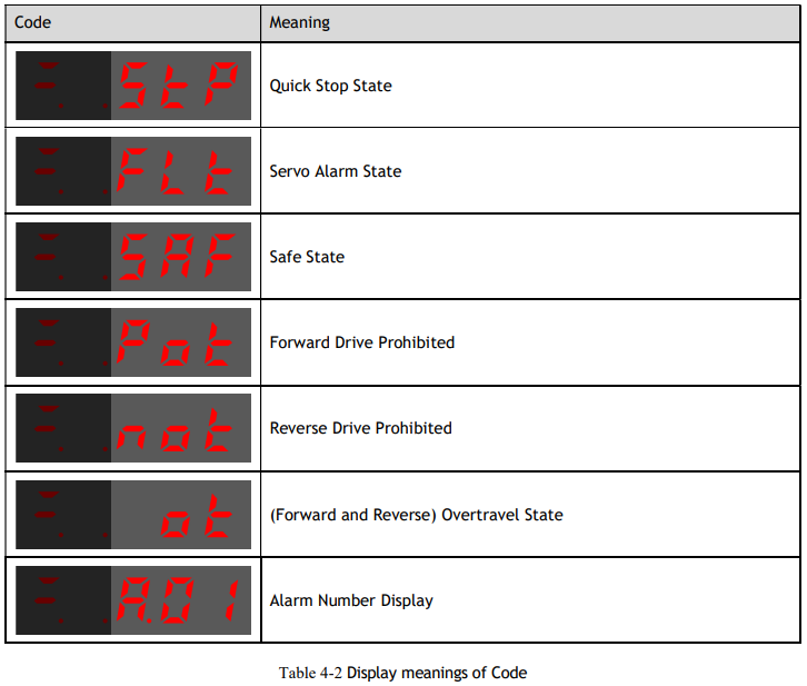
The display meanings of Code are shown in Table 4-2

4.1.4 Parameter Setting Mode
Functions can be selected or adjusted by setting parameters. There are two types of parameters.
Function Parameters: the functions allocated to each digit of the Panel Operator can be selected.
Adjustment Parameters: a parameter is set to a value within the specified range of the parameter.
For a description of the parameter settings, please refer to the section Chapter 12 Parameters.
Function Parameters Setting
The example below shows how to change parameter Pn003 (Application Function Selections 3) from 0000 to 1032.
Step 1 Press [M] key several times to select the Parameter Setting Mode.
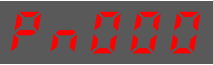
Step 2 Press [▲] key or [▼] key to select the parameter Pn003.
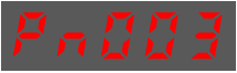
Step 3 Press [◄] key to display the current value of Pn003.
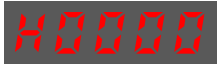
Step 4 Press and hold [◄] key for 1 second or more, and then a flashing decimal point will appear at the bottom right of the 5th digit.

Step 5 Press [▲] key twice, changing the value of the 5th digit from 0 to 2.
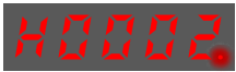
Step 6 Press [◄] key once, moving the flashing decimal point to the 4th digit.

Step 7 Press [▲] key three times, changing the value of the 4th digit from 0 to 3

Step 8 Press [◄] key twice, moving the flashing decimal point to the 2nd digit.
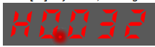
Step 9 Press [▲] key once, changing the value of the 2nd digit from 0 to 1.

Step 10 Press and hold [◄] key for 1 second or more to return to the display of the Pn003 parameter value or press the [M] key to return to the display of the Pn003.
----End

Adjustment Parameters Setting
The example below shows how to change parameter Pn102 (Speed Loop Gain) from 100 to 85.
Step 1 Press [M] key several times to select the Parameter Setting Mode.
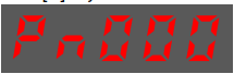
Step 2 Press [▲] key or [▼] key to select the parameter Pn102
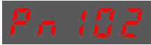
Step 3 Press [◄] key to display the current value of Pn102.
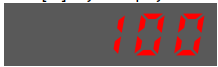
Step 4 Press [▲] key or [▼] key to change the value to 00085.
Press and hold [▲] key or [▼] key to jump the setting value quickly.
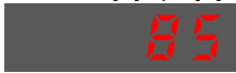
Step 5 Press [◄] key or [M] key to return to the display of Pn102.
----End
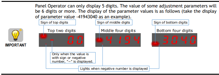
The example below shows how to change parameter Pn504 (Deviation Counter Overflow Alarm) from 41943040 to 42943240.
Step 1 Press [M] key several times to select the Parameter Setting Mode.
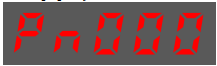
Step 2 Press [▲] key or [▼] key to select the parameter Pn504

Step 3 Press [◄] key to display bottom four digits of the current value of Pn504.
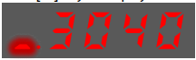
Step 4 Press and hold [◄] key for 1 second or more, and then a flashing decimal point will appear at the bottom right of the 5th digit.

Step 5 Press [◄] key twice, moving the flashing decimal point to the 3rd digit.

Step 6 Press [▲] key twice, changing the value of the 3rd digit from 0 to 2.

Step 7 Press [◄] key four times, moving the flashing decimal point to the 3rd of middle four digits.
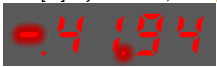
Step 8 Press [▲] key once, changing the value of the 3rd digit from 1 to 2.
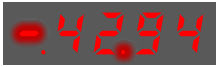
Step 9 Press and hold [◄] key for 1 second or more to return to the display of the Pn504 parameter value or 8press the [M] key to return to the display of the Pn504.
----End
4.1.5 Monitor Mode
The Monitor Mode can be used for monitoring the reference values, I/O signal status, and Drive internal status.
The Monitor Mode can be selected during Motor operation.
Select Monitor Mode
The example below shows how to display, the contents of monitor number Un003 (when the Motor rotates at 100).
Step 1 Press [M] key several times to select the Monitor Mode.
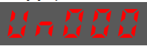
Step 2 Press [▲] key or [▼] key to select the monitor number Un003.
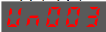
Step 3 Press [◄] key to display the data of Un003.

Step 4 Press [◄] key to return to the display of Un003.
----End
Contents of Monitor Mode Display
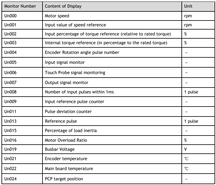
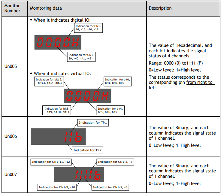
The status (low level or high level) of input signal allocated to each input terminal is displayed