
7. Tuning
Tuning is the process of satisfying the servo performance by adjusting the parameters involved in the control law.
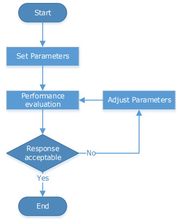
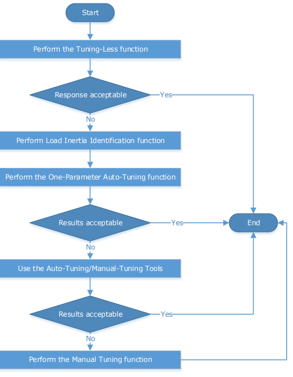
The process of tuning is usually an iterative process; the figure below shows the general flow
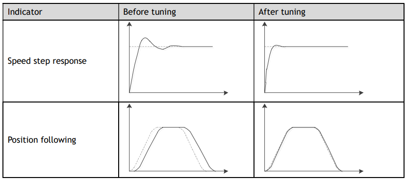
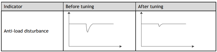
There are various indicators used to evaluate servo performance including bandwidth, response time, overshoot, steady state error, anti-load disturbance, speed ripple fluctuation, torque ripple, etc. The importance of these will depending on the application.
The table below shows examples of speed vs time graphs showing the comparison of before and after tuning.
7.1 Tuning Process
When tuning a servo drive is if helpful to understand the servo control principle used. The figure below shows the servo control block diagram. The position loop, the speed loop and the torque loop are cascaded structures, corresponding to the position control mode, the speed control mode and the torque control mode respectively.
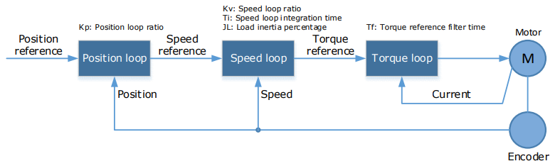
NOTE: only the basic tuning parameters during the tuning are shown in the figure.
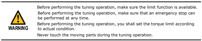
Generally, for tuning the drive follow the process below.

7.2 Tuning Modes
The drive supports 3 different tuning modes and different features are available in each mode.
Tuning-less: the drive performs auto-tuning to obtain a stable response regardless of the type of machine or changes in the load.
One-Parameter Auto-Tuning: similar to the tuning-less function but requires an inertia measurement of the load and uses a rigidity parameter to control the system bandwidth.
Manual Tuning: all gain terms are manually adjusted
The tuning mode can be changed from the Tuning page in the drive commissioning screens. Click on the ‘Change Tuning Mode’ button.

This will launch a wizard to guide the change of tuning mode.
Alternatively, the tuning mode can be changed by directly writing to parameter Pn100.0.
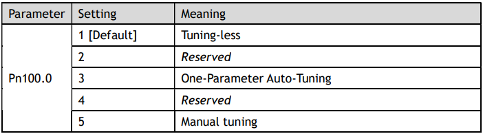
Once the tuning mode has been changed the drive will require a re-start for the new selection to apply.
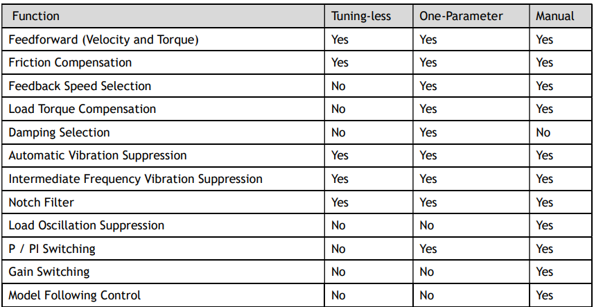
The table below show a summary functions available in each mode:
7.2.1 Tuningless
In Tuning-less mode the drive performs auto-tuning to obtain a stable response regardless of the type of machine or changes in the load. Autotuning is started when the servo is turned on.
The tuning-less function uses an Autotune parameters adjustment module that updates the position loop and speed loop parameters in real time based on the servo operating state (position, speed, current). The figure below shows the block diagram in tuning-less.
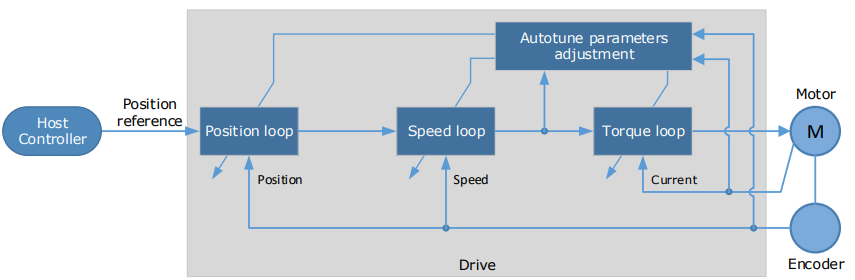
When using the tuning-less function, the following parameters are automatically adjusted.
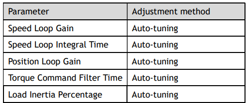
NOTE: The gain terms used by the tuning-less model are not shown in the drive parameters.
Use Case
Applicable for applications where the motor / load inertia mismatch is no more than 30 times.
Applicable for applications of any motor speed.
Parameters

Changing the tuning mode will require the drive to be restarted.
Restrictions
The following table shows a summary of functions available in tuning-less mode

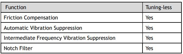
7.2.2 One-Parameter Auto Tuning
This tuning function is similar to the tuning-less function, using an Autotune parameters adjustment module that updates the position loop and speed loop parameters in real time based on the servo operating state (position, speed, current).
One-Parameter Auto Tuning may offer some advantages over Tuning-less mode due to:
Tuning is based on a proper load inertia percentage so tends to offer improved performance.
The user selection of rigidity means that the tuning mode can be applied to more operating conditions.
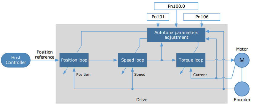
One-Parameter Auto Tuning requires an inertia measurement of the load. The drive can measure the load inertia using the Inertia Detection tool, which can be launched from the Tuning page in the drive commissioning screens
This will launch a wizard to guide the process of inertia detection.
Alternatively, the inertia can be entered by directly writing to parameter Pn106.

The stiffness of the control is selected by a rigidity parameter. This can be adjusted by a slider on the
Tuning page in the drive commissioning screens.
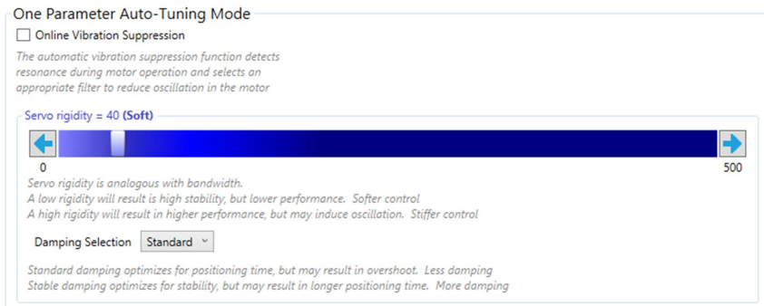
Alternatively, the rigidity can be entered by directly writing to parameter Pn101.

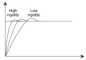
A lower number corresponds to a lower rigidity, less stiff. This will provide a slower response.
A higher number corresponds to a higher rigidity, more stiff. This will provide a faster response but taken too far may result in oscillation.
When using the One-Parameter Auto-Tuning function, the following parameters are automatically adjusted.
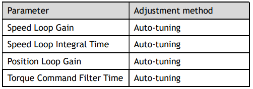
NOTE: The gain terms used by the tuning-less model are not shown in the drive parameters.
Use Case
Applicable for applications where the motor / load inertia mismatch is no more than 50 times
Applicable for applications of any motor speed.
Parameters
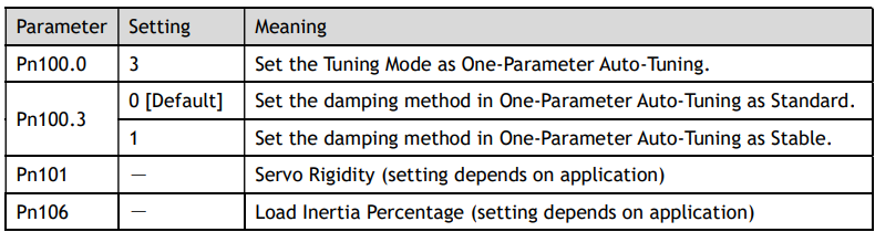
Changing the tuning mode will require the drive to be restarted.
Restrictions
The following table shows a summary of functions available in one-parameter auto-tuning mode
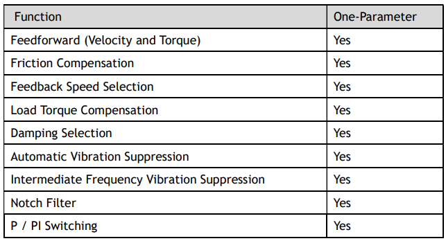
7.2.3 Manual Tuning
In the Manual Tuning, the gain parameters are manually adjusted without using the autotune parameter adjustment module, until the desired performance is achieved.