3. MC464 EXPANSION MODULES
Assembly
A maximum of 7 half height modules or 3 full height modules may be fitted to the MC464. A system may be made using any combination of half and full height modules providing that the full height modules are the last to be attached.
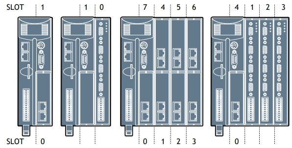
MODULE SLOT NUMBERS
SLOT Numbers are allocated by the system software in order, left to right, starting with the lower bus. Lower modules are allocated slots 0 to m, then the upper modules become slots m+1 to n. Finally, the Sync Encoder Port is allocated slot n+1. The Sync Encoder Port has SLOT number -1 in addition to the one allocated (1) in this sequence.
FITTING EXPANSION MODULES
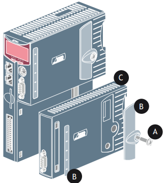
• Remove the 2 covers (B) if fitted to the MC464 or to the previous expansion module (C).
• Locate the 2 hooks at the front of the module, while holding the rear out at an angle
• Push forward to engage the hooks and at the same time swing the rear of the module in so as to locate the connector.
• Press the connector “home” once it is located.
• Tighten the screw (A) using the tool provided or a small coin
• Clip the provided covers (B) in place as shown.
Removing modules is the reversal of the above procedure.
If the system is to be panel mounted, a kit (P8) comprising 2 x panel mounting brackets and 2 x countersunk screws may be purchaced separately from your Trio distributor.
RTEX Interface (P871)
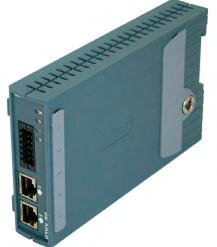
For use with Panasonic amplifiers supporting the Panasonic Real Time Express (RTEX) network. Allows Plug & Play interconnection with Shielded twisted pair (TIA/EIA-568B CAT5e or more) Ethernet cables.
A single interface supports up to 32 axes on the RTEX network. The module comes with 2 axes enabled. Further axes can be enabled with Trio’s Feature Enable Codes.
REALTIME EXPRESS
The P871 communicates with up to 32 servo amplifiers using Ethernet Real Time Express. The physical layer is standard Ethernet connected in a ring. Each node has a transmit socket and a receive socket to allow easy connection. The maxium cable length between any 2 nodes is 60 meters and the overall network length is limited to 200 meters.
RJ45 CONNECTOR (TX)
(Top connector)100Mbps Panasonic RTEX transmit – connect to receive of first drive.

RJ45 CONNECTOR (RX)
(Bottom connector) 100Mbps Panasonic RTEX
receive – connect to transmit of last drive.
TIME BASED REGISTRATION
Time based registration uses a 10MHz clock to record the time of a registration event which is then referenced to time stamps on the axis position from the digital drive network. An accurate registration position is then calculated. The 10MHz clock gives a time resolution of 100nsec. The position and speed of the axis are recorded so that the user can compensate for any fixed delays in the registration circuit.
Any time based registration input can be assigned to any Digital or Virtual axis. This makes the registration very flexible and enables multiple registration channels per axis. Each registration channel can be armed independently and assigned to an axis at any time.
REGISTRATION CONNECTOR
R0-R7 registration inputs (24V).
0V common 0V return.
Registration inputs can be allocated to any axis by software.

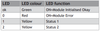
LED FUNCTIONS
Sercos Interface (P872)
The sercos interface module is designed to control up to 16 servo amplifiers using the standard sercos fibre-optic ring. Benefits of this system include full isolation from the amplifiers and greatly reduced wiring.
For use with any sercos IEC61491 compliant drive. The module allows control of up to 16 axes via sercos with cycle times down to 250usec. Multiple sercos interface modules can be used to increase
axes count to 64.
2, 4, 8 and 16 Mbit / sec
Software settable intensity
SERCOS CONNECTIONS
Sercos is connected by 1mm polymer or glass fibre optic cable terminated with 9mm FSMA connectors. The sercos ring is completed by connecting TX to RX in a series loop. The maximum fibre cable length between 2 nodes is 40m for plastic optical fibre (POF) and 200m for hard clad silica (HCS). The total length for POF is 680m and 3,400 for HCS.
CONNECTOR (RX)
(Top connector) sercos fibre-optic transmit. 9mm FSMA.

CONNECTOR (TX)
(Bottom connector) sercos fibre-optic receive. 9mm FSMA.

TIME BASED REGISTRATION
Time based registration uses a 10MHz clock to record the time of a registration event which is then referenced to time stamps on the axis position from the digital drive network. An accurate registration position is then calculated. The 10MHz clock gives a time resolution of 100nsec. The position and speed of the axis are recorded so that the user can compensate for any fixed delays in the registration circuit.
Any time based registration input can be assigned to any Digital or Virtual axis. This makes the registration very flexible and enables multiple registration channels per axis. Each registration channel can be armed independently and assigned to an axis on the fly.
REGISTRATION CONNECTOR
R0 - R7 registration inputs (24V).
R0V registration common 0V return.
Registration inputs can be allocated to any axis by software.

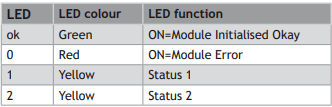
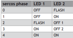
LED FUNCTIONS
SLM Interface (P873)
For use with drives supporting the Control Techniques SLM protocol. Each module supports 6 axes which can be individual drives or two drives using the CT Multiax concept.
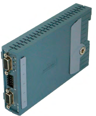
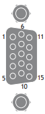
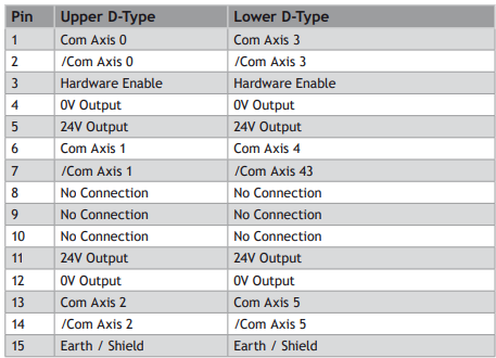
SLM CONNECTOR
TIME BASED REGISTRATION
Time based registration uses a 10MHz clock to record the time of a registration event which is then referenced to time stamps on the axis position from the digital drive network. An accurate registration position is then calculated. The 10MHz clock gives a time resolution of 100nsec. The position and speed of the axis are recorded so that the user can compensate for any fixed delays in the registration circuit.
Any time based registration input can be assigned to any Digital or Virtual axis. This makes the registration very flexible and enables multiple registration channels per axis. Each registration channel can be armed independently and assigned to an axis on the fly.
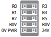
REGISTRATION CONNECTOR
R0 - R5 registration inputs (24V).
0VR common 0V return.
0V PWR Power input for SLM system.
24V Power input for SLM system.
LED FUNCTIONS
FlexAxis Interface (P874 / P879)
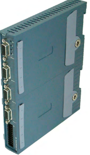
For use with Stepper, Analogue Servo & Piezo motors. The FlexAxis Interface is available in 4 axes (P879) and 8 axes (P874) versions.
Each axis provides a 16 bit analogue output, up to 8 x 24Vdc high speed registration inputs and a 6MHz encoder input. The encoder port can be configured to drive a stepper motor or an encoder simulation port, both at 2MHz.
ENCODER CONNECTOR
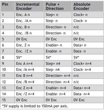
Absolute encoder is only available on axes 4-7 on the P874 and on axes 2-3 on P879.
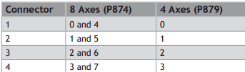
MULTIFUNCTION CONNECTOR
The 22 pin multifunction connector provides terminals for 8 registration inputs, 8 voltage outputs and 4 hardware PSWITCH outputs.
ANALOGUE OUTPUTS
8 +/-10V 16Bit analogue outputs are available for servo axis control (4 in the P879). Connect V0 as the velocity command signal for the first axis, V1 for the second axis and so on. The maximum load per axis together is 10mA.
POSITION BASED REGISTRATION
Position based registration uses the encoder signal. When the registration event occurs the encoder position is latched in hardware. The speed of the axis is also recorded so that the user can compensate for any fixed electronic delays in the registration circuit. Flexible allocation of registration inputs to axes is provided. Each axis can have a number of registration events assigned to it and the source of these events can be from any of the registration channels.
The Flex Axis module has 8 registration inputs in addition to the Z mark for each axis. The first axis has 8 registration events which can be assigned to use any of the registration inputs or its own Z mark. The remaining axes have 2 registration events which can be assigned to use any of the registration inputs or their own Z mark.
PSWITCH OUTPUTS
Inputs R4 to R7 are bi-directional and can be used as outputs for high accuracy PSWITCH operation. When used in this mode, the outputs are controlled by the position value of an axis within the same P874 / P879 module.
MULTIFUNCTION CONNECTOR PIN OUT
0V DAC common 0V return
V0 - V7 Voltage outputs
R0 - R3 24V Registration Inputs
R4/PS4 - R7/PS7 Bidirectional 24V registration In/24V: PSWITCH outputs
Inputs / 24V PSwitch outputs
0V PWR Power Input
24V Power Input
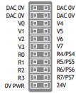
4 axis version uses voltage outputs V0 - V3 only.
LED FUNCTIONS

EtherCAT Interface (P876)
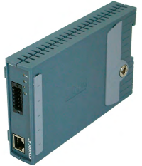
For use with EtherCAT compliant drives, this module allows control of up to 64 axes via standard shielded twisted pair (TIA/EIA-568B CAT5e or more) Ethernet cables.
Multiple EtherCAT Interface Modules can be used.
EtherCAT is an open, high performance ethernet based fieldbus system, which has been integrated into several IEC standards (IEC 61158, IEC 61784 and IEC61800). It is a high performance, deterministic protocol, with high bandwidth usage, low latency and low communication jitter. Various network topologies are supported, including line, tree or star. The EtherCAT compliant servo amplifiers from any number of vendors may be included in a network.
The module supports both the CANopen and servo drive (sercos, IEC 61491) EtherCAT profiles, along with the mailbox transfer protocol to exchange configuration, status and diagnostic information between the master and slave.
RJ45 CONNECTOR
 100 base-T Ethernet (EtherCat Master).
TIME BASED REGISTRATION
Time based registration uses a 10MHz clock to record the time of a registration event which is then referenced to time stamps on the axis position from the digital drive network. An accurate registration position is then calculated. The 10MHz clock gives a time resolution of 100nsec. The position and speed of the axis are recorded so that the user can compensate for any fixed delays in the registration circuit.
Any time based registration input can be assigned to any Digital or Virtual axis. This makes the registration very flexible and enables multiple registration channels per axis. Each registration channel can be armed independently and assigned to an axis on the fly.
REGISTRATION CONNECTOR
R0 - R7: registration inputs (24V).
R0V: registration common 0V return.
Registration inputs can be allocated to any axis by software.

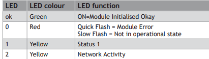
LED FUNCTIONS
Anybus-CC Module (P875)
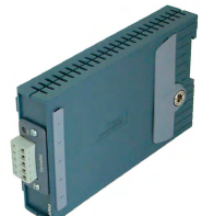
Open communications is an important aspect to any control system. This module adds support for the
Anybus CompactCom device modules.
Anybus-CC is a plug-in module supporting all major Fieldbus and Ethernet networks. Its innovative design and versatile functionality offers the Anybus-CC optimal flexibility for OEM manufacturers.
The Anybus modules can be found at: www.anybus.com
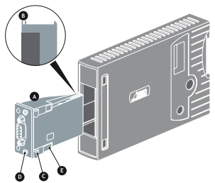
Anybus CompactCom Module shown for illustration only. Anybus CC Modules may be purchased seperately
ANYBUS MODULE FITTING
Push the Anybus® module (A) into the Trio Expansion Interface taking care to keep its base in contact with the PCB and align guide slots (B) with the connector rails inside.
Ensure that the moulded hooks (C) on the lower front edge of the Anybus® module locate under the P875 PCB at the front.
When the module is flush with the face of the Trio Expansion Interface, tighten the two “Torx”
head screws (D) to locate the two lugs (E) and secure the Anybus® module.
To remove the module, reverse this procedure.