
5. INSTALLATION
Installing the MC464
PACKAGING
The Motion Coordinator MC464 is designed to be mounted on a DIN rail or, by use of optional mounting clips, it can be screwed to a backplate.
A cast metal chassis provides mechanical stability and a reliable earth connection to aid EMC immunity.
The rugged plastic case includes ventilation holes, top and bottom, and a removable cover to access the memory battery.
EXPANDABLE DESIGN
System expansion is done by adding either single or double height modules. These are clipped to the MC464 and secured by a bolt which also acts as the earth connection between the MC464 and the module
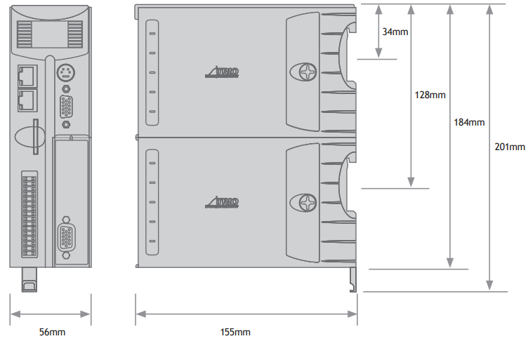
ITEMS SUPPLIED WITH THE MC464
CONNECTORS:
• 9 way D-Type plug
• Quick connect I/O connector (30 way)
PANEL MOUNTING SET:
• 2 x Mounting bracket
• 1 x M3 x 10mm Countersunk screw
• 1 x M3 x 6mm Countersunk screw
• Quick start guide
MOUNTING MC464
GENERAL
The MC464 must be mounted vertically and should not be subjected to mechanical loading. Care must be taken to ensure that there is a free flow of air vertically around the MC464.
DIN RAIL
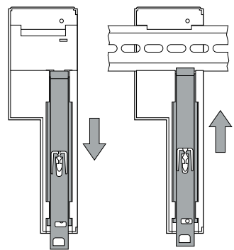
Pull down the clip to allow the MC464 to be mounted on a single DIN rail. Push up the clip to lock it to the rail.
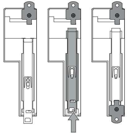
Mounting Clips
Remove the 2 mounting clips from their packaging and insert one at the top rear of the case, by fitting the small tab into the rectangular slot and fix with the M3 x 6mm screw provided.
The second clip fits to the bottom of the case rear. Line up the DIN rail lever with the hole and slot in the metal chassis, fit the clip into the slot and fix it with the M3 x 10mm screw.
ENVIRONMENTAL CONSIDERATIONS
The MC464 should not be handled whilst the 24 Volt power is connected.
ENSURE THAT THE AREA AROUND THE VENTILATION HOLES AT THE TOP AND BOTTOM OF THE MC464 AND ANY ADDITIONAL MODULES ARE KEPT CLEAR. AVOID VIOLENT SHOCKS TO, OF VIBRATION OF, THE MC464, SYSTEM AND MODULES WHILST IN USE OR STORAGE.
IP RATING: IP 20
The MC464 and add-on modules are protected against solid objects intruding into the case and against humidity levels that do not induce condensation to occur.
Installing the MC4N
PACKAGING
The Motion Coordinator MC4N is designed to be mounted using the 2 mounting holes located on the backplate.
A cast metal chassis provides superb mechanical stability and a dedicated earth connection point to aid EMC immunity.
The rugged plastic case has conveniently placed access ports for the I/O, encoder inputs, pulse outputs, EtherCAT port, Ethernet and serial connections. A slot is provided for the optional Micro SD card.
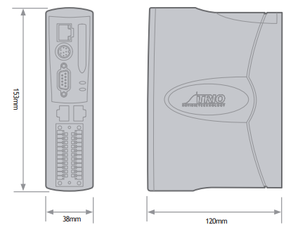
ITEMS SUPPLIED WITH THE MC4N
CONNECTORS
• 1 x 9 way D-Type plug and shell
• 1 x 5 way quick dis-connect screw terminal block
• 2 x 12 way quick dis-connect screw I/O connector
• Quick start guide
MOUNTING MC4N
GENERAL
The MC4N must be mounted vertically and should not be subjected to mechanical loading. Care must be taken to ensure that there is a free flow of air vertically around the MCN.
SCREW MOUNTING
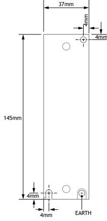
Drill and tap 2 mounting holes using the dimensions shown below. Use 2 x M4 pan-head screws, (not supplied) of a suitable length, to fix the MC4N to the panel. Screw the lower screw into the panel, leaving the screw head between 4 and 6 mm above the panel surface. Slide the MC4N down on to the screw and insert the upper screw. Tighten both screws.
ENVIRONMENTAL CONSIDERATIONS
The MC4N should not be handled whilst the 24 Volt power is connected.
ENSURE THAT THE AREA AROUND THE TOP AND BOTTOM OF THE MC4N AND ANY ADDITIONAL I/O MODULES IS KEPT CLEAR. AVOID VIOLENT SHOCKS TO, OF VIBRATION OF, THE MC4N SYSTEM AND MODULES WHILST IN USE OR STORAGE.
IP RATING: IP 20
The MC4N is protected against solid objects intruding into the case and against humidity levels that do not induce condensation to occur.
Instaling the MC405 / MC403
PACKAGING
The Motion Coordinator MC405 / MC403 is designed to be mounted on a DIN rail or optionally, using the 3 mounting holes, it can be screwed to a back-plate.
A cast metal chassis provides superb mechanical stability and a dedicated earth connection point to aid EMC immunity.
The rugged plastic case has conveniently placed access ports for the I/O, encoder inputs, pulse outputs, Ethernet and serial connections. A slot is provided for the optional Micro SD card.
ITEMS SUPPLIED WITH THE MC405 / MC403
CONNECTORS
• 3 or 5 x 9 way D-Type plug and shell
• 1 x 5 way quick dis-connect screw terminal block
• 8 way and 14 way quick dis-connect screw terminal block (MC403)
• 2 x 10 way and 1 x 16 way quick dis-connect screw terminal block (MC405)
• Quick start guide
MOUNTING MC405 / MC403
GENERAL
The MC405 / MC403 must be mounted vertically and should not be subjected to mechanical loading. Care must be taken to ensure that there is a free flow of air vertically around the MC405/MC403.
DIN RAIL
Pull down the clip to allow the MC405 / MC403 to be mounted on a single DIN rail. Release the spring-loaded clip to lock it to the rail.
SCREW MOUNTING
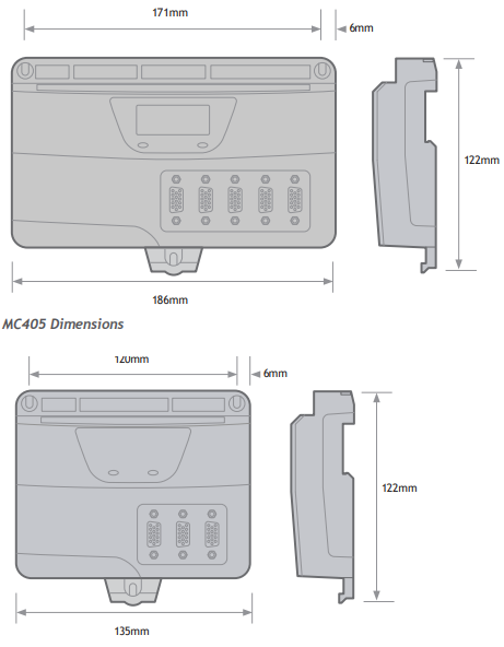
Drill and tap 3 mounting holes using the dimensions shown below. Use 3 x M4 pan-head screws, (not supplied) of a suitable length, to fix the MC405 / MC403 to the panel. Screw the upper 2 screws into the panel, leaving the screw head between 4 and 6 mm above the panel surface. Slide the MC405/MC403 up on to the 2 screws and insert the remaining lower screw. Tighten all 3 screws.
ENVIRONMENTAL CONSIDERATIONS
The MC403 / MC405 should not be handled whilst the 24 Volt power is connected.
ENSURE THAT THE AREA AROUND THE TOP AND BOTTOM OF THE MC405 / MC403 AND ANY ADDITIONAL I/O MODULES IS KEPT CLEAR. AVOID VIOLENT SHOCKS TO, OF VIBRATION OF, THE MC405 / MC403, SYSTEM AND MODULES WHILST IN USE OR STORAGE.
IP RATING: IP 20
The MC405 / MC403 are protected against solid objects intruding into the case and against humidity levels that do not induce condensation to occur.
Installing the CAN I/O Modules
PACKAGING
The CAN I/O modules are designed to be mounted on a DIN rail.
The rugged plastic case includes ventilation holes, top and bottom.
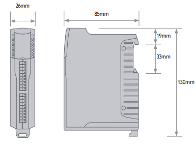
The dimensions are shown below.
ITEMS SUPPLIED WITH CAN I/O MODULES
• 5 way CAN connector
• 2x 10 way I/O connectors
• 2x 120 Ohm terminating resistors
• Quick start guide
MOUNTING CAN I/O MODULES
The CAN I/O modules should be mounted vertically and should not be subjected to mechanical loading.
Care must be taken to ensure that there is a free flow of air vertically around the CAN I/O module.
To mount pull down the sprung loaded clip, slot over the DIN rail and release the clip to lock the module to the rail.
ENVIRONMENTAL CONSIDERATIONS
The CAN I/O should not be handled whilst the 24 Volt power is connected.
ENSURE THAT THE AREA AROUND THE VENTILATION HOLES AT THE TOP AND BOTTOM OF THE CAN I/O ARE KEPT CLEAR. AVOID VIOLENT SHOCKS TO, OF VIBRATION OF, THE CAN I/O MODULES WHILST IN USE OR STORAGE.
IP RATING: IP 20
BUS WIRING
The CAN 16-I/O Modules and the Motion Coordinator are connected together on a CAN network running at 500kHz. The network is of a linear bus topology. That is the devices are daisy-chained together with spurs from the chain. The total length is allowed to be up to 100m, with drop lines or spurs of up to 6m in length. At both ends of the network, 120 Ohm terminating resistors
are required between the CAN_H and CAN_L connections. The resistor should be 1/4 watt, 1% metal film.
The cable required consists of:
• Blue/White 24AWG data twisted pair
• Red/Black 22AWG DC power twisted pair
• Screen
A suitable type is Belden 3084A.
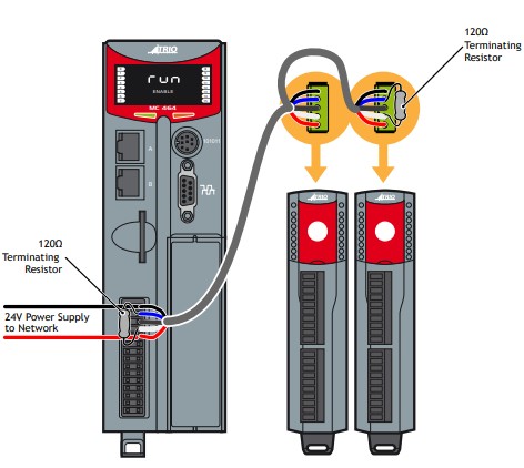
The CAN 16-I/O modules are powered from the network. The 24 Volts supply for the network must be externally connected. The Motion Coordinator does NOT provide the network power. In many installations the power supply for the Motion Coordinator will also provide the network power.
It is recommended that you use a separate power supply from that used to power the I/O to power the network as switching noise from the I/O devices may be carried into the network.