4. STANDARD IEC 61131-3 COMMANDS
Introduction to the Standard IEC Language
Below are the available programming languages of the IEC61131-3 standard:
SFC: Sequential Function Chart
FBD: Function Block Diagram
LD: Ladder Diagram
ST: Structured Text
Use of ST instructions in graphic languages
You have to select a language for each program or User Defined Function Block of the application.
Sequential Function Chart (SFC)
The SFC language is a state diagram. Graphical steps are used to represent stable states, and transitions describe the conditions and events that lead to a change of state. Using SFC highly simplifies the programming of sequential operations as it saves a lot of variables and tests just for maintaining the program context.
YOU MUST NOT USE SFC AS A DECISION DIAGRAM. USING A STEP AS A POINT OF DECISION AND TRANSITIONS AS CONDITIONS IN AN ALGORITHM SHOULD NEVER APPEAR IN A SFC CHART. USING SFC AS A DECISION LANGUAGE LEADS TO POOR PERFORMANCE AND COMPLICATE CHARTS. ST MUST BE PREFERRED WHEN PROGRAMMING A DECISION ALGORITHM THAT HAS NO SENSE IN TERM OF “PROGRAM STATE”.
Below are basic components of an SFC chart:
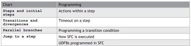
The workbench fully supports SFC programming with several hierarchical levels of charts: i.e. a chart that controls another chart. Working with a hierarchy of SFC charts is an easy and powerful way for managing complex sequences and saves performances at run time. Refer to the following sections for further details:
Hierarchy of SFC programs
Controlling a SFC child program
Actions in a SFC step
Each step has a list of action blocks, that are instructions to be executed according to the activity of the step. Actions can be simple boolean or SFC actions, that consists in assigning a boolean variable or control a child SFC program using the step activity, or action blocks entered using another language (FBD, LD or ST).
RUNTIME CHECK
Below are the possible syntaxes you can use within an SFC step to perform runtime safety checks:

SIMPLE BOOLEAN ACTIONS
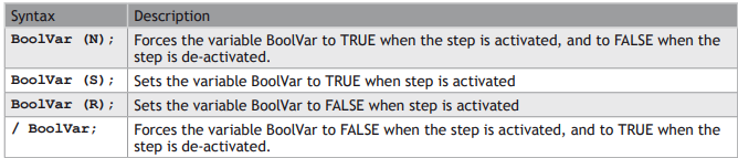
Below are the possible syntaxes you can use within an SFC step to perform a simple boolean action:
ALARMS
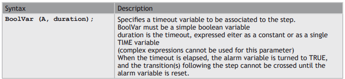
The following syntax enables you to manage timeout alarm variables:
SIMPLE SFC ACTIONS
Below are the possible syntaxes you can use within an SFC step to control a child SFC program:


PROGRAMMED ACTION BLOCKS
Programs in other languages (FBD, LD or ST) can be entered to describe an SFC step action. There are three main types of programmed action blocks, that correspond to the following identifiers:

The workbench provides you templates for entering P1, N and P0 action blocks in either ST, LD or FBD language. Alternatively, you can insert action blocks programmed in ST language directly in the list of simple actions, using the following syntax:
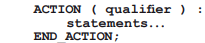
Where qualifier is P1, 0 or P0.
CHECK TIMEOUT ON A SFC STEP
The system can check timeout on any SFC step activity duration. For that you need to enter the following instruction in the main “Action” list of the step:

Where:
timeout is a time constant or a time variable specifying the timeout duration. errString is a string constant or a string variable specifying the error message to be output.
At runtime, each time the activation time of the step becomes greater than the specified timeout, the error string is sent to the Workbench and displayed in the Log window.
SENDING LOG MESSAGE STRINGS TO THE LOG WINDOW REQUIRES THE RUNTIME TO BE CONNECTED THROUGH ETHERNET, AND THAT YOUR T5 RUNTIME SYSTEM SUPPORTS PLAIN TEXT TRACE MESSAGES.
You can also put this statement within a #ifdef __DEBUG test so that timeout checking is enabled only in debug mode.
Alternatively, if you need to make more specific handling of timeouts, you can enter the following ST program in the “N” action block of the step:
if GSn.T > timeout then /* ‘n’ is the number of the step */ ...statements... end_if;
CONDITION OF A SFC TRANSITION
Each SFC transitions must have a boolean condition that indicates if the transition can be crossed. The condition is a boolean expression that can be programmed either in ST or LD language.
In ST language, enter a boolean expression. In can be a complex expression including function calls and parenthesis.
EXAMPLE
bForce AND (bAlarm OR min (iLevel, 1) <> 1)
In LD language, the condition is represented by a single rung. The coil at the end of the rung represents the transition and should have no symbol attached.
EXAMPLE
CONTROLLING A SFC CHILD PROGRAM
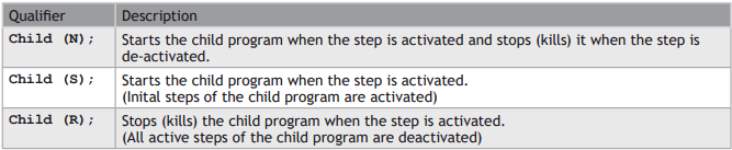
Controlling a child program may be simply achieved by specifying the name of the child program as an action block in a step of its parent program. Below are possible qualifiers that can be applied to an action block for handling a child program:
Alternatively, you can use the following statements in an action block programmed in ST language. In the following table, prog represents the name of the child program:
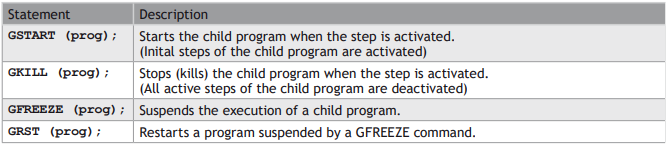
You can also use the “GSTATUS” function in expressions. This function returns the current state of a child SFC program:

When a child program is started by its parent program, it keeps the inactive status until it is executed (further in the cycle). If you start a child program in a SFC chart, GSTATUS will return 1 (active) on the next cycle.
Hierarchy of SFC programs
Each SFC program may have one or more “child programs”. Child programs are written in SFC and are started (launched) or stopped (killed) in the actions of the father program. A child program may also have children. The number of hierarchy levels should not exceed 19.
When a child program is stopped, its children are also implicitly stopped.
When a child program is started, it must excplicitly in its actions start its children.
A child program is controlled (started or stopped) from the action blocks of its parent program. Designing a child program is a simple way to program an action block in SFC language.
Using child programs is very useful for designing a complex process and separate operations due to different aspects of the process. For instance, it is common to manage the execution modes in a parent program and to handle details of the process operations in child programs.
JUMP TO A SFC STEP
Jump symbols can be used in SFC charts to represent a link from a transition to a step without actually drawing it. The jump is represented by an arrow identified with the number of the target step.
To change the number of a step, transition or jump, select it and hit Ctrl+ENTER keys.
You cannot insert a jump to a transition as it may lead to a non explicit convergence of parallel branches (several steps leading to the same transition) and generally leads to mistakes due to a bad understanding of the chart.
SFC PARALLEL BRANCHES
Parallel branches are used in SFC charts to represent parallel operations. Parallel branches occur when more than several steps are connected after the same transition. Parallel branches are drawn as double horizontal lines:
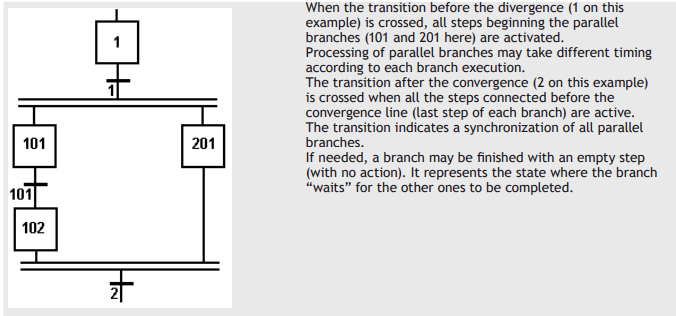
You must take care of the following rules when drawing parallel lines in order to avoid dead locks in the execution of the program:
• All branches must be connected to the divergence and the convergence.
• An element of a branch must not be connected to an element outside the divergence.
SFC execution at run time
SFC programs are executed sequentially within a target cycle, according to the order defined when entering programs in the hierarchy tree. A parent SFC program is executed before its children. This implies that when a parent starts or stops a child, the corresponding actions in the child program are performed during the same cycle.
Within a chart, all valid transitions are evaluated first, and then actions of active steps are performed. The chart is evaluated from the left to the right and from the top to the bottom.
EXAMPLE
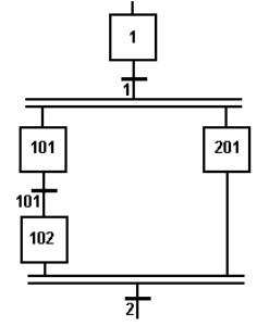
Execution order:
• Evaluate transitions:
• 1, 101, 2
• Manage steps:
• 1, 101, 201, 102
In case of a divergence, all conditions are considered as exclusive, according to a left to right priority order. It means that a transition is considered as FALSE if at least one of the transitions connected to the same divergence on its left side is TRUE.
The initial steps define the initial status of the program when it is started. All top level (main) programs are started when the application starts. Child programs are explicitly started from action blocks within the parent programs.
The evaluation of transitions leads to changes of active steps, according to the following rules:
A transition is crossed if:
• its condition is TRUE.
• and if all steps linked to the top of the transition (before) are active.
When a transition is crossed:
• all steps linked to the top of the transition (before) are de-activated.
• all steps linked to the bottom of the transition (after) are activated.
EXECUTION OF SFC WITHIN THE T5 TARGET IS SAMPLED ACCORDING TO THE TARGET CYCLES. WHEN A TRANSITION IS CROSSED WITHIN A CYCLE, THE FOLLOWING STEPS ARE ACTIVATED, AND THE EVALUATION OF THE CHART WILL CONTINUE ON THE NEXT CYCLE. IF SEVERAL CONSECUTIVE TRANSITIONS ARE TRUE WITHIN A BRANCH, ONLY ONE OF THEM IS CROSSED WITHIN ONE TARGET CYCLE.
THIS SECTION DESCRIBES THE EXECUTION MODEL OF A STANDARD T5 TARGET. SFC EXECUTION RULES MAY DIFFER FOR OTHER TARGET SYSTEMS. PLEASE REFER TO OEM INSTRUCTIONS FOR FURTHER DETAILS ABOUT SFC EXECUTION AT RUN TIME.
SOME RUN-TIME SYSTEMS MAY NOT SUPPORT EXCLUSIVITY OF THE TRANSITIONS WITHIN A DIVERGENCE. PLEASE REFER TO OEM INSTRUCTIONS FOR FURTHER INFORMATION ABOUT SFC SUPPORT.
SFC STEPS
A step represents a stable state. It is drawn as a square box in the SFC chart. Each must step of a program is identified by a unique number. At run time, a step can be either active or inactive according to the state of the program.
To change the number of a step, transition or jump, select it and hit Ctrl+ENTER keys.
All actions linked to the steps are executed according to the activity of the step.
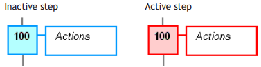
In conditions and actions of the SFC program, you can test the step activity by specifying its name (“GS” plus the step number) followed by “.X”.
EXAMPLE
GS100.X Is TRUE if step 100 is active. (Expression has the BOOL data type).
You can also test the activity time of a step, by specifying the step name followed by “.T”. It is the time elapsed since the activation of the step. When the step is de-activated, this time remains unchanged. It will be reset to 0 on the next step activation.
EXAMPLE
GS100.T Is the time elapsed since step 100 was activated. (Expression has the TIME data type).
INITIAL STEPS
Initial steps represent the initial situation of the chart when the program is started. There must be at least one initial step in each SFC chart. An initial step is marked with a double line:
SFC TRANSITIONS
Transitions represent a condition that changes the program activity from a step to another.
To change the number of a step, transition or jump, select it and hit Ctrl+ENTER keys.
The transition is marked by a small horizontal line that crosses a link drawn between the two steps:
Each transition is identified by a unique number in the SFC program.
Each transition must be completed with a boolean condition that indicates if the
transition can be crossed. The condition is a BOOL expression.
In order to simplify the chart and reduce the number of drawn links, you can specify
the activity flag of a step (GSnnn.X) in the condition of the transition.
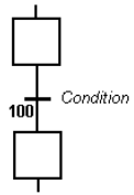
Transitions define the dynamic behaviour of the SFC chart, according to the following rules:
A transition in crossed if:
• its condition is TRUE.
• and if all steps linked to the top of the transition (before) are active.
When a transition is crossed:
• all steps linked to the top of the transition (before) are de-activated.
• all steps linked to the bottom of the transition (after) are activated.
DIVERGENCES
It is possible to link a step to several transitions and thus create a divergence. The divergence is represented by a horizontal line. Transitions after the divergence represent several possible changes in the situation of the program.
All conditions are considered as exclusive, according to a left to right priority order. It means that a transition is considered as FALSE if at least one of the transitions connected to the same divergence on its left side is TRUE.
EXAMPLE
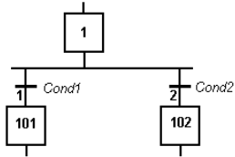
Transition 1 is crossed if:
step 1 is active
and Cond1 is TRUE
Transition 2 is crossed if:
step 1 is active
and Cond2 is TRUE
and Cond1 is FALSE
SOME RUN-TIME SYSTEMS MAY NOT SUPPORT EXCLUSIVITY OF THE TRANSITIONS WITHIN A DIVERGENCE. PLEASE REFER TO OEM INSTRUCTIONS FOR FURTHER INFORMATION ABOUT SFC SUPPORT.
User Defined Function Blocks programmed in SFC
The Workbench enables you to create User Defined Function Blocks (UDFBs) programmed with SFC language.
This section details specific features related to such function blocks.
The execution of UDFBs written in SFC requires a runtime system version SR7-1 or later.
DECLARATION
From the Workspace contextual menu, run the Insert New Program command. Then specify a valid name for the function block. Select “SFC” language and “UDFB” execution style.
PARAMETERS
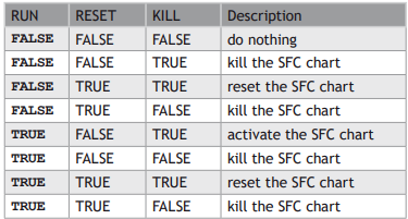
When a UDFB programmed in SFC is created, the Workbench automatically declares 3 special inputs to the block:
RUN: The SFC state machine is not activated when this input is FALSE.
RESET: The SFC chart is reset to its initial situation when this input is TRUE.
KILL: Any active step of the SFC chart is deactivated when this input is TRUE.
You can freely add other input and output variables to the UDFB. You can also remove any of the automatically created input if not needed. If the RUN input is removed, then it is considered as always
TRUE. If RESET or KILL inputs are removed, then they are considered as always FALSE.
Below is the truth table showing priorities among special input:
STEPS
All steps inserted in the SFC chart of the UDFB are automatically declared as local instances of special reserved function blocks with the local variables of the UDFBs. The following FB types are used:
isfcSTEP : a normal step
isfcINITSTEP : an initial step
The editor takes care of updating the list of declared step instances. You should never remove, rename or change them in the variable editor. All steps are named with GS followed by their number.
EXECUTION
The SFC chart is operated only when the UDFB is called by its parent program.
If the RESET input is TRUE, the SFC chart is reset to its initial situation. If the KILL input is TRUE, any active step of the SFC chart is deactivated.
When the RUN input is TRUE and KILL/RESET are FALSE, the SFC chart is operated in the same way as for other SFC programs:
• Check valid transitions and evaluate related conditions.
• Cross TRUE valid transitions.
• Execute relevant actions of the active steps.
In a UDFB programmed in SFC, you cannot use SFC actions to pilot a “child SFC program”. This feature is reserved for SFC programs only. Instead, a UDFB programmed in SFC can pilot from its actions another UDFB programmed in SFC.
Function Block Diagram (FBD)
A Function Block Diagram is a data flow between constant expressions or variables and operations represented by rectangular blocks. Operations can be basic operations, function calls, or function block calls.
USE OF ST INSTRUCTIONS IN GRAPHIC LANGUAGES
The name of the operation or function, or the type of function block is written within the block rectangle.
In case of a function block call, the name of the called instance must be written upon the block rectangle, such as in the example below:
EXAMPLE
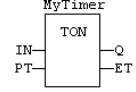
The data flow may represent values of any data type. All connections must be from input and outputs points having the same data type. In case of a boolean connection, you can use a connection link terminated by a small circle, that indicates a boolean negation of the data flow.
EXAMPLE
Use of a negated link: Q is IN1 AND NOT IN2!

The data flow must be understood from the left to the right and from the top to the bottom. It is possible to use labels and jumps to change the default data flow execution.
LD SYMBOLS
LD symbols may also be entered in FBD diagrams and linked to FBD objects. Refer to the following sections for further information about components of the LD language:
Contacts, Coils, Power Rails
Special vertical lines are available in FBD language for representing the merging of LD parallel lines. Such vertical lines represent a OR operation between the connected inputs. Below is an example of an OR vertical line used in a FBD diagram:
Ladder Diagram (LD)
A Ladder Diagram is a list of rungs. Each rung represents a boolean data flow from a power rail on the left to a power rail on the right. The left power rail represents the TRUE state. The data flow must be understood from the left to the right. Each symbol connected to the rung either changes the rung state or performs an operation. Below are possible graphic items to be entered in LD diagrams:
Power Rails
Contacts and Coils
Operations, Functions and Function blocks, represented by rectangular blocks
Labels and Jumps
Use of ST instructions in graphic languages
USE OF THE EN INPUT AND THE ENO OUTPUT FOR BLOCKS
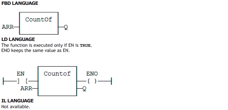
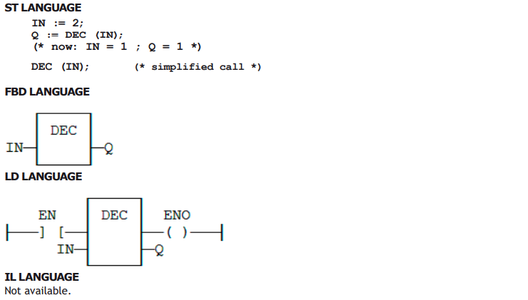
The rung state in a LD diagram is always boolean. Blocks are connected to the rung with their first input and output. This implies that special EN and ENO input and output are added to the block if its first input or output is not boolean.
The EN input is a condition. It means that the operation represented by the block is not performed if the rung state (EN) is FALSE. The ENO output always represents the sane status as the EN input: the rung state is not modified by a block having an ENO output.
Below is the example of the XOR block, having boolean inputs and outputs, and requiring no EN or ENO pin:
First input is the rung. The rung ist the output.
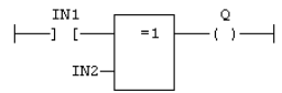
Below is the example of the > (greater than) block, having non boolean inputs and a boolean output. This block has an EN input in LD language:
The comparison is executed only if EN is TRUE.
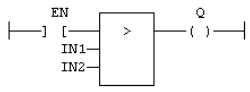
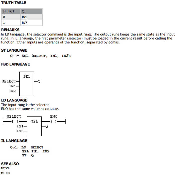
Below is the example of the SEL function, having a first boolean input, but an integer output. This block has an ENO output in LD language:
The input rung is the selector.
ENO has the same value as SELECT.
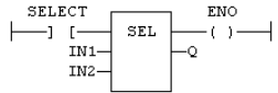
Finally, below is the example of an addition, having only numerical arguments. This block has both EN and ENO pins in LD language:
The addition is executed only if EN is TRUE.
ENO is equal to EN.
Contacts
Contacts are basic graphic elements of the LD language. A contact is associated to a boolean variable written upon its graphic symbol. A contact sets the state of the rung on its right side, according to the value of the associated variable and the rung state on its left side.
Below are the possible contact symbols and how they change the rung state:
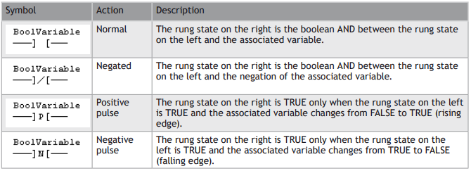
When a contact or a coil is selected, You can press the SPACE bar to change its type (normal, negated,
pulse...).
Two serial normal contacts represent an AND operation.
Two contacts in parallel represent an OR operation.
SEE ALSO
Coils
Power Rails
Coils
Coils are basic graphic elements of the LD language. A coil is associated to a boolean variable written upon its graphic symbol. A coil performs a change of the associated variable according to the rung state on its left side.
Below are the possible coil symbols and how they change the rung state:
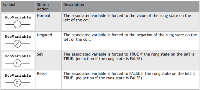
When a contact or a coil is selected. You can press the SPACE bar to change its type (normal, negated, pulse...).
EVEN THOUGH COILS ARE COMMONLY CONNECTED TO A POWER RAIL ON THE RIGHT, THE RUNG MAY BE CONTINUED AFTER A COIL. THE RUNG STATE IS NEVER CHANGED BY A COIL SYMBOL.
SEE ALSO
Contacts
Power Rails
Power Rails
Vertical power rails are used in LD language for representing the limits of a rung.
The power rail on the left represents the TRUE value and initiates the rung state. The power rail on the right receives connections from the coils and has no influence on the execution of the program.
Power rails can also be used in FBD language. Only boolean objects can be connected to left and right power rails.
SEE ALSO
Contacts
Coils
Structured Text (ST)
ST is a structured literal programming language. A ST program is a list of statements. Each statement describes an action and must end with a semicolon (“;”).
The presentation of the text has no meaning for a ST program. You can insert blank characters and line breaks where you want in the program text.
COMMENTS
Comment texts can be entered anywhere in a ST program. Comment texts have no meaning for the execution of the program. A comment text must begin with “(*” and end with “*)”. Comments can be entered on several lines (i.e. a comment text may include line breaks). Comment texts cannot be nested.
EXPRESSIONS
Each statement describes an action and may include evaluation of complex expressions. An expression is evaluated:
From the left to the right.
• According to the default priority order of operators.
• The default priority can be changed using parentheses.
Arguments of an expression can be:
• Declared variables
• Constant expressions
• Function calls
STATEMENTS
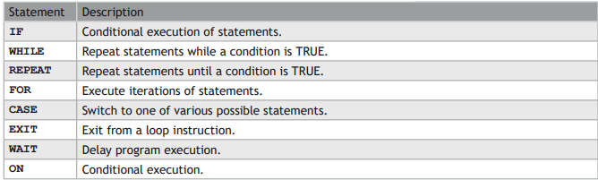
Below are available basic statements that can be entered in a ST program:
• assignment
• function block calling
Below are the available conditional statements in ST language:
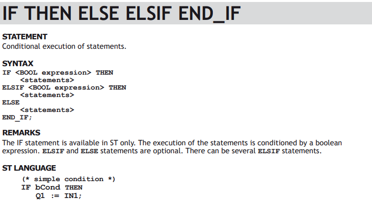
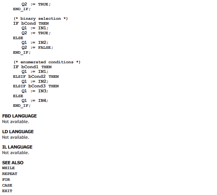
• IF / THEN / ELSE (simple binary switch).
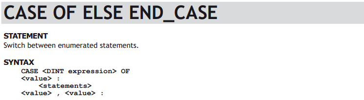
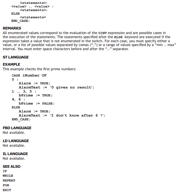
• CASE (enumerated switch).
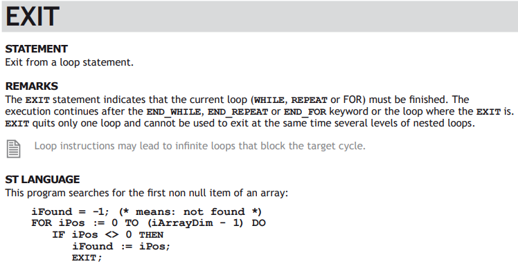
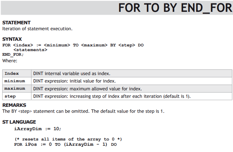
Below are the available statements for describing loops in ST language:
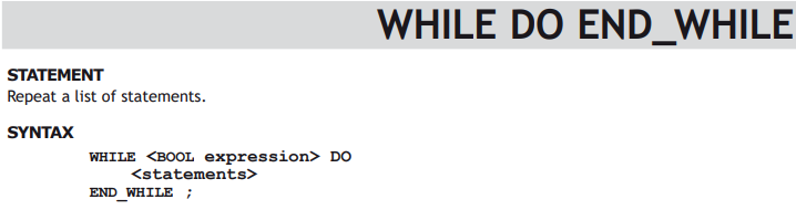
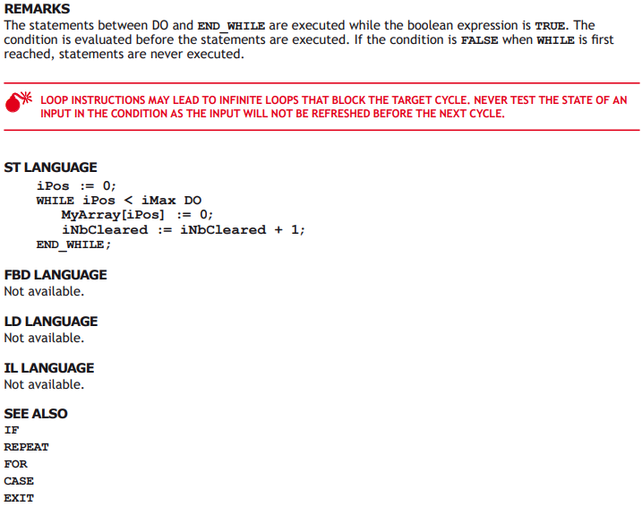
• WHILE (with test on loop entry).
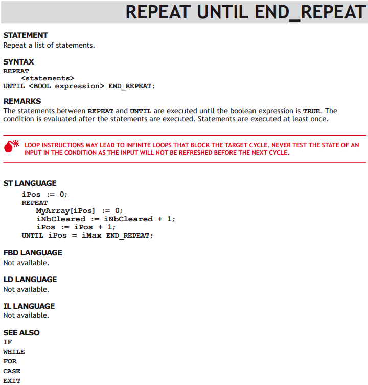
• REPEAT (with test on loop exit).
FOR (enumeration).
Use of ST expressions in a graphic language
The workbench enables any complex ST expression to be associated with a graphic element in either LD or FBD language. This feature makes possible to simplify LD and FBD diagrams when some trivial calculation has to be entered. It also enables you to use graphic features for representing a main algorithm as text is used for details of implementation.
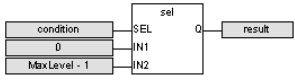
Expression must be written in ST language. An expression is anything you can imagine between parenthesis in a ST program. Obviously the ST expression must fit the data type required by the diagram (e.g. an expression put on a contact must be boolean).
FBD LANGUAGE
A complex ST expression can be entered in any variable box of a FBD diagram, if the box is not connected on its input.
EXAMPLE
LD LANGUAGE
A complex ST expression can be entered on any kind of contact, and on any input of a function or function block.
Program organization units
An application is a list of programs. Programs are executed sequentially within the target cycle, according to the following model:
Begin cycle
| exchange I/Os
| execute first program
| ...
| execute last program
| wait for cycle time to elapse
End Cycle
Programs are executed according to the order defined by the user. All SFC programs must be grouped (it is not possible to insert a program in FBD, LD or ST in between two SFC programs). The number of programs in an application is limited to 32767. Each program is entered using a language chosen when the program is created.
Possible languages are:
• Sequential Function Chart (SFC),
• Function Block Diagram (FBD),
• Ladder Diagram (LD),
• Structured Text (ST)
Programs must have unique names. The name cannot be a reserved keyword of the programming languages and cannot have the same name as a standard or “C” function or function block. A program should not have the same name as a declared variable. The name of a program should begin by a letter or an underscore (“_”) mark, followed by letters, digits or underscore marks. It is not allowed to put two consecutive underscores within a name. Naming is case insensitive. Two names with different cases are considered as the same.
CHILD SFC PROGRAMS
You can define a hierarchy of SFC programs, entered as a tree in the list of programs. A child program is controlled within action blocks of the parent SFC program.
USER DEFINED FUNCTION BLOCKS
The list of programs may be completed by User Defined Function Blocks (UDFBs). UDFBs are described using SFC, FBD, LD or ST language, and can be used as other function blocks in the programs of the application.
Input and output parameters plus private variables of a UDFB are declared in the variable editor as local variables of the UDFB.
There is no restriction using any operation in a UDFB. A UDFB can call standard functions and function blocks.
A UDFB can call another UDFB. The called UDFB must be declared before the calling one in the program list.
Each time a UDFB is instantiated, its private variables are duplicated for the declared instance. The code of the UDFB is duplicated on each call in parent programs. This leads to higher performances at run time, but consumes code space. It is advised recommended to package small algorithms in UDFBs. Large parts of code should be managed in programs.
A UDFB cannot have more than 32 input parameters or 32 output parameters.
SUB-PROGRAMS
The list of programs may be completed by Sub-programs. Sub-programs are described using FBD, LD, ST or IL language, and can be called by the programs of the application. Input and output parameters plus local variables of a sub-program are declared in the variable editor as local variables of the sub-program.
A sub-program may call another sub-program or a UDFB.
Unlike UDFB, local variables of a sub program are not instantiated. This means that the sub-program always work on the same set of local variables. Local variables of a sub-program keep their value among various calls. The code of a sub-program is not duplicated when called several times by parent programs.
A sub-program cannot have more than 32 input parameters or 32 output parameters.
Data types
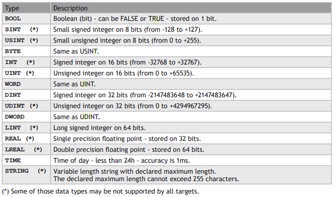
BASIC DATA TYPES
STRUCTURES
A structure is a complex data type defined as a set of members. Members of a structure may have various data types. A member of a structure may have dimensions or may be an instance of another structure.
When a structure is defined, it may be used as other data types to declare variables.
Members of a structure may have an initial value. In that case, corresponding members of all declared variable having this structure type will be initialized with the initial value of the member.
For specifying a member of a structured variable in languages, use the following notation:
VariableName.MemberName
ENUMERATED DATA TYPES
You can define some new data types that are enumaration of named values. For example:
type: LIGHT
values: GREEN, ORANGE, RED
Then in programs, you can use one of the enumerated values, prefixed by the type name:
Light1 := LIGHT#RED;
Variables having enumerated data types can only be used for assignment, comparison, and SEL/MUX
functions.
“BIT FIELD” DATA TYPES
You can define new data types derived from integer data types, that have some readable names for some of their bits. Thus you can use VarName.BitName notations in programs. Such data types cannot be derived from the LINT type.
Variables
All variables used in programs must be first declared in the variable editor. Each variable belongs to a group and is must be identified by a unique name within its group.
GROUPS
A group is a set of variables. A group either refers to a physical class of variables, or identifies the variables local to a program or user defined function block. Below are the possible groups:
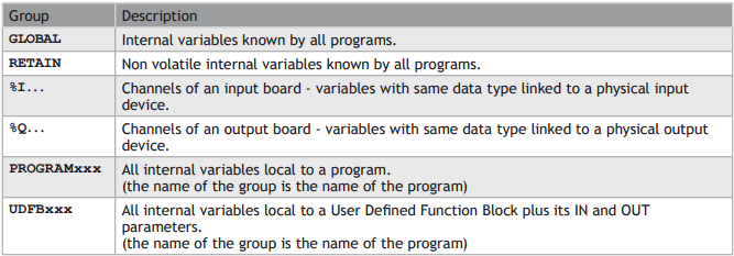
DATA TYPE AND DIMENSION
Each variable must have a valid data type. It can be either a basic data type or a function block. In that case the variable is an instance of the function block. Physical I/Os must have a basic data type. Instances of function blocks can refer either to a standard or “C” embedded block, or to a User Defined Function Block.
If the selected data type is STRING, you must specify a maximum length, that cannot exceed 255 characters.
Refer to the list of available data types for more information. Refer to the section describing function blocks for further information about how to use a function instance.
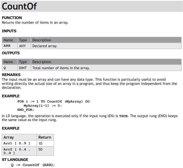
Additionally, you can specify dimension(s) for an internal variable, in order to declare an array. Arrays have at most 3 dimensions. All indexes are 0 based. For instance, in case of single dimension array, the first element is always identified by ArrayName[0]. The total number of items in an array (merging all dimensions) cannot exceed 65535.
NAMING A VARIABLE
A variable must be identified by a unique name within its parent group. The variable name cannot be a reserved keyword of the programming languages and cannot have the same name as a standard or “C” function or function block. A variable should not have the same name as a program or a user defined function block.
The name of a variable should begin by a letter or an underscore (“_”) mark, followed by letters, digits or underscore marks. It is not allowed to put two consecutive underscores within a variable name. Naming is case insensitive. Two names with different cases are considered as the same.
NAMING PHYSICAL I/OS
Each I/O channel has a predefined symbol that reflects its physical location. This symbol begins with %I for an input and %Q for an output, followed by a letter identifying the physical size of the data. Then comes the location of the board, expressed on 1 or two numbers, and finally the 0 based index of the channel within the board. All numbers are separated by dots. Below are the possible prefixes for IO symbols:
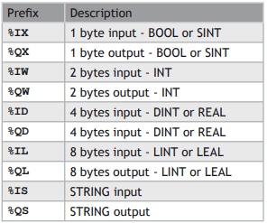
Additionally, you can give an alias (a readable name) to each I/O channel. In that case, either the “%” name or the alias can be used in programs with no difference. The alias must fit to the same rules as a variable name.
ATTRIBUTES OF A VARIABLE
Physical I/Os are marked as either Input or Output. Inputs are read-only variables. For each internal variable, you can select the Read Only.
Parameters of User Defined Function Blocks and sub-programs are marked as either IN or OUT.
PARAMETERS OF SUB-PROGRAMS AND UDFBS
Sub-programs and UDFBs may have parameters on input or ou output. Output parameters cannot be arrays of data structures but only single data. When an array is passed as an inupt parameter to a UDFB, it is considered as INOUT so the UDFB can read or write in it. The support of complex data types for input parameters may depend on selected compiling options.
Arrays
You can specify dimension(s) for internal variables, in order to declare arrays. All indexes are 0 based. For instance, in case of single dimension array, the first element is always identified by ArrayName[0].
To declare an array, enter its dimension in the corresponding column of the variable editor. For a multidimension array, enter dimensions separated by comas (ex: 2,10,4).
USE IN ST AND IL LANGUAGES
To specify an item of an array in ST language, enter the mane of the array followed by the index(es) entered between “[“ and “]” characters. For multi-dimension arrays, enter indexes separated by comas. Indexes may be either constant or complex expressions.
EXAMPLE
TheArray[1,7] := value;
result := SingleArray[i + 2];
USE IN FBD AND LD LANGUAGES
In graphical languages, the following blocks are available for managing array elements:
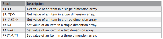
For get blocks, the first input is the array and the output is the value of the item. Other inputs are indexes in the array.
For put blocks, the first input is the forced value and the second input is the array. Other inputs are indexes in the array.
Arrays have at most 3 dimensions.
All indexes are 0 based.
The total number of items in an array (merging all dimensions) cannot exceed 65535.
Constant Expressions
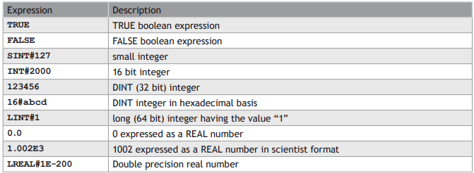
Constant expressions can be used in all languages for assigning a variable with a value. All constant expressions have a well defined data type according to their semantics. If you program an operation between variables and constant expressions having inconsistent data types, it will lead to syntactic errors when the program is compiled. Below are the syntactic rules for constant expressions according to possible data types:
BOOL: BOOLEAN
There are only two possible boolean constant expressions. They are reserved keywords TRUE and FALSE.
SINT: SMALL (8 BIT) INTEGER
Small integer constant expressions are valid integer values (between -128 and 127) and must be prefixed with SINT#. All integer expressions having no prefix are considered as DINT integers.
USINT / BYTE: UNSIGNED 8 BIT INTEGER
Unsigned small integer constant expressions are valid integer values (between 0 and 255) and must be prefixed with USINT#. All integer expressions having no prefix are considered as DINT integers.
INT: 16 BIT INTEGER
16 bit integer constant expressions are valid integer values (between -32768 and 32767) and must be prefixed with INT#. All integer expressions having no prefix are considered as DINT integers.
UINT / WORD: UNSIGNED 16 BIT INTEGER
Unsigned 16 bit integer constant expressions are valid integer values (between 0 and 255) and must be prefixed with UINT#. All integer expressions having no prefix are considered as DINT integers.
DINT: 32 BIT (DEFAULT) INTEGER
32 bit integer constant expressions must be valid numbers between -2147483648 to +2147483647. DINT is the default size for integers: such constant expressions do not need any prefix. You can use 2#, 8# or 16# prefixes for specifying a number in respectively binary, octal or hexadecimal basis.
UDINT / DWORD: UNSIGNED 32 BIT INTEGER
Unsigned 32 bit integer constant expressions are valid integer values (between 0 and 4294967295) and must be prefixed with UDINT#. All integer expressions having no prefix are considered as DINT integers.
LINT: LONG (64 BIT) INTEGER
Long integer constant expressions are valid integer values and must be prefixed with LINT#. All integer expressions having no prefix are considered as DINT integers.
REAL: SINGLE PRECISION FLOATING POINT VALUE
Real constant expressions must be valid number, and must include a dot (“.”). If you need to enter a real expression having an integer value, add .0 at the end of the number. You can use F or E separators for specifying the exponent in case of a scientist representation. REAL is the default precision for floating points: such expressions do not need any prefix.
LREAL: DOUBLE PRECISION FLOATING POINT VALUE
Real constant expressions must be valid number, and must include a dot (“.”), and must be prefixed with LREAL#. If you need to enter a real expression having an integer value, add .0 at the end of the number. You can use F or E separators for specifying the exponent in case of a scientist representation.
TIME: TIME OF DAY
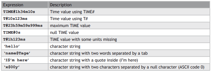
Time constant expressions represent durations that must be less than 24 hours. Expressions must be prefixed by either TIME# or T#. They are expressed as a number of hours followed by h, a number of minutes followed by m, a number of seconds followed by s, and a number of milliseconds followed by ms. The order of units (hour, minutes, seconds, milliseconds) must be respected. You cannot insert blank characters in the time expression. There must be at least one valid unit letter in the expression.
STRING: CHARACTER STRING
String expressions must be written between single quote marks. The length of the string cannot exceed 255 characters. You can use the following sequences to represent a special or not printable character within a string:
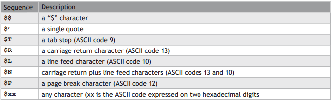
EXAMPLES OF VALID CONSTANT EXPRESSIONS:
EXAMPLES OF TYPICAL ERRORS IN CONSTANT EXPRESSIONS:

Conditional Compiling
The compiler supports conditional compiling directives in ST, LD, and FBD languages. Conditional compiling directives condition the inclusion of a part of the program in the generated code. Conditional compiling is an easy way to manage several various configurations and options in a unique application programming.
Conditional compiling uses definitions as conditions. Below is the main syntax:
#ifdef CONDITION
statementsYES...
#else
statementsNO...
#endif
If CONDITION has been defined using #define syntax, then the statementsYES part is included in the code, else the statementsNO part is included. The #else statement is optional.
In ST and IL text languages, directives must be entered alone on one line line of text. In FBD language, directives must be entered as the text of network breaks. In LD language, directives must be entered on comment lines.
The condition __DEBUG is automatically defined when the application is compiled in DEBUG mode. This allows you to incorporate some additional statements (such as trace outputs) in your code that are not included in RELEASE mode.
Exception handling
The compiler enables you to write your own exception programs for handling particular system events. The following exceptions can be handled:
• Startup (before the first cycle)
• Shutdown (after the last cycle)
• Division by zero
STARTUP
You can write your own exception program to be executed before the first application cycle is executed:
• Create a new main program that will handle the exception. It cannot be a SFC program.
• Add the following global definition:
#OnStartup ProgramName
THE PROGRAM IS EXECUTED BEFORE ALL OTHER PROGRAMS WITHIN THE FISRT CYCLE. THIS IMPLIES THAT THE CYCLE TIMING MAY BE LONGER DURING THE FIRST CYCLE.
YOU CANNOT PUT BREAKPOINTS IN THE STARTUP PROGRAM.
SHUTDOWN
You can write your own exception program to be executed after the last application cycle when the runtime system is cleanly stopped:
• Create a new main program that will handle the exception. It cannot be a SFC program.
• Add the following global definition:
#OnShutdown ProgramName
YOU CANNOT PUT BREAKPOINTS IN THE SHUTDOWN PROGRAM.
DIVISION BY ZERO
You can write your own exception program for handling the “Division by zero” exception. Below is the procedure you must follow for setting an exception handler:
• Create a new sub-program without any parameter that will handle the exception
• In the editor of global defines (auf Seite 74), insert the following line:
#OnDivZero SubProgramName
In the sub-program that handles the exception you can perform any safety or trace operation. You then have the selection between the following possibilities:
• Return without any special call. In that case the standard handling will be performed: a system
error message is generated, the result of the division is replaced by a maximum value and the application continues.
• Call the FatalStop function. The runtime then stops immediately in Fatal Error mode.
• Call the CycleStop function. The runtime finishes the current program and then turns in cycle
setting mode.
Handlers can also be used in DEBUG mode for tracking the bad operation. Just put a breakpoint in your handler. When stopped, the call stack will show you the location of the division in the source code of the program.
ARRAY INDEX OUT OF BOUNDS
You can write your own exception program for handling the “Array index out of bounds” exception. Below is the procedure you must follow for setting an exception handler:
• Create a new sub-program without any parameter that will handle the exception
• In the editor of global defines (auf Seite 74), insert the following line:
#OnBadArrayIndex SubProgramName
This is anyway a fatal error. If the “Check array bounds” compiling option is set, the runtime goes in “fatal error” mode after calling your sub-program.
Variable status bits
The workbench enables you to associate status bits to declared variables. Each variable may have, in addition to its real time value:
• 64 status bits
• a date and time stamp
Status bits and time stamps are generally set by input drivers taking care of hardware inputs, but may also be transported together with the value of the variable on some network protocols. In addition, the IEC
61131-3 programs may access to the status bits of variables.
STATUS BIT MANAGEMENT MAY BE NOT AVAILABLE ON SOME TARGETS. PLEASE REFER TO OEM INSTRUCTIONS FOR FURTHER DETAILS ABOUT AVAILABLE FEATURES
STATUS BIT MANAGEMENT IS CPU AND MEMORY CONSUMING AND MAY REDUCE THE PERFORMANCES OF YOUR APPLICATIONS.
ENABLING STATUS BITS
In order to enable the management of status bits and time/date stamps by the runtime, you must check the following option in the list of compiler options from the Project Settings wizard:
• Allocate status flags for variables with embedded properties
Only variables having some properties defined (either a profile attached or embedded symbol) will get status bits. Status bits are available only for global scope variables (global, retain, IOs...) with a single data type (cannot be array or structure).
READING AND WRITING STATUS FROM PROGRAMS
The following functions are available for managing status information in the programs:
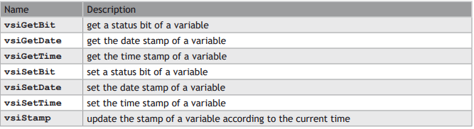
SYNTAX
bBit := vsiGetBit ( variable, bitID );
iDate := vsiGetDate ( variable );
iTime := vsiGetTime ( variable );
bOK := vsiSetBit ( variable, bitID, bBit );
bOK := vsiSetDate ( variable, iDate );
bOK := vsiSetTime ( variable, iTime );
bOK := vsiStamp ( variable );
The functions use the following arguments:


See the description of real time clock functions (auf Seite 2-47) for further information about time and date stamps.
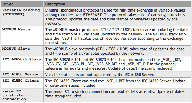
DRIVERS SUPPORTING STATUS BITS
Below are runtime drivers taking care of status bits and date/time stamping:
SEE ALSO
Variable Status Bit List
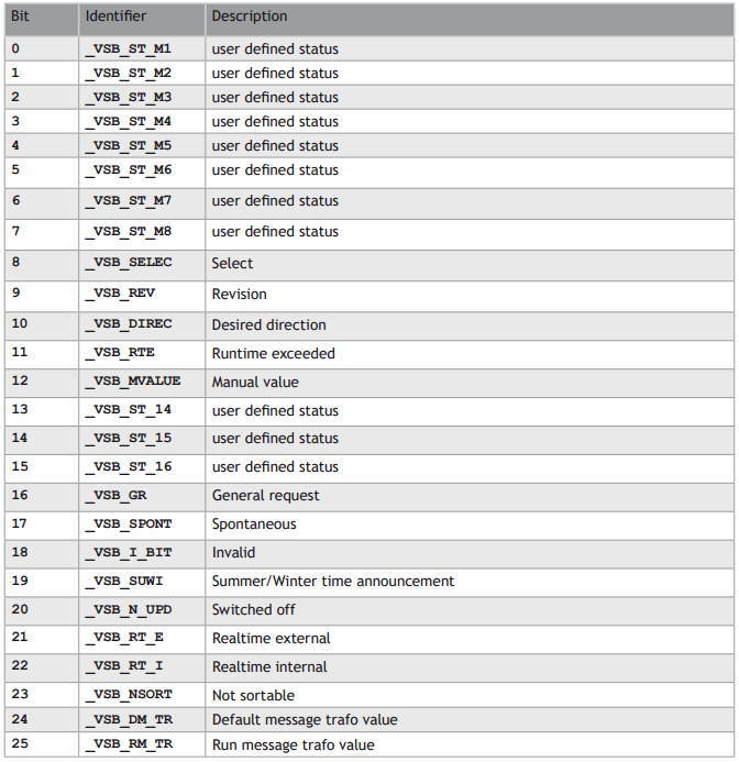
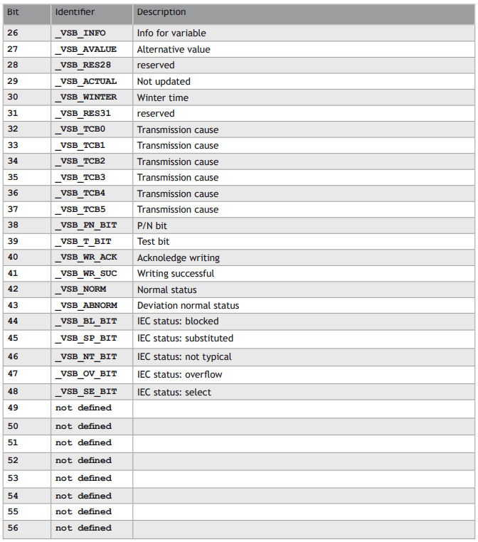
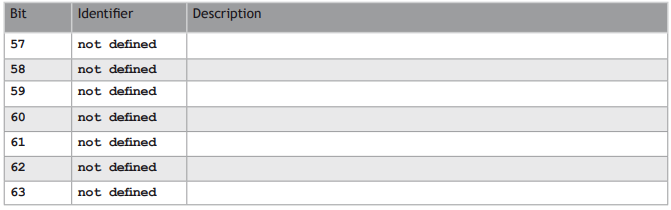
LIST OF VARIABLE STATUS BITS
Below is the list of available status bits. Identifiers (_VSB_...) are predefined in the compiler and can be directly used in the programs:
Basic Operations
LANGUAGE FEATURES - BASIC DATA MANIPULATION
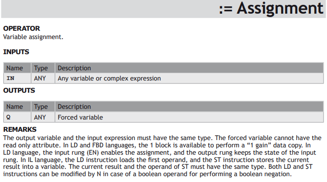
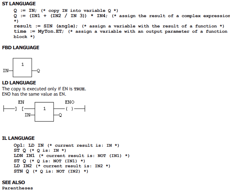
Variable assignment
Bit access
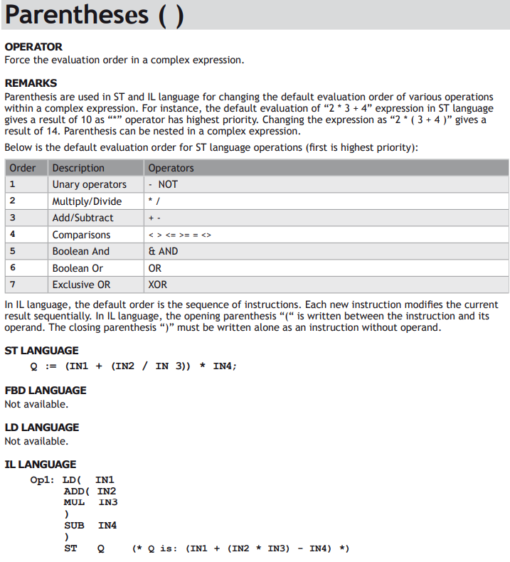
Parentheses
Calling a function
Calling a function block
Calling a sub-program
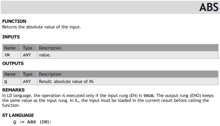
BASIC DATA MANIPULATION FUNCTIONS

LANGUAGE FEATURES - CONTROLLING PROGRAM EXECUTION
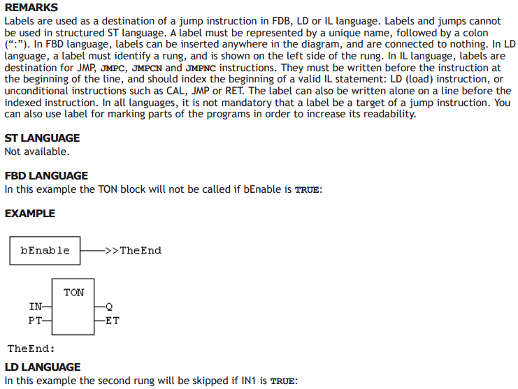
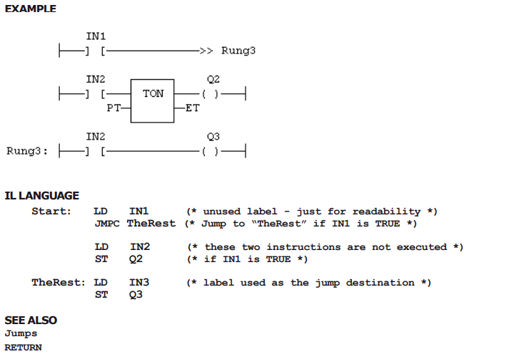
Labels
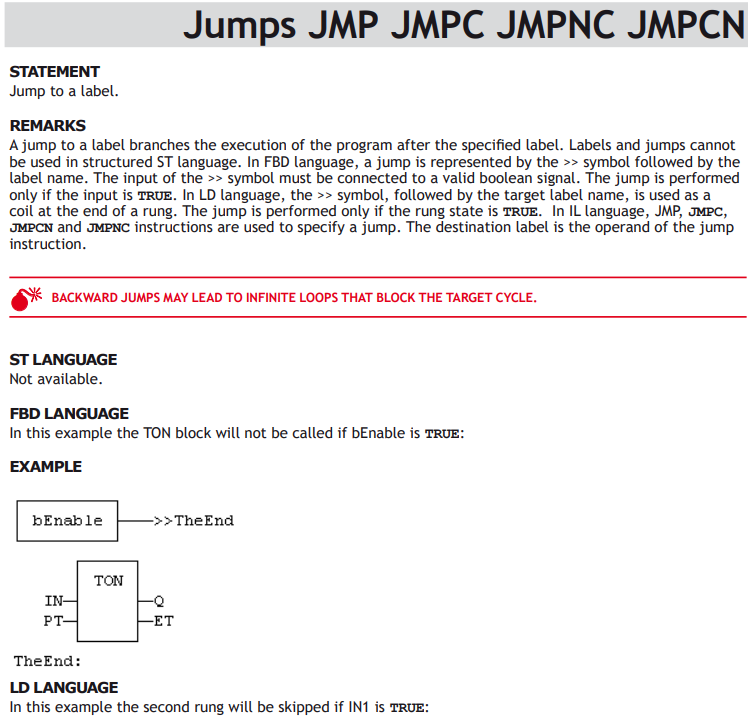
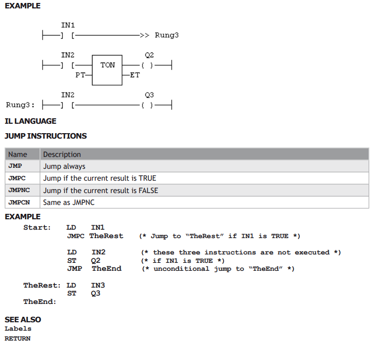
Jumps
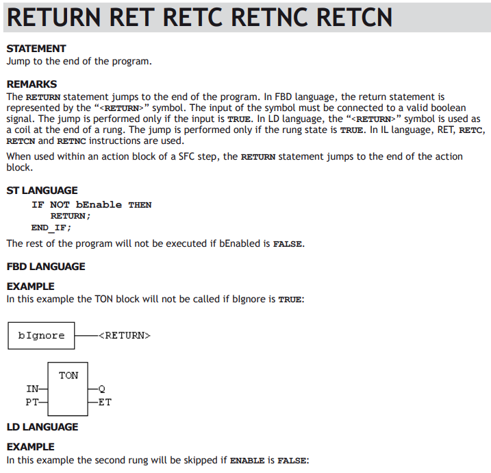
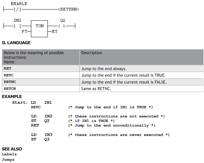
RETURN
STRUCTURED STATEMENTS - CONTROLLING PROGRAM EXECUTION
Access to bits of an integer
You can directly specify a bit within n integer variable in expressions and diagrams, using the following notation:
Variable.BitNo
Where:

The variable can have one of the following data types:
SINT, USINT, BYTE (8 bits from .0 to .7)
INT, UINT, WORD (16 bits from .0 to .15)
DINT, UDINT, DWORD (32 bits from .0 to 31)
LINT (from 0 to 63)
BitNo = 0 always represents the less significant bit.
Calling a function
A function calculates a result according to the current value of its inputs. Unlike a function block, a function has no internal data and is not linked to declared instances. A function has only one output: the result of the function. A function can be:
• Astandard function (SHL, SIN...).
• A function written in “C” language and embedded on the target.
ST LANGUAGE
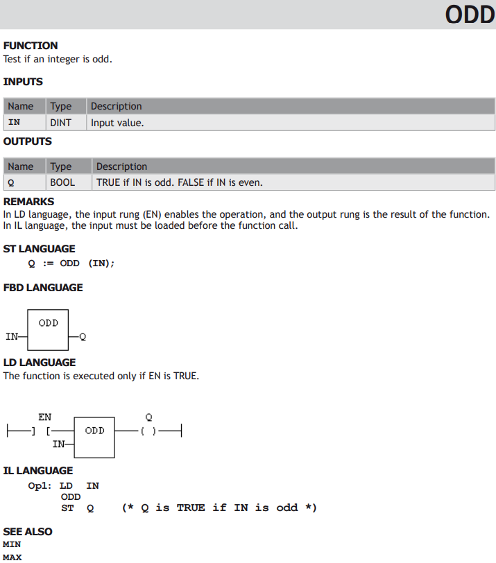
To call a function block in ST, you have to enter its name, followed by the input parameters written between parenthesis and separated by comas. The function call may be inserted into any complex expression. a function call can be used as an input parameter of another function. The following example demonstrates a call to ODD and SEL functions:
EXAMPLE
(* The following statement converts any odd integer value into the nearest even integer: *)
iEvenVal := SEL ( ODD( iValue ), iValue, iValue+1 );
FBD AND LD LANGUAGES
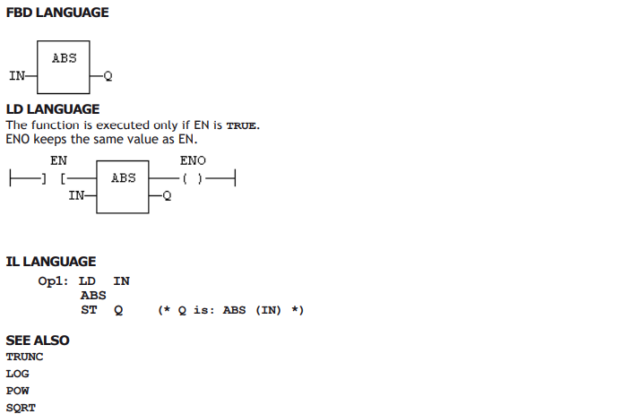
To call a function block in FBD or LD languages, you just need to insert the function in the diagram and to connect its inputs and output.
IL LANGUAGE
To call a function block in IL language, you must load its first input parameter before the call, and then use the function name as an instruction, followed by the other input parameters, separated by comas. The result of the function is then the current result. The following example demonstrates a call to ODD and SEL functions:
EXAMPLE
(* The following statement converts any odd integer into 0: *)
Op1: LD iValue
ODD
SEL iValue, 0
ST iResult
Calling a function block
CAL CALC CALNC CALCN
A function block groups an algorithm and a set of private data. It has inputs and outputs. A function block can be:
1. A standard function block (RS, TON...).
2. A block written in “C” language and embedded on the target.
3. A User Defined Function Block (UDFB) written in ST, FBD, LD or IL.
To use a function block, you have to declare an instance of the block as a variable, identified by a unique name. Each instance of a function block as its own set of private data and can be called separately. A call to a function block instance processes the block algorithm on the private data of the instance, using the specified input parameters.
ST LANGUAGE
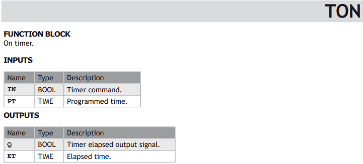
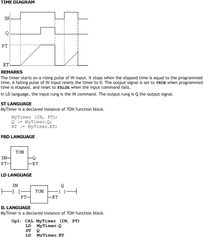
To call a function block in ST, you have to specify the name of the instance, followed by the input parameters written between parenthesis and separated by comas. To have access to an output parameter, use the name of the instance followed by a dot ‘.’ and the name of the wished parameter. The following example demonstrates a call to an instance of TON function block (MyTimer is declared as an instance of TON):
EXAMPLE
MyTimer (bTrig, t#2s);
TimerOutput := MyTimer.Q;
ElapsedTime := MyTimer.ET;
FBD AND LD LANGUAGES
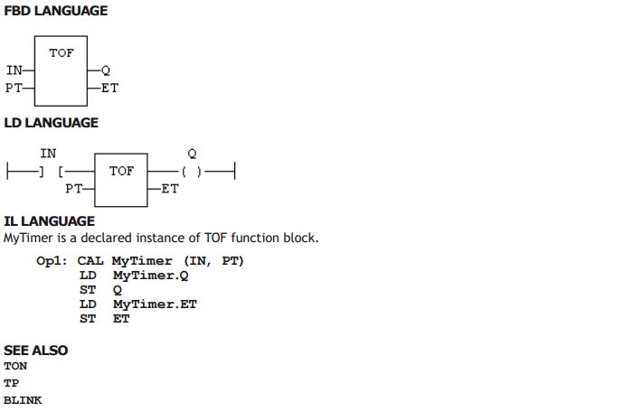
To call a function block in FBD or LD languages, you just need to insert the block in the diagram and to connect its inputs and outputs. The name of the instance must be specified upon the rectangle of the block.
IL LANGUAGE
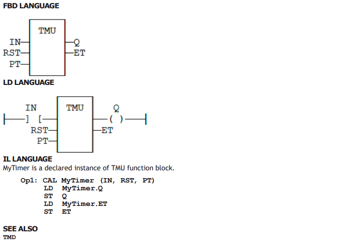
To call a function block in IL language, you must use the CAL instruction, and use a declared instance of the function block. The instance name is the operand of the CAL instruction, followed by the input parameters written between parenthesis and separated by comas. Alternatively the CALC, CALCN or CALNC conditional instructions can be used:

The following example demonstrates a call to an instance of TON function block (MyTimer is declared as an instance of TON):
EXAMPLE
Op1: CAL MyTimer (bTrig, t#2s)
LD MyTimer.Q
ST TimerOutput
LD MyTimer.ET
ST ElapsedTimer
Op2: LD bCond
CALC MyTimer (bTrig, t#2s) (* called only if bCond is TRUE *)
Op3: LD bCond
CALNC MyTimer (bTrig, t#2s) (* called only if bCond is FALSE *)
Calling a sub-program
A sub-program is called by another program. Unlike function blocks, local variables of a sub-program are not instantiated, and thus you do not need to declare instances. A call to a sub-program processes the block algorithm using the specified input parameters. Output parameters can then be accessed.
ST LANGUAGE
To call a sub-program in ST, you have to specify its name, followed by the input parameters written between parenthesis and separated by comas. To have access to an output parameter, use the name of the subprogram followed by a dot ‘.’ and the name of the wished parameter:
MySubProg (i1, i2); (* calls the sub-program *)
Res1 := MySubProg.Q1;
Res2 := MySubProg.Q2;
Alternatively, if a sub-program has one and only one output parameter, it can be called as a function in ST language:
Res := MySubProg (i1, i2);
FBD AND LD LANGUAGES
To call a sub-program in FBD or LD languages, you just need to insert the block in the diagram and to connect its inputs and outputs.
IL LANGUAGE
To call a sub-program in IL language, you must use the CAL instruction with the name of the sub-program, followed by the input parameters written between parenthesis and separated by comas. Alternatively the CALC, CALCN or CALNC conditional instructions can be used:

EXAMPLE
Op1: CAL MySubProg (i1, i2)
LD MySubProg.Q1
ST Res1
LD MySubProg.Q2
ST Res2



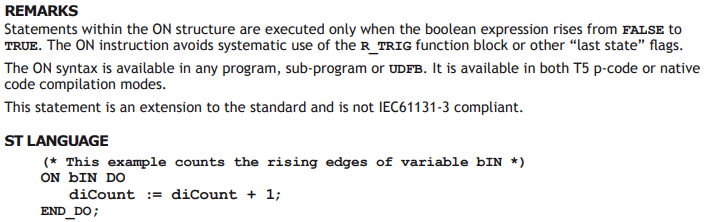
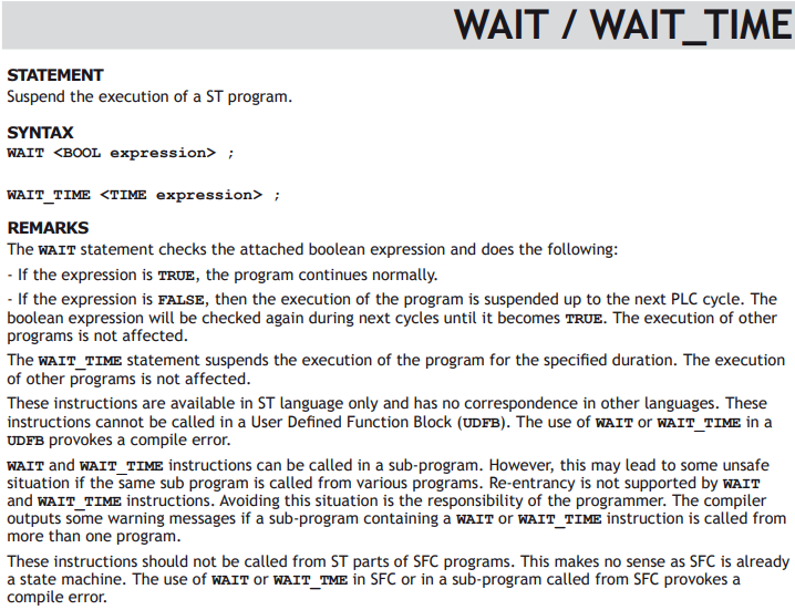
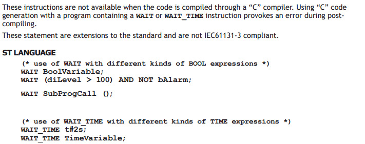
Boolean Operations
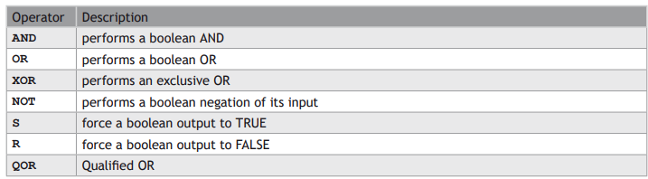
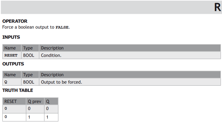
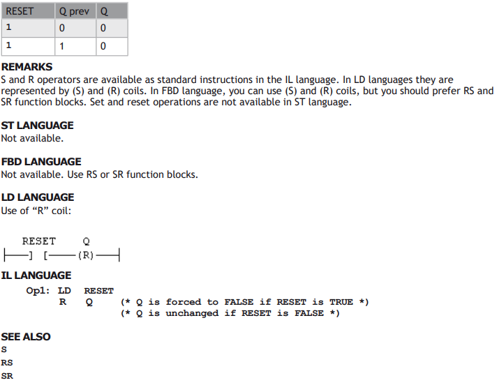
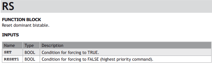
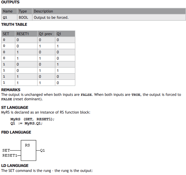
STANDARD OPERATORS FOR MANAGING BOOLEANS:
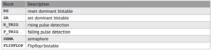
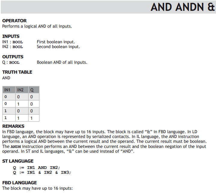
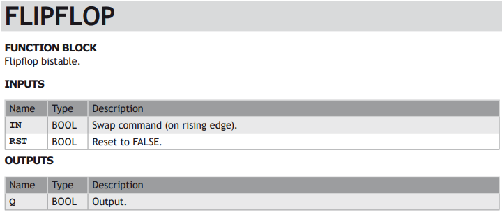
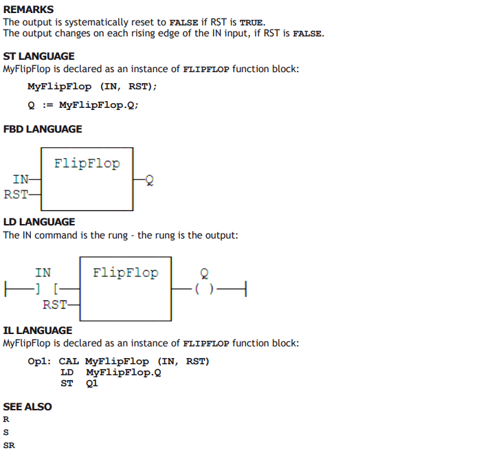
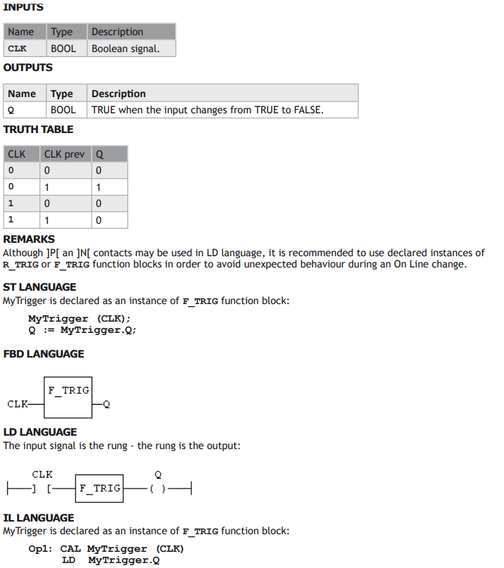
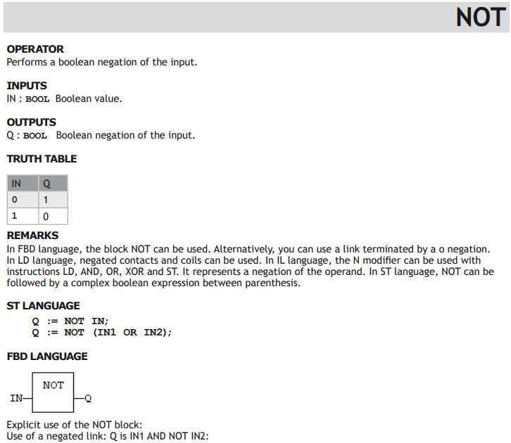
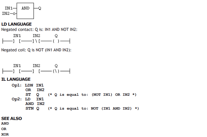
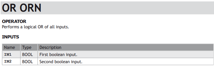
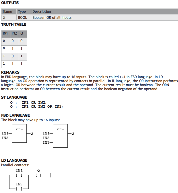
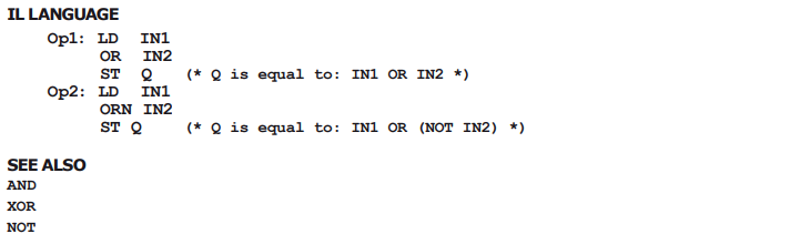
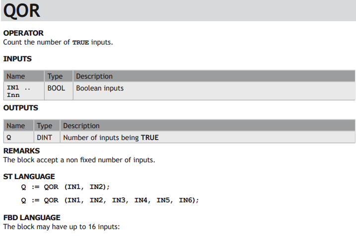
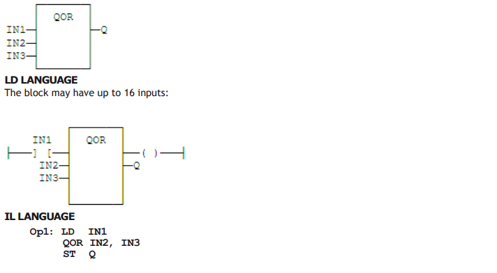
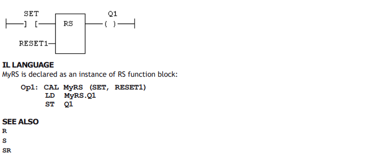
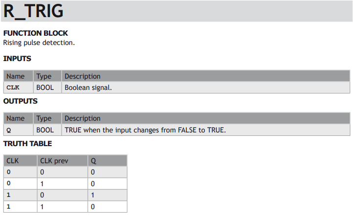
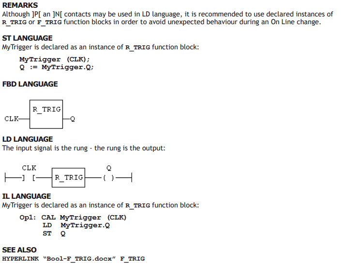
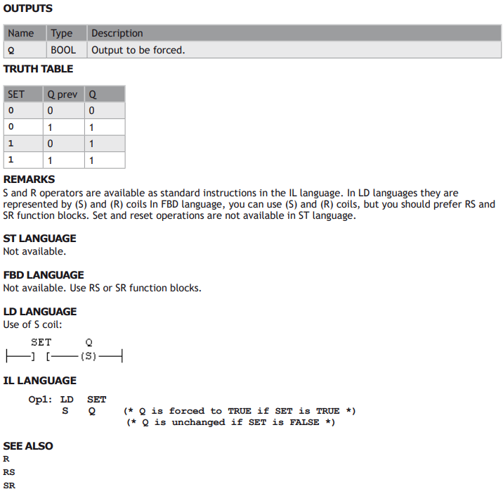
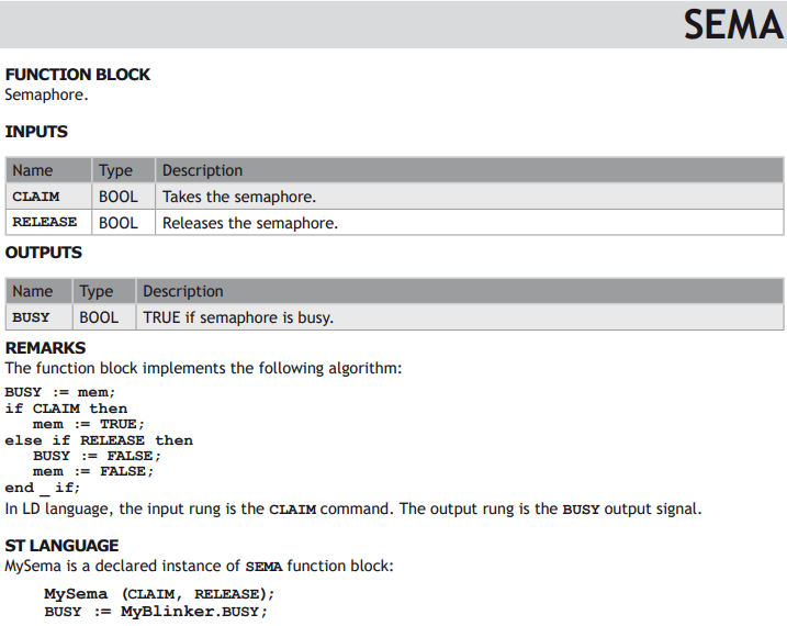
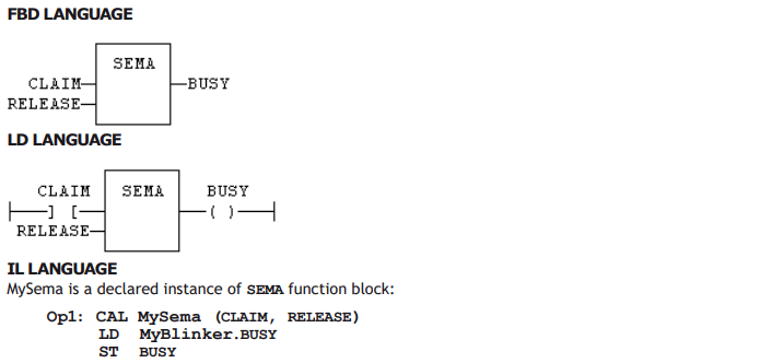
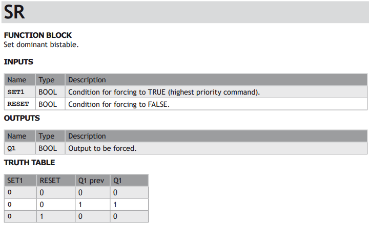
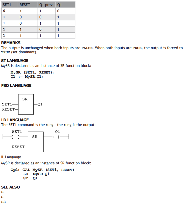
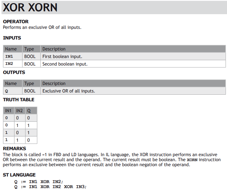
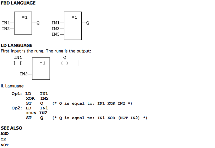
AVAILABLE BLOCKS FOR MANAGING BOOLEAN SIGNALS:



Arithmetic Operations
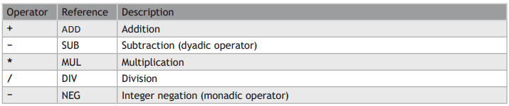
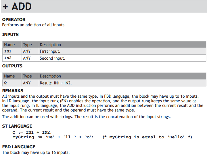
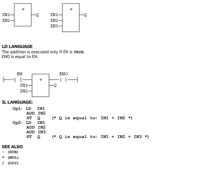
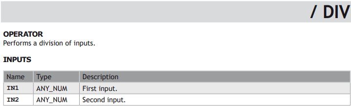
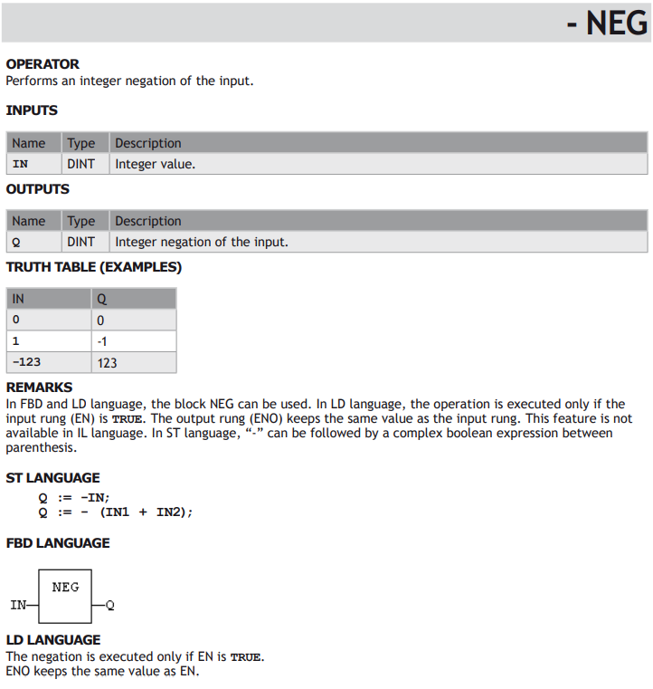
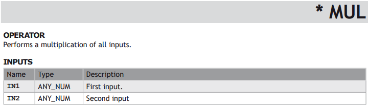
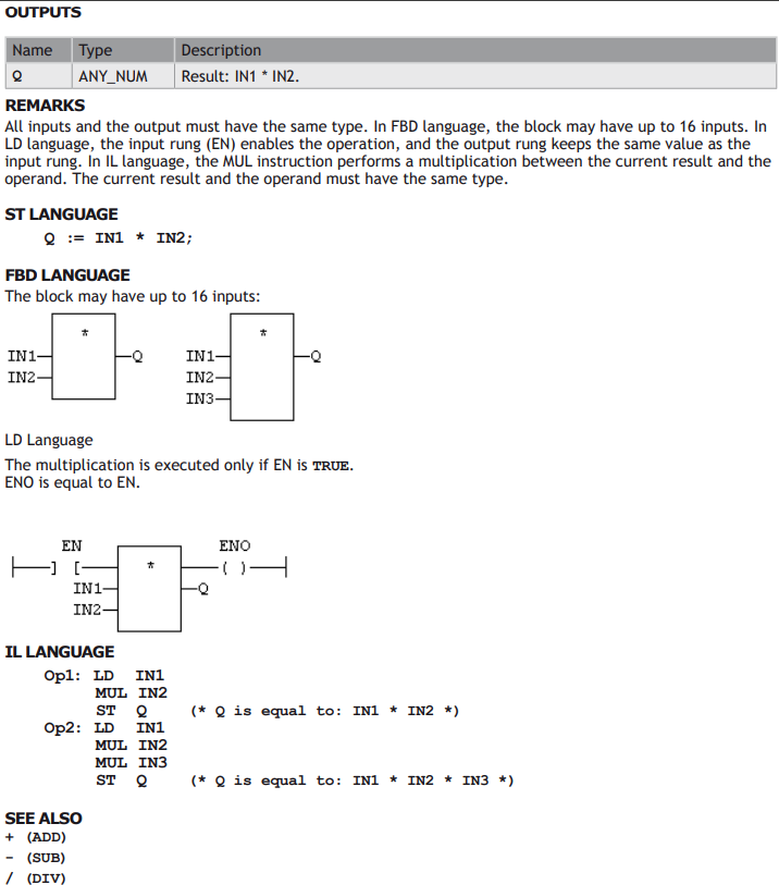
STANDARD OPERATORS
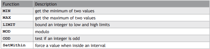
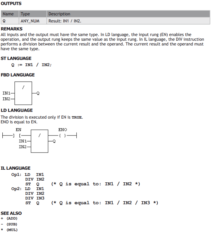
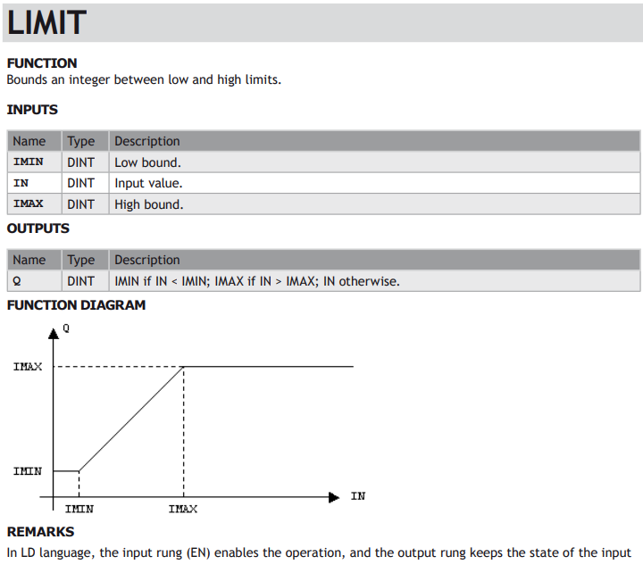
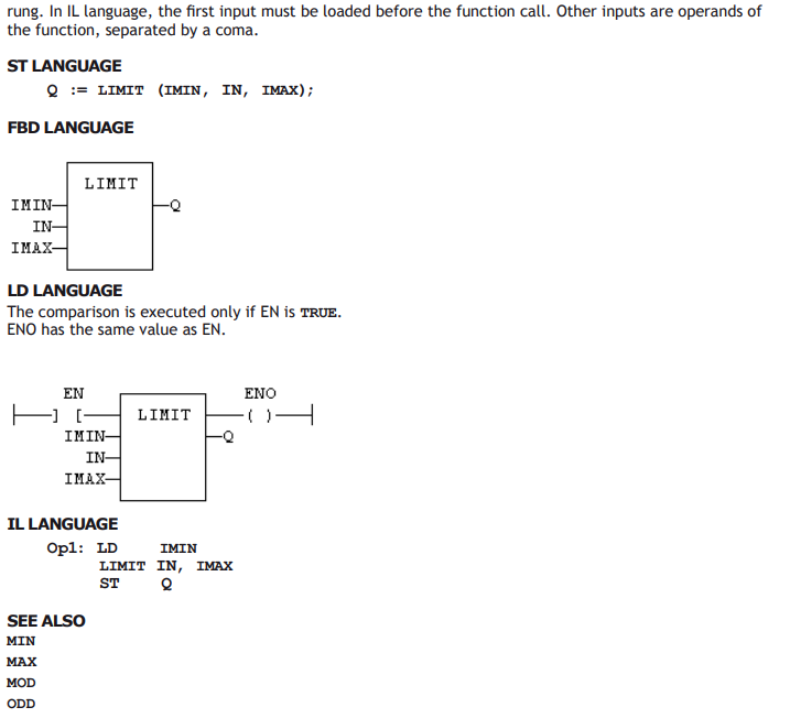
STANDARD FUNCTIONS


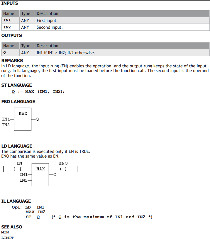

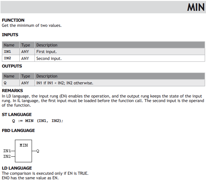
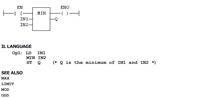
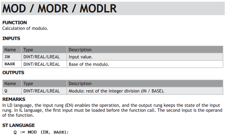

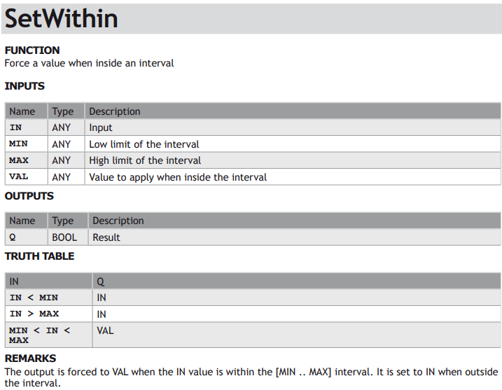

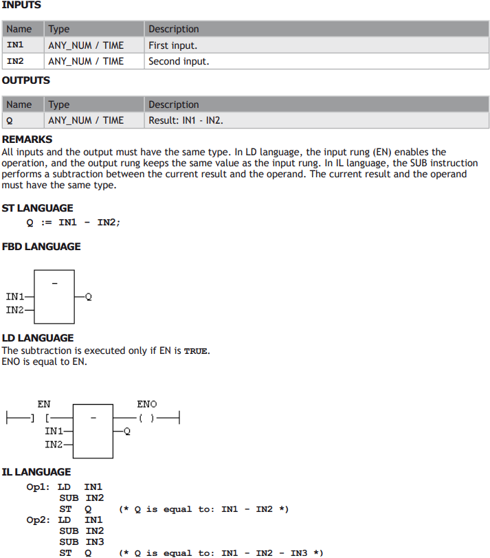

Comparison Operations
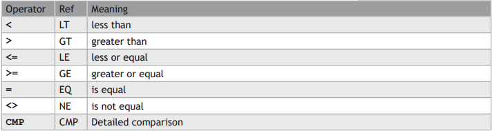
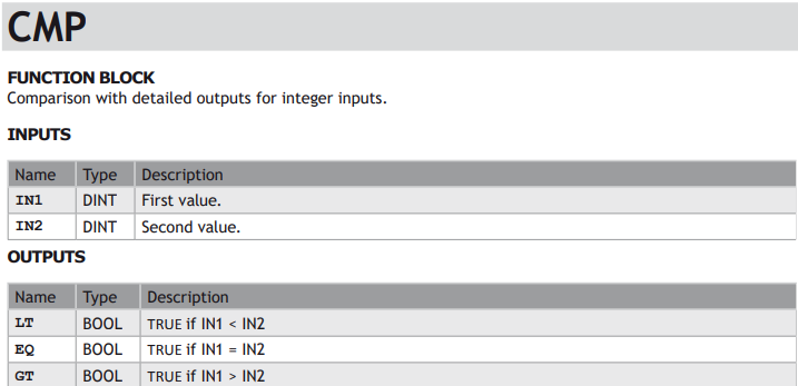
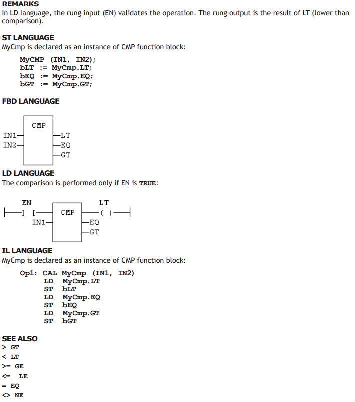
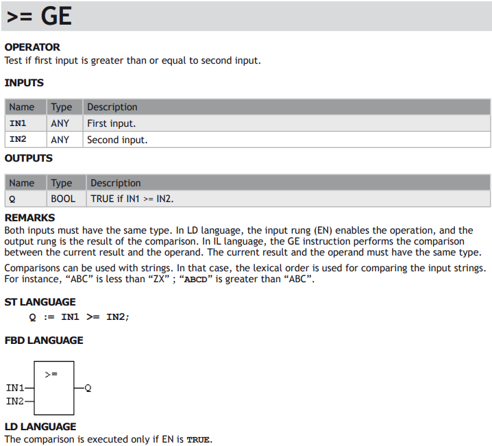
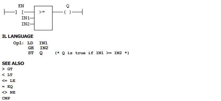
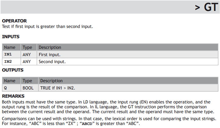
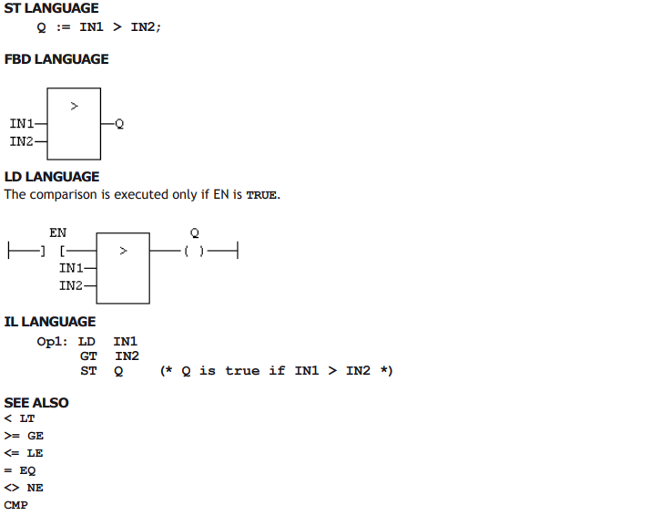
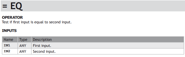
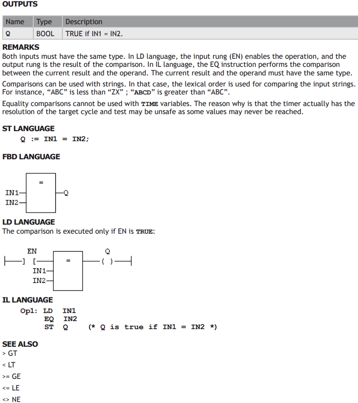
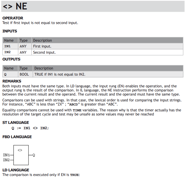
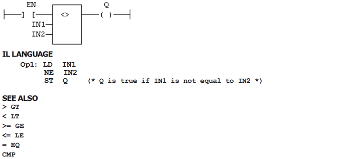
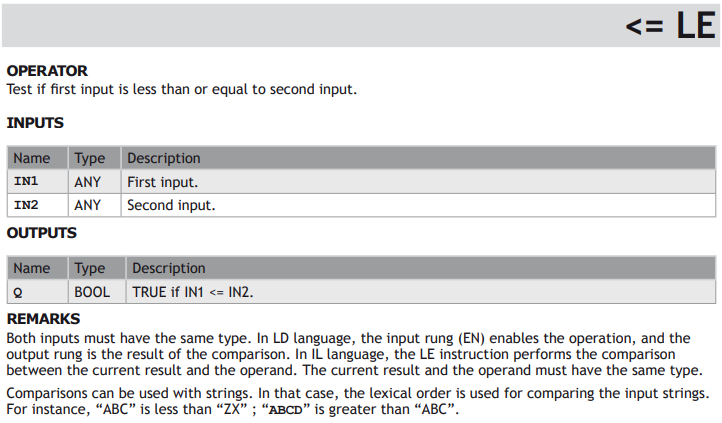
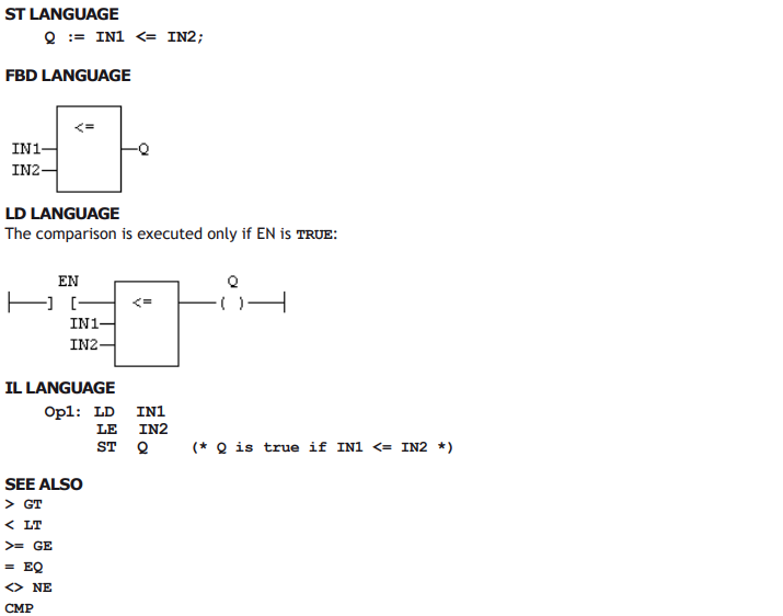
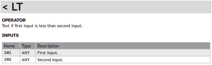
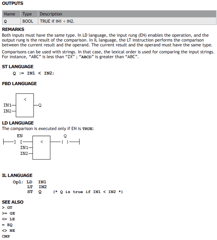
STANDARD OPERATORS AND BLOCKS THAT PERFORM COMPARISONS:

Type Conversion Functions
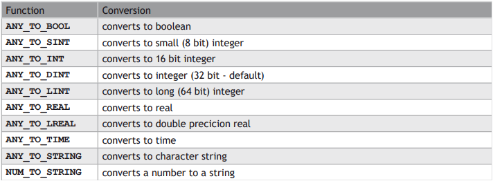
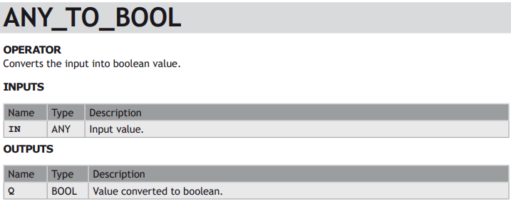
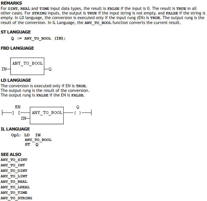
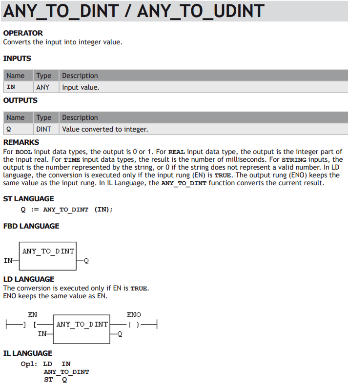
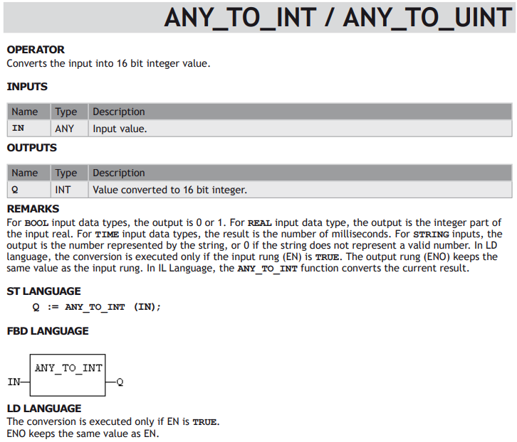
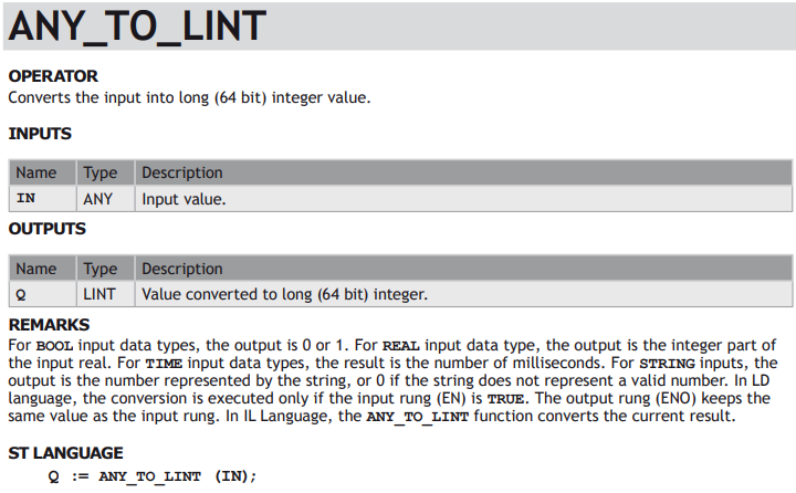
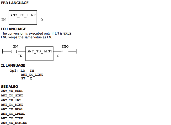
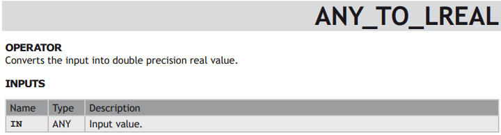
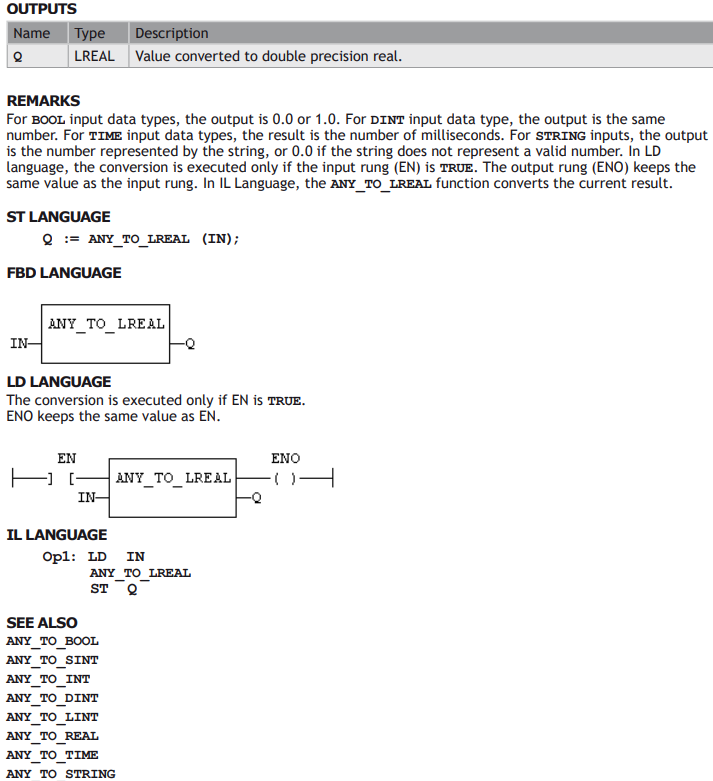
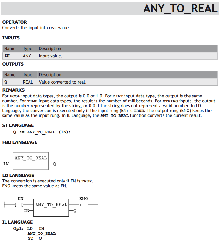
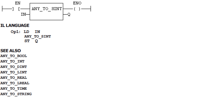
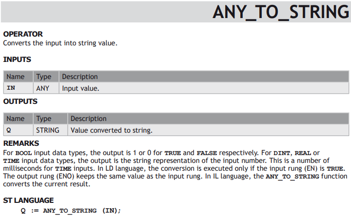
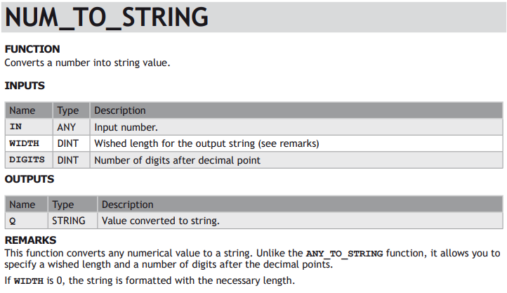
STANDARD FUNCTIONS FOR CONVERTING A DATA ELEMENT INTO ANOTHER DATA TYPE:
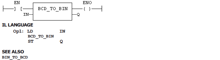
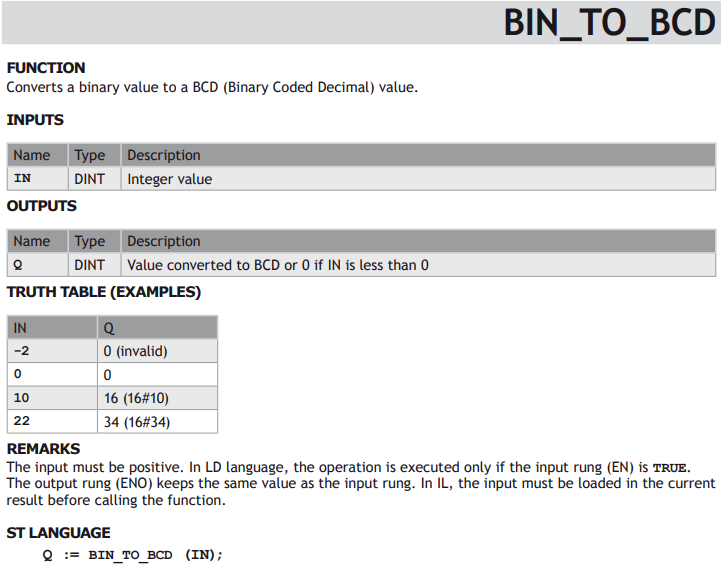
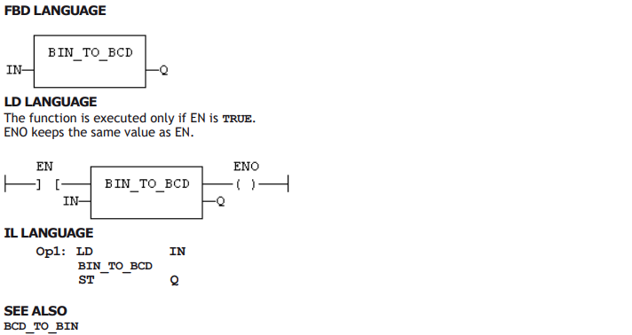
STANDARD FUNCTIONS PERFORMING CONVERSIONS IN BCD FORMAT (*):


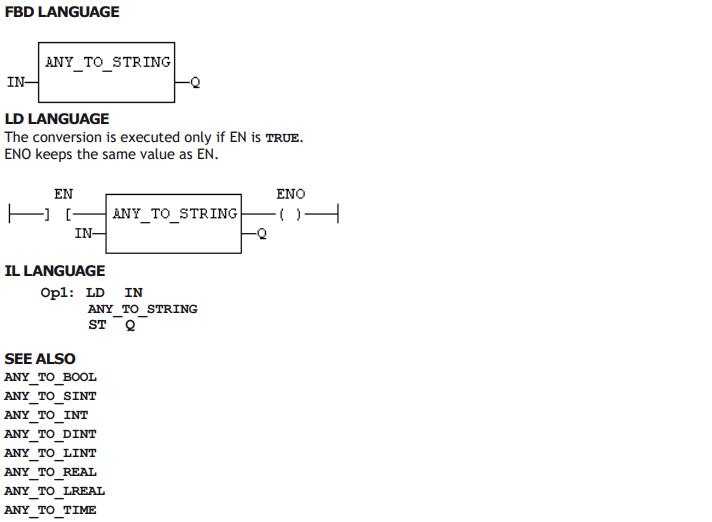
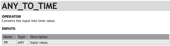
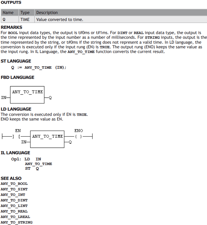
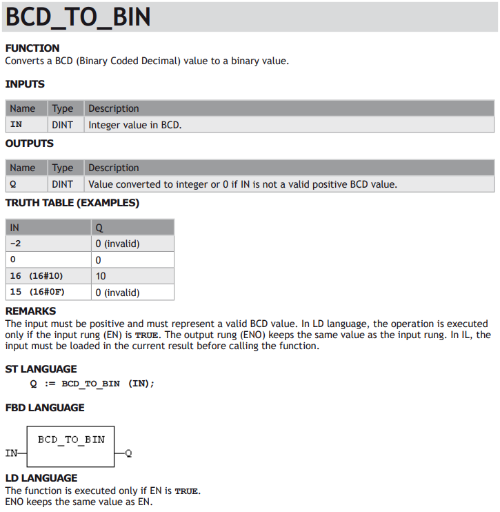
Selectors
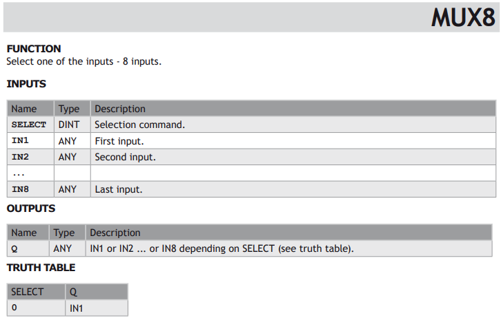
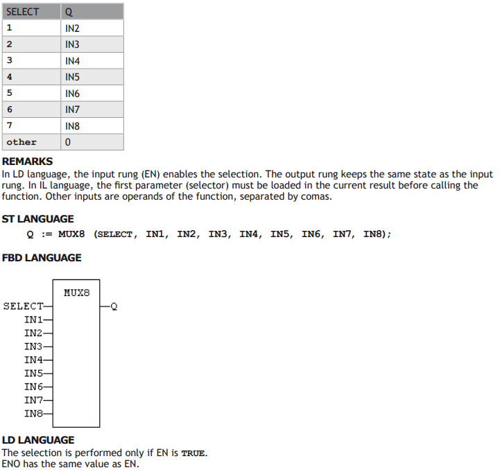
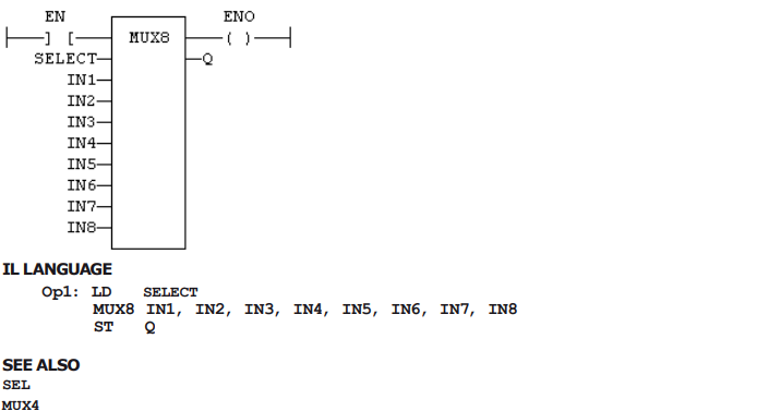
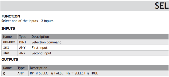
STANDARD FUNCTIONS THAT PERFORM DATA SELECTION:

Registers
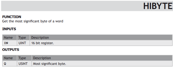
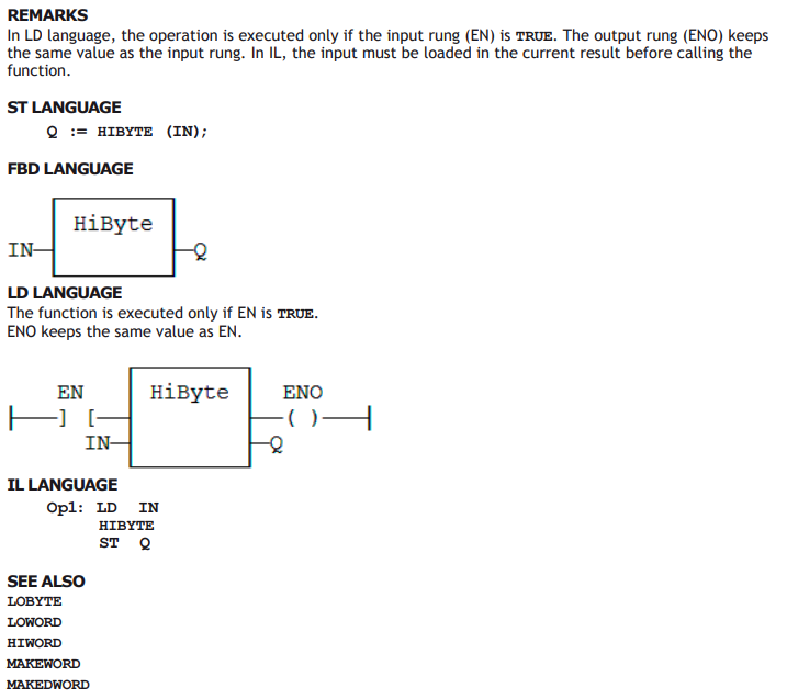
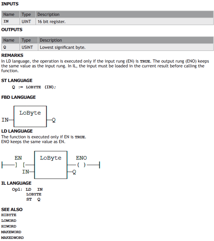
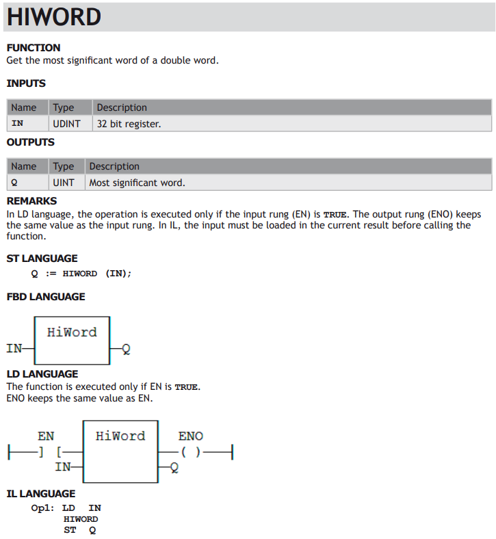
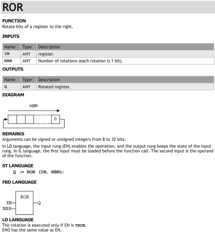
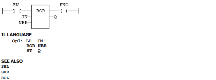
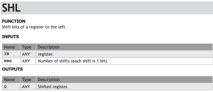
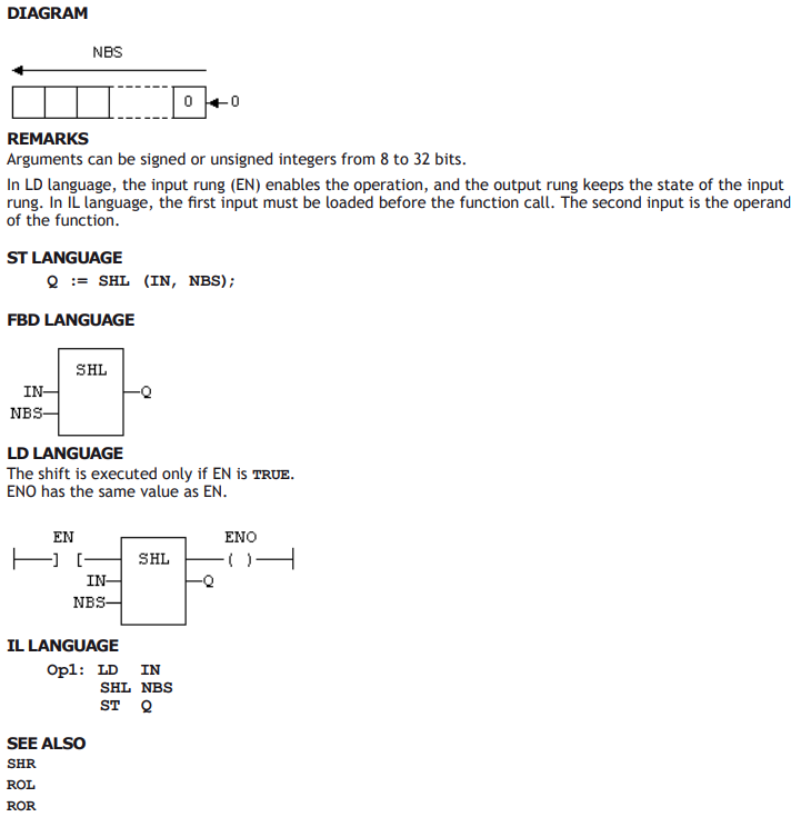
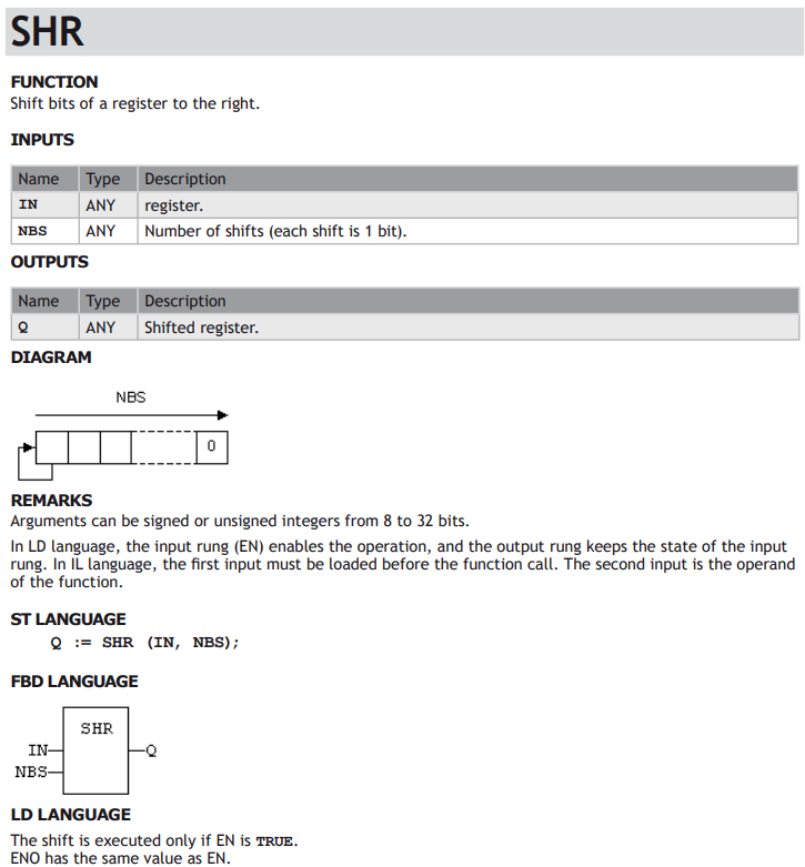
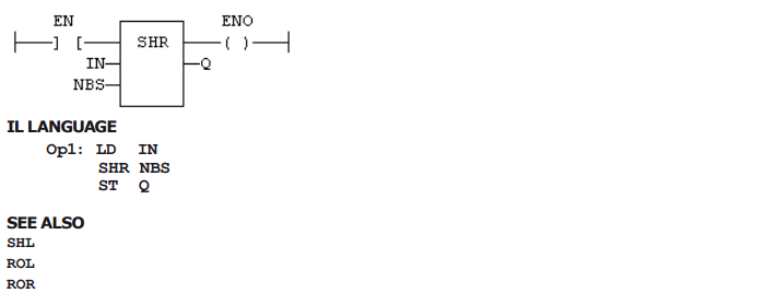
STANDARD FUNCTIONS FOR MANAGING 8 BIT TO 32 BIT REGISTERS:

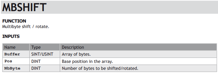
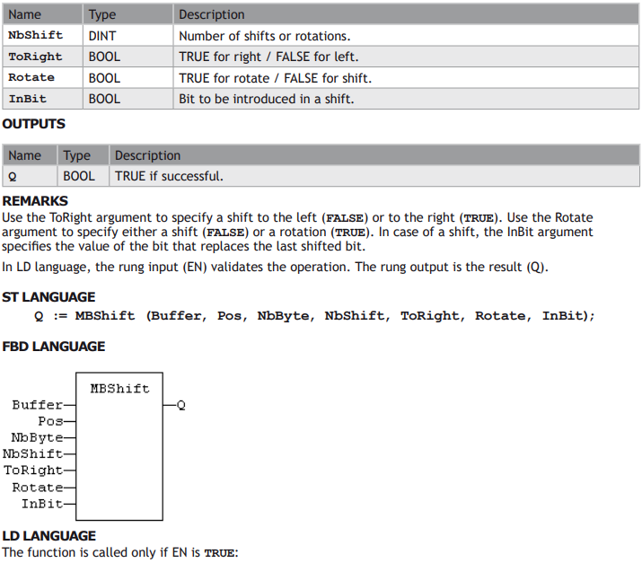
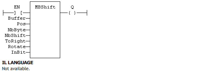
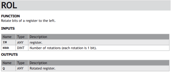
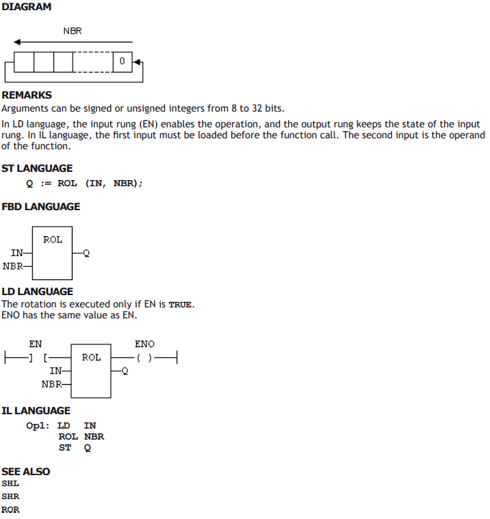
ADVANCED FUNCTIONS FOR REGISTER MANIPULATION:

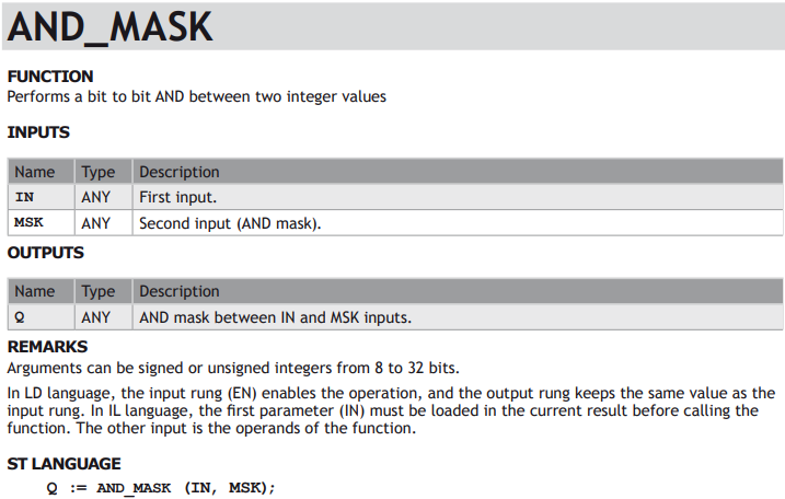
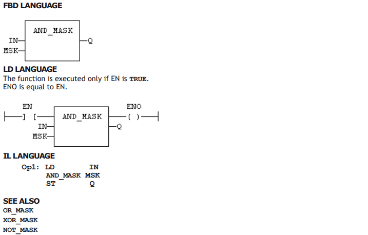
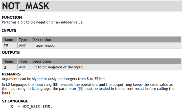
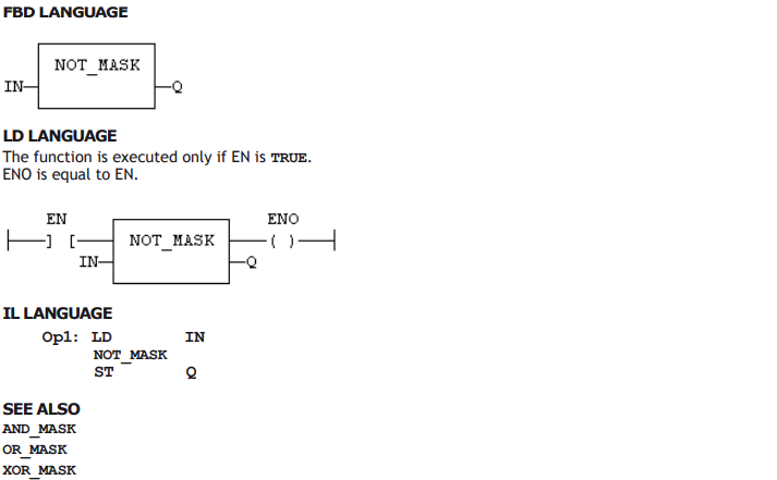
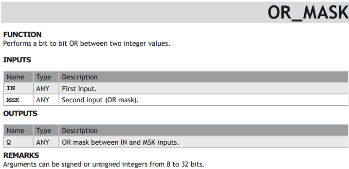
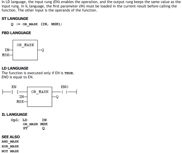
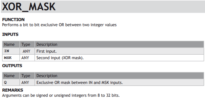
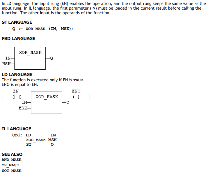
BIT TO BIT OPERATIONS ON A 8 BIT TO 32 BIT INTEGERS:

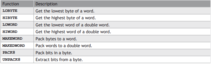
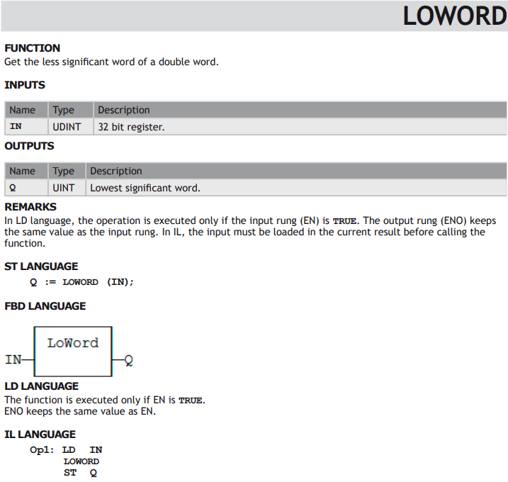
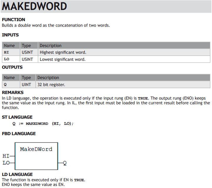
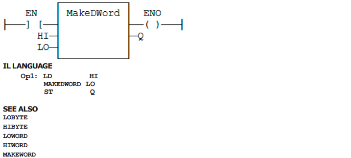
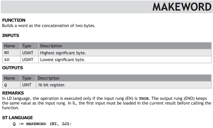
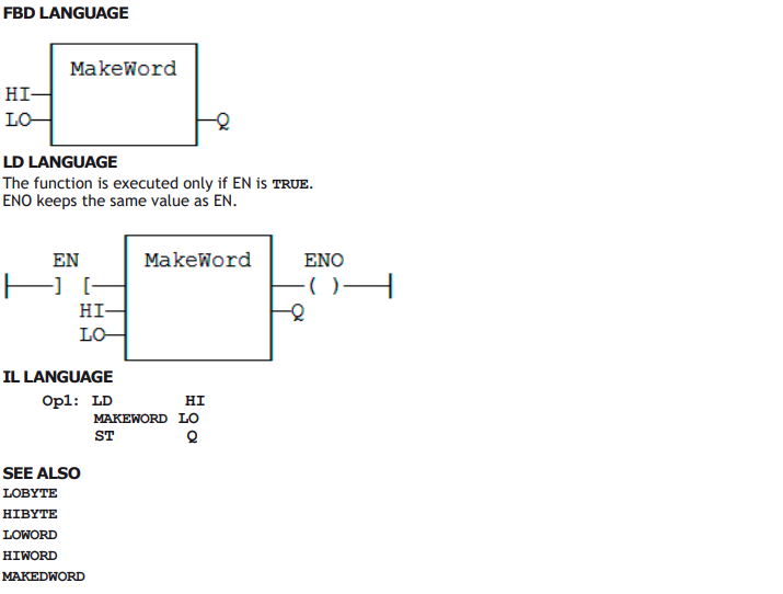
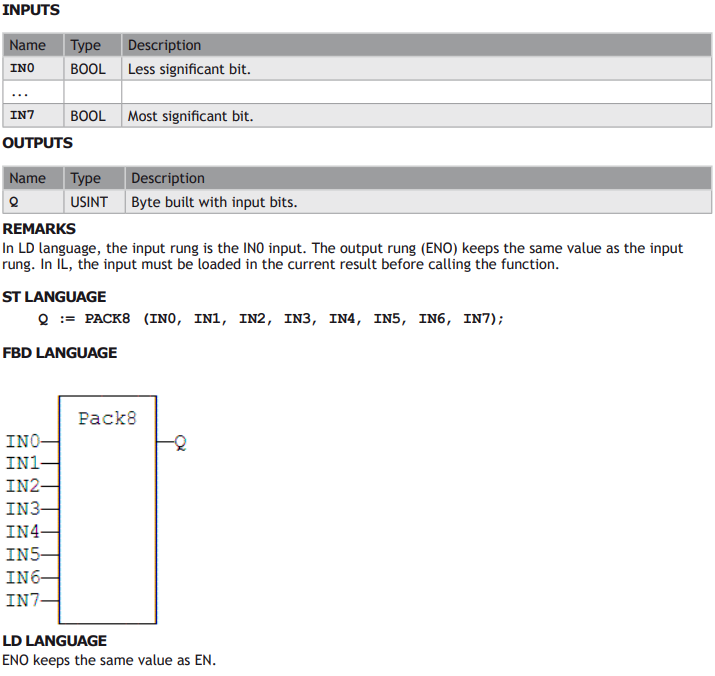
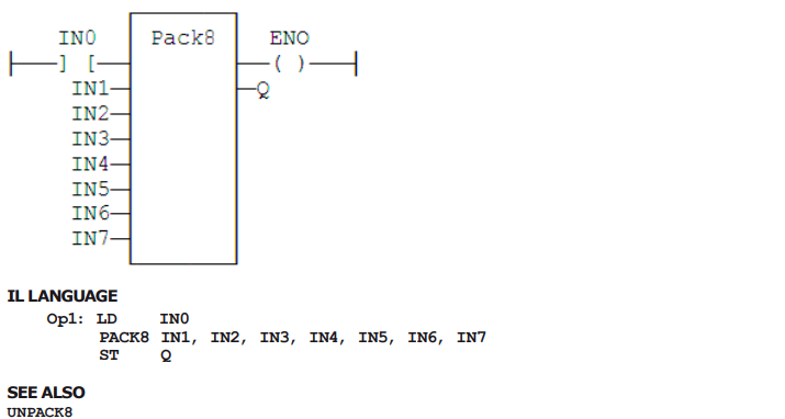
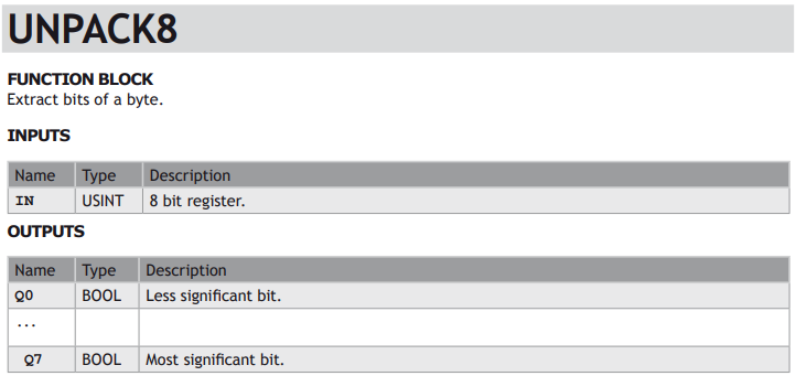
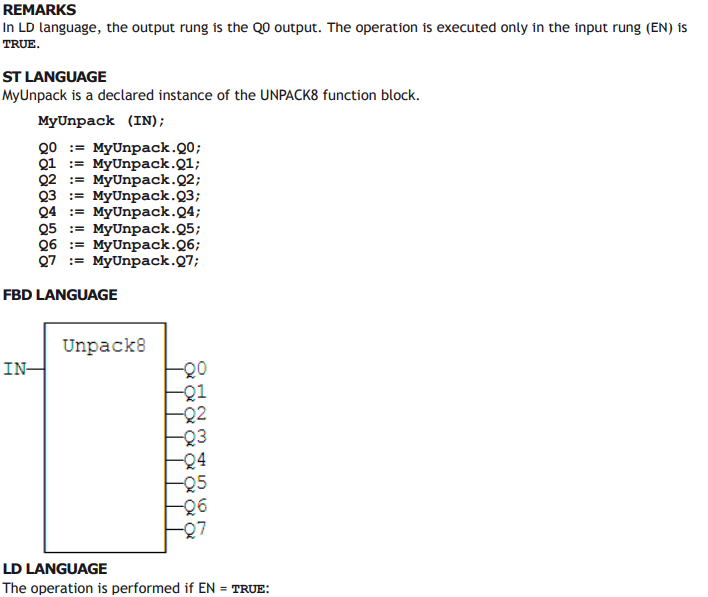
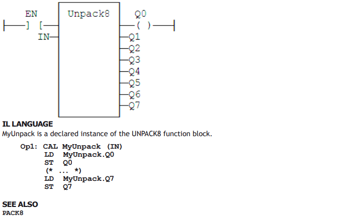
PACK/UNPACK 8, 16 AND 32 BIT REGISTERS
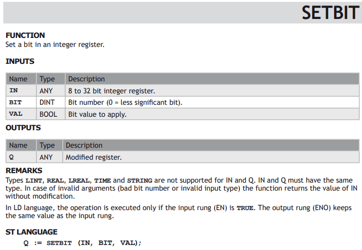
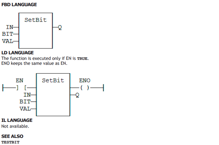
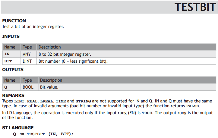
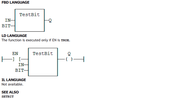
BIT ACCESS IN 8 BIT TO 32 BIT INTEGERS:

The following functions are kept for compatibility, but you should use the functions above:
AND_DINT, AND_UDINT, AND_DWORD, NOT_DINT, NOT_UDINT, NOT_DWORD
OR_DINT, OR_UDINT, OR_DWORD, XOR_DINT, XOR_UDINT, XOR_DWORD
AND_INT, AND_UINT, AND_WORD, NOT_INT, NOT_UINT, NOT_WORD
OR_INT, OR_UINT, OR_WORD, XOR_INT, XOR_UINT, XOR_WORD
AND_SINT, AND_USINT, AND_BYTE, NOT_SINT, NOT_USINT, NOT_BYTE
OR_SINT, OR_USINT, OR_BYTE, XOR_SINT, XOR_USINT, XOR_BYTE
ROLw, RORw, SHLw, SHRw, ROLb, RORrb, SHLb, SHRb
ROL_DINT, ROR_DINT, SHL_DINT, SHR_DINT
ROL_UDINT, ROR_UDINT, SHL_UDINT, SHR_UDINT
ROL_DWORD, ROR_DWORD, SHL_DWORD, SHR_DWORD
ROL_INT, ROR_INT, SHL_INT, SHR_INT
ROL_UINT, ROR_UINT, SHL_UINT, SHR_UINT
ROL_WORD, ROR_WORD, SHL_WORD, SHR_WORD
ROL_SINT, ROR_SINT, SHL_SINT, SHR_SINT
ROL_USINT, ROR_USINT, SHL_USINT, SHR_USINT
ROL_BYTE, ROR_BYTE, SHL_BYTE, SHR_BYTE




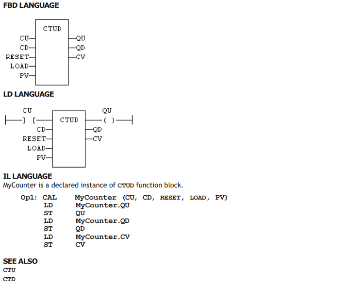
Counters
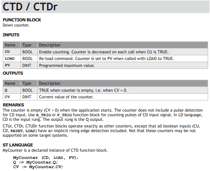
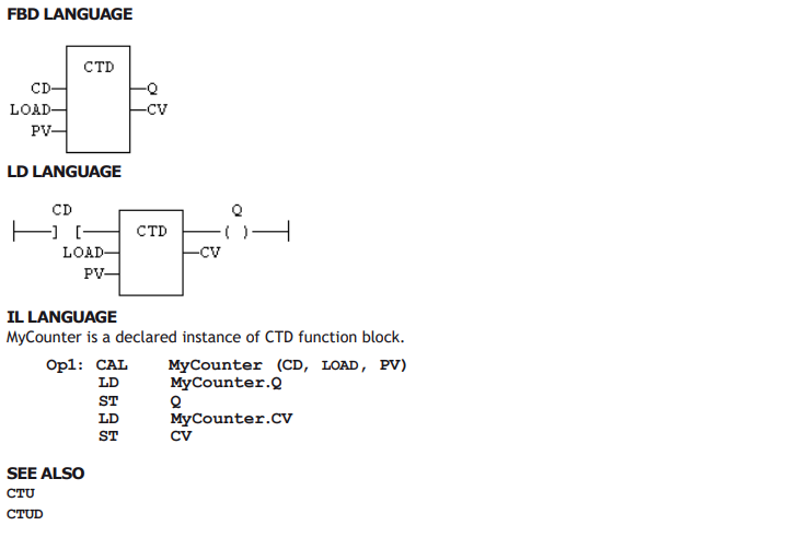
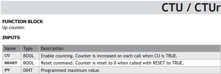
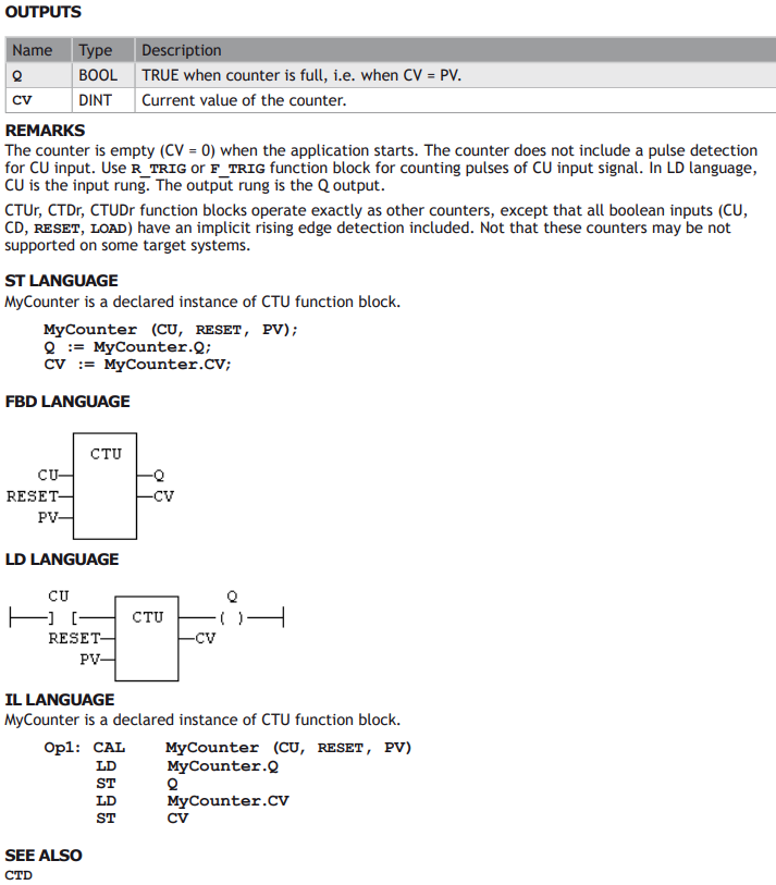
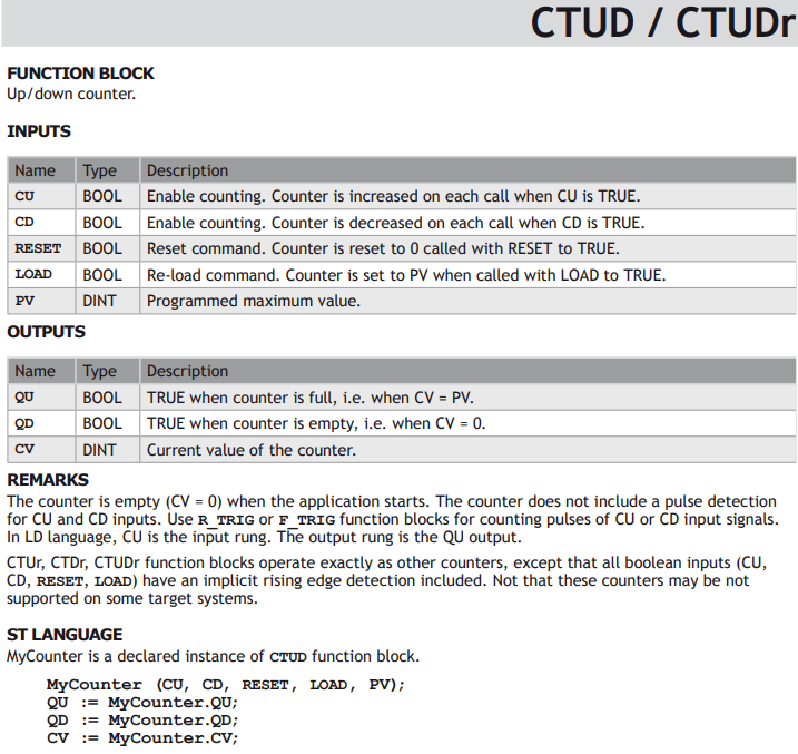
Standard blocks for managing counters:

Timers
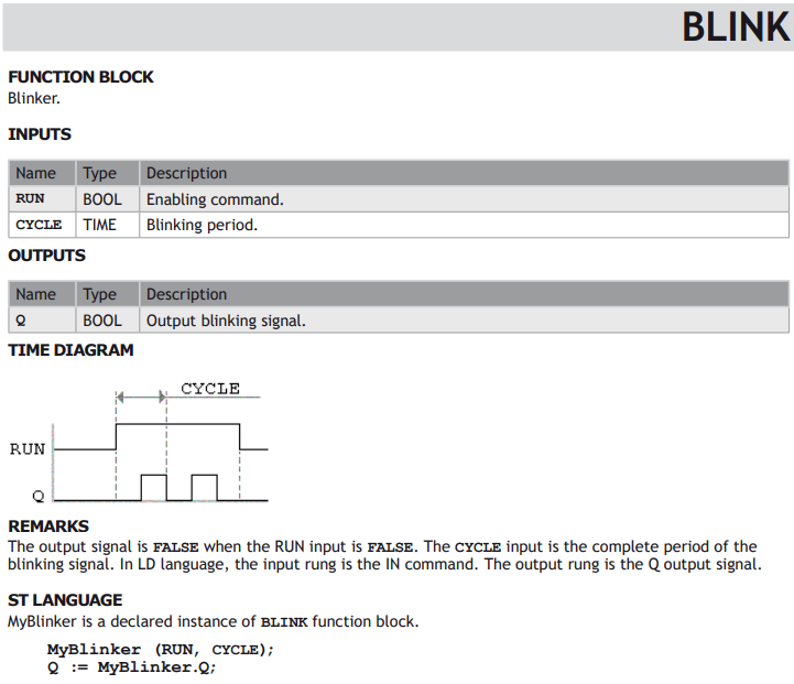
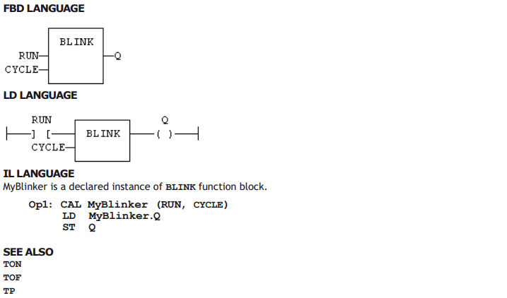
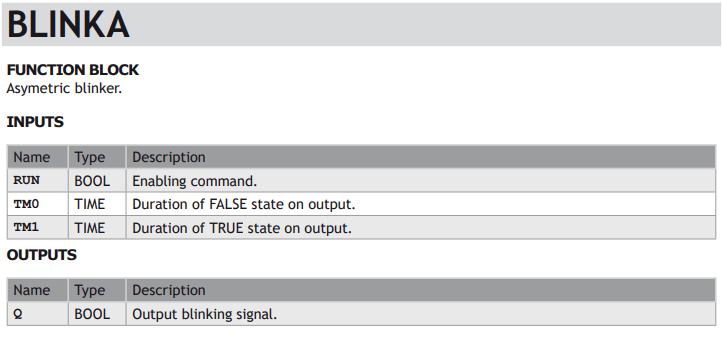
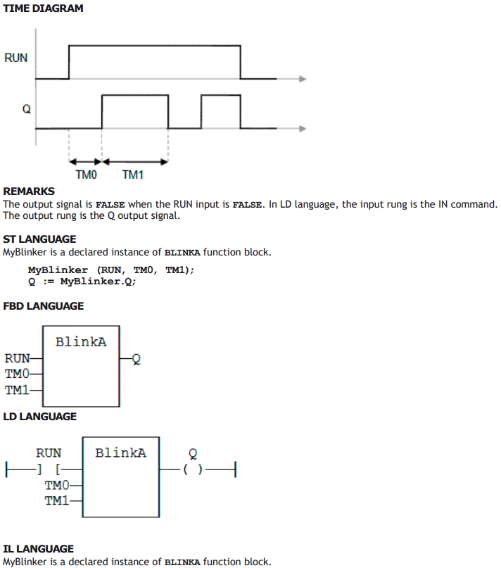
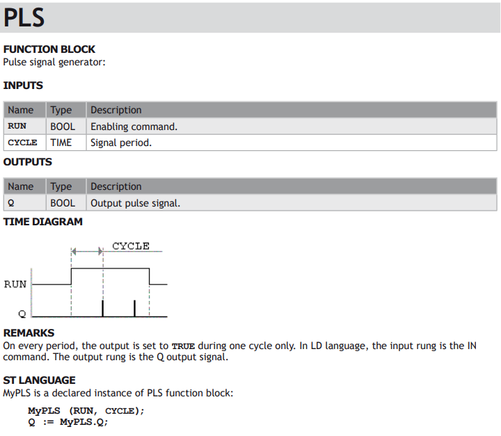
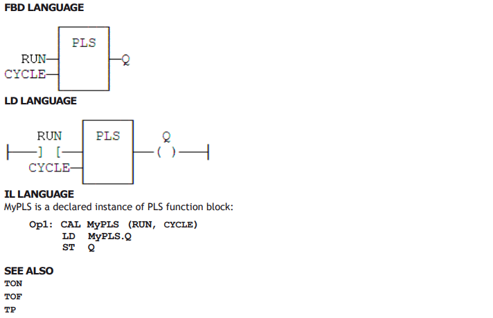
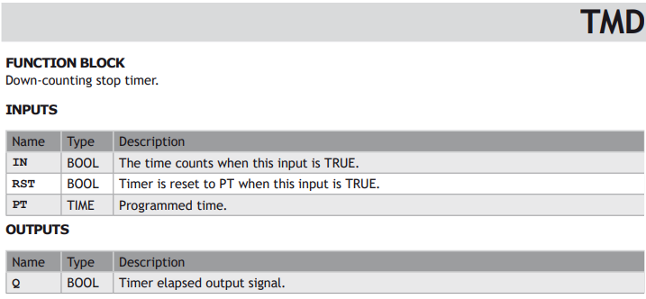
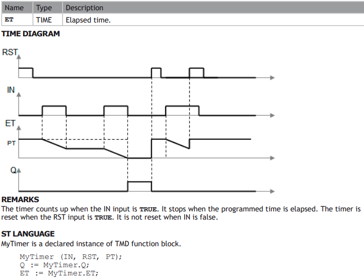
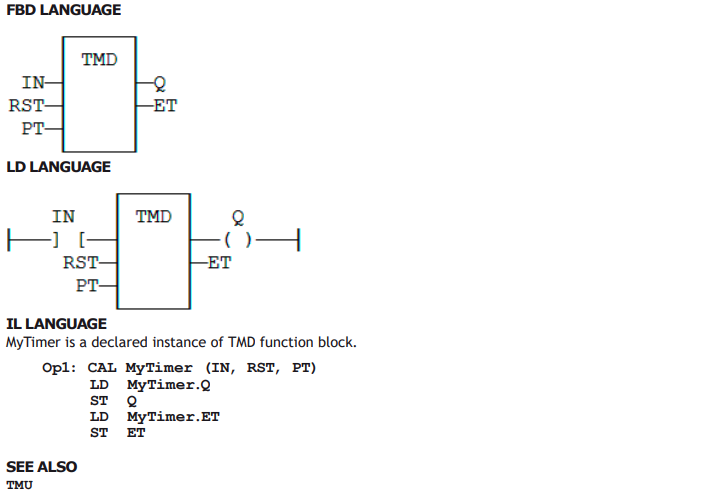
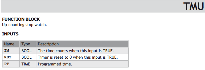
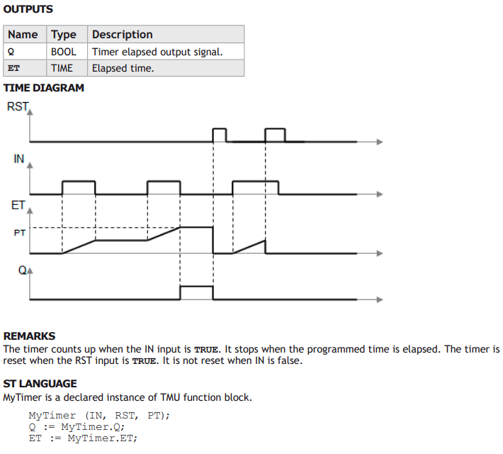
STANDARD FUNCTIONS FOR MANAGING TIMERS:




Mathematical Operations
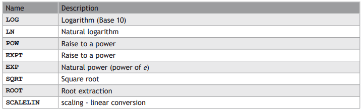
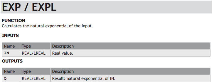
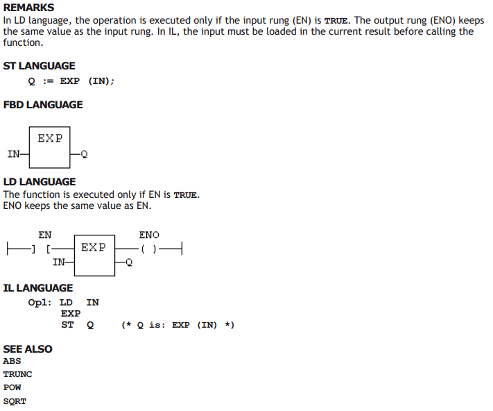
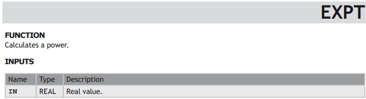
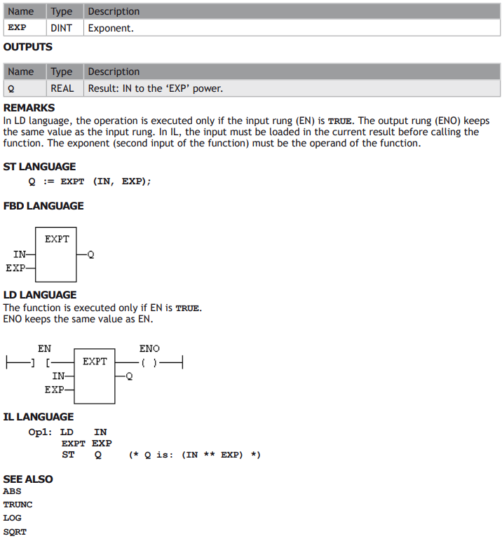
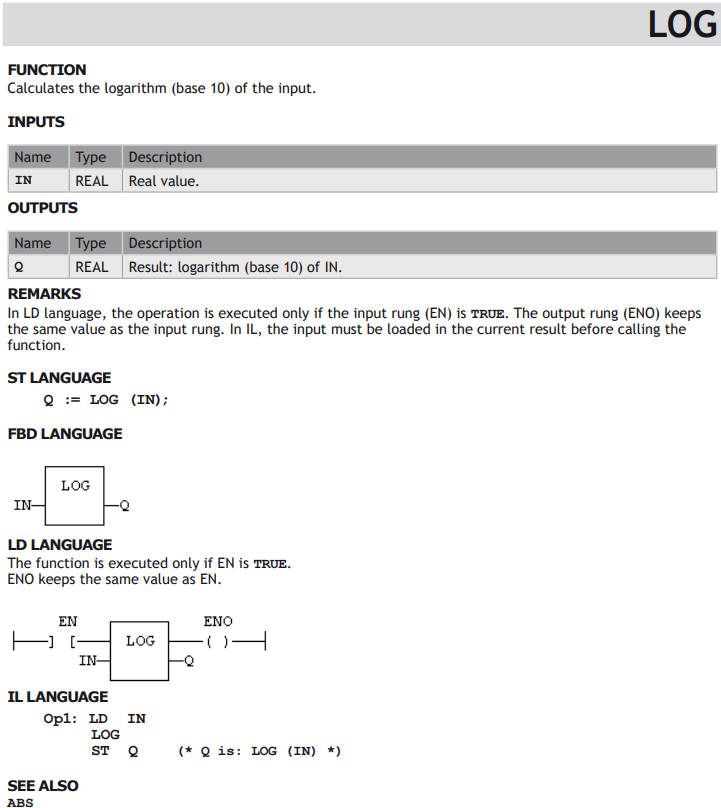
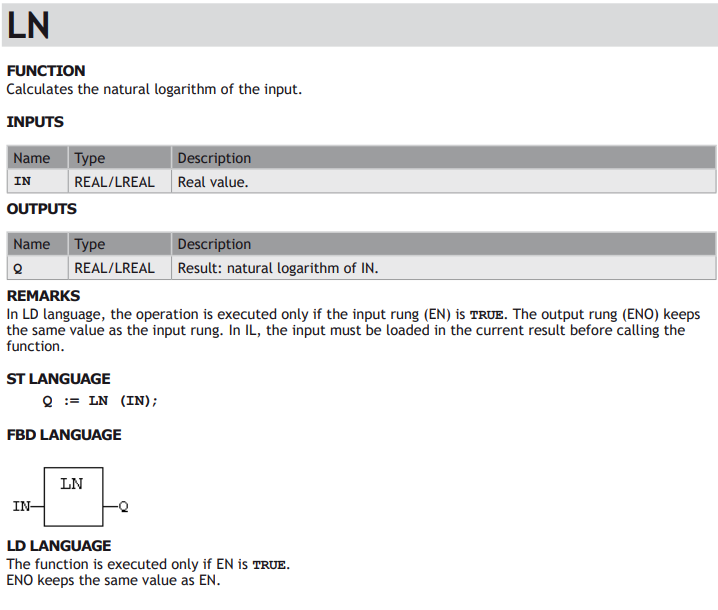
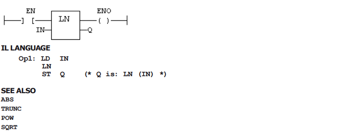
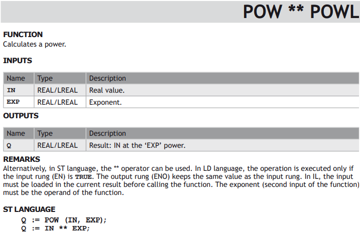
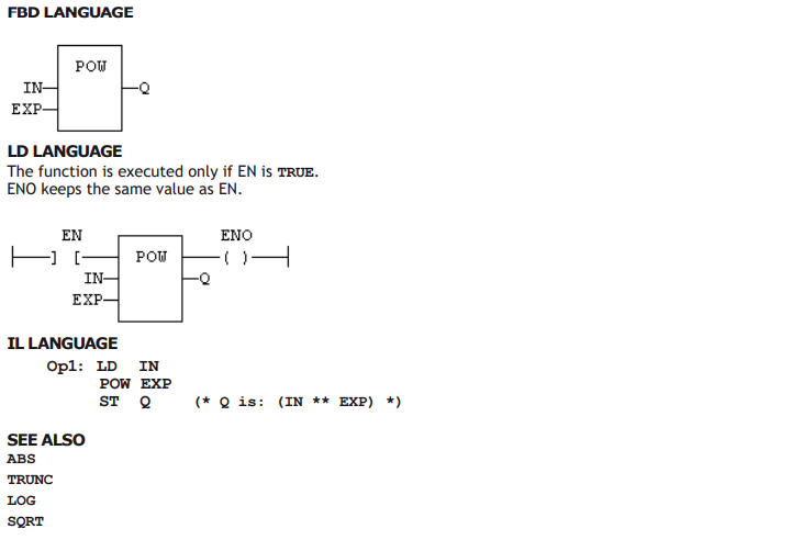
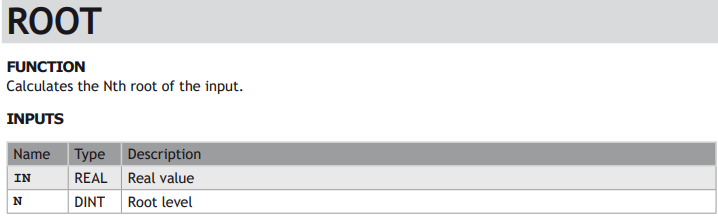
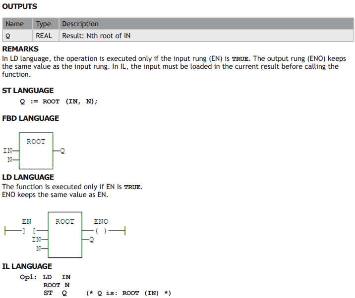
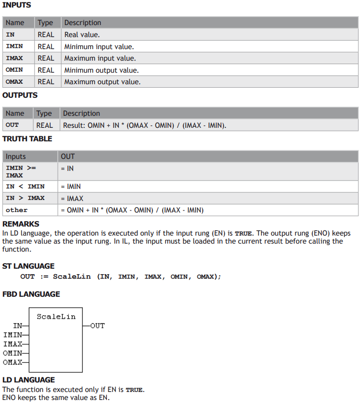
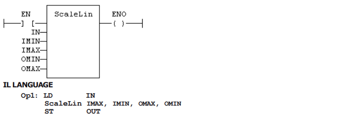
STANDARD MATHEMATICAL FUNCTIONS