
5. MOTION PERFECT V3
Introduction to Motion Perfect 3
Motion Perfect 3 is an Microsoft Windows™ based application for the PC, designed to be used in conjunction with Trio Motion Technology’s Series 4 Motion Coordinator range of multi-tasking motion controllers.
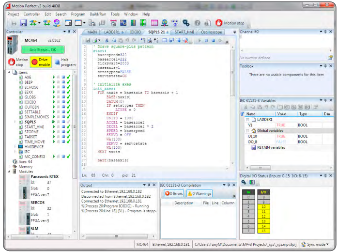
Motion Perfect 3 provides the user with an easy to use Windows based interface for controller configuration, rapid application development, and run-time diagnostics of processes running on the Motion Coordinator.
System Requirements
PC
A PC with the following specifications is required to run Motion Perfect 3:
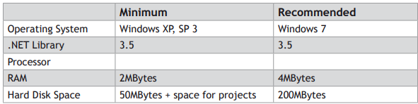
Due to limitations in some of the third party libraries used, Motion Perfect 3 is only available as a 32 bit application. This will however run on 64 bit Microsoft Windows™.
It is recommended that your copy of Microsoft Windows™ has all current service packs and updates applied.
CONTROLLER
The requirements for a controller are different depending on the mode of connection.
DIRECT MODE
To connect in Direct Mode the controller can be almost any Trio series 2, 3 or 4 Motion Coordinator.
TOOL MODE / SYNC MODE
To connect in Tool Mode or Sync Mode the controller must be a Trio series 4 Motion Coordinator running system firmware version 2.0177 or later.
Operating Modes
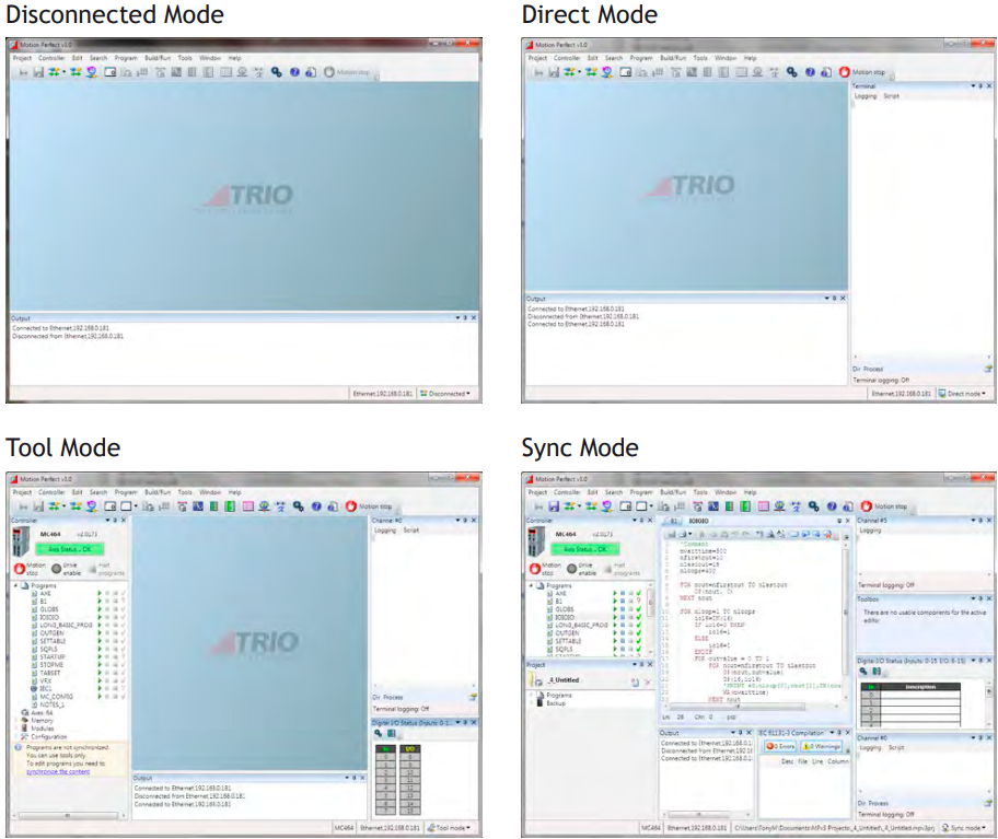
Motion Perfect 3 has four operating modes:
• Disconnected
• Direct
• Tool Mode
• Sync Mode
The current connection mode is displayed on the right of the status bar at the bottom of Motion Perfect’s main window.
 DISCONNECTED
Not connected to a controller. All tools are closed and no communications ports are open.
 DIRECT MODE
A direct connection is made to a controller allowing a Terminal tool to be used for direct interaction with the command line on the controller.
 TOOL MODE
A multichannel connection is made to a controller allowing the monitoring tools within Motion Perfect to be used. This mode allows the user to see a list of the programs on the controller (so that they can be started and stopped) but does not allow editing of any of the programs.
 SYNC MODE
A multichannel connection is made to a controller and a local project on the PC is opened. The contents of the controller and the project are synchronized so that the local copy of all programs matches those on the controller. All of Motion Perfect’s tools are available and programs can be edited. The synchronization process can involve deleting programs or copying them from the controller to the PC of vice versa.
A connection (direct or multichannel) to a controller consists of a single TCP/IP socket connection over Ethernet
Main Window
The “Main Window” is the main user interface of Motion Perfect 3. It acts as a desktop for displaying all controls needed to interact with a single controller.
Because the tools available to the user are different for each operating mode the Main Window tends to take on a different appearance for each mode.
In all operation modes the user has access to the Main Menu and Main Toolbar for commands, although the commands available will depend on the operation mode.
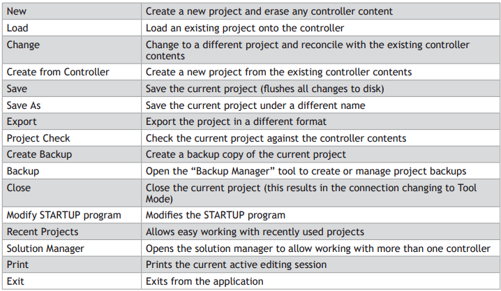
PROJECT
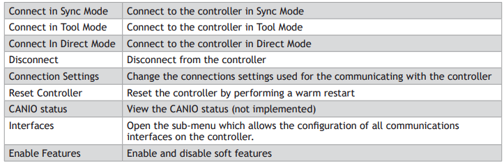
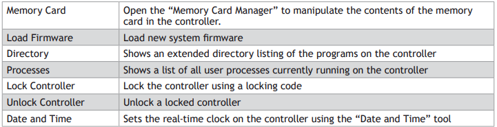
CONTROLLER
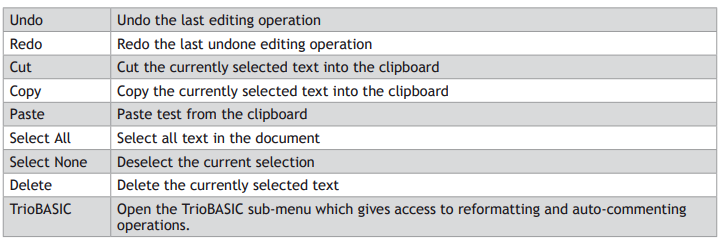
EDIT
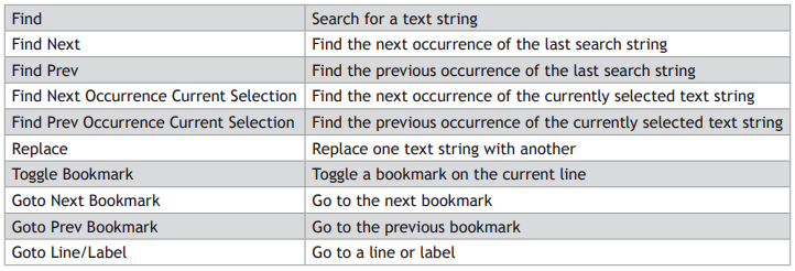
SEARCH
All search commands apply to the current active editing session

PROGRAM

BUILD/RUN
The commands I n this sub-menu operate on the program open in the current active editing session.
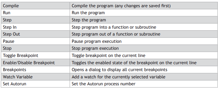
The availability of the commands in the Build/Run sub-menu depends on the type or program being edited and the run state of the program.
TOOLS
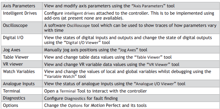
WINDOW
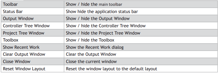
HELP


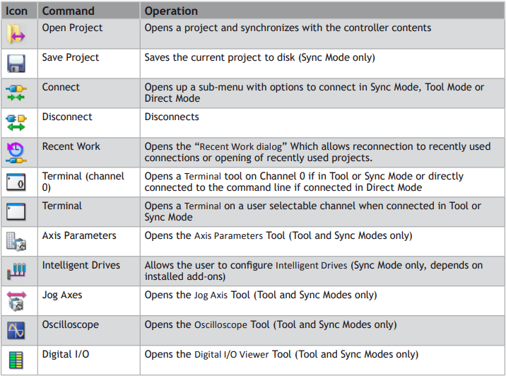
Main Toolbar

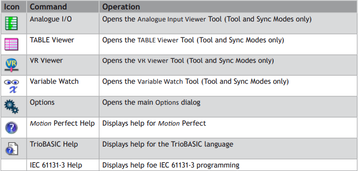
The Main Toolbar gives the user quick access to Motion Perfect’s main tools and functions.
Controller Tree
The controller tree can be displayed when Motion Perfect is operating in “Tool Mode” or in “Sync Mode”. It contains information about the controller connected to Motion Perfect and its contents.
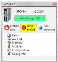
The tree consists of a header section and the tree body.
TREE HEADER
The tree header contains basic information about the controller plus some important controls. The top of the header contains a pictorial representation of the controller, the controller model (MC464 in the case above), the system software version number and an “Axis Status” control. The bottom of the header contains three button controls: “Motion Stop”, “Drive Enable” and “Halt Programs”
CONTROLLER INFORMATION
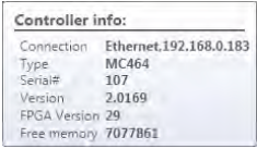
The controller is shown as an icon to the left of the header. The controller model and system software version are displayed towards the top of the header. If the mouse cursor is moved over the icon a tooltip is displayed giving some basic information about the controller.
“AXIS STATUS” CONTROL
This control shows the error status of the controller. It is a passive control when there is no error and is coloured green. When an error occurs the control becomes coloured red and then acts as a button which, when clicked, will clear the error on the controller.
Some errors, notably hardware errors, cannot be cleared by clicking the “Axis Status” button.
“MOTION STOP” BUTTON
Clicking on the “Motion Stop” button stops all currently running programs and empties all the move buffers on the controller causing all motion to stop. Its action is similar to an “Emergency Stop” button but, as it is implemented in software, it is less reliable that a properly implemented hardware emergency stop.
It is important that a proper hardware emergency stop is implemented on any system. This button must not be used as a substitute.
“DRIVE ENABLE” BUTTON
Clicking on this button toggles the state of the drive enable (watchdog output) on the controller. When drives are enabled the background of the button is coloured yellow.
“HALT PROGRAMS” BUTTON
Clicking on this button halts all currently running programs but does not stop and current or buffered moves.
Use the “Motion Stop” button if you want to stop the motion as well as the programs.
TREE BODY
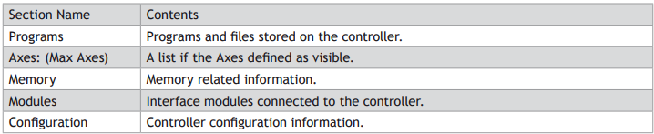
The body of the tree contains information in several expandable sections:
PROGRAMS
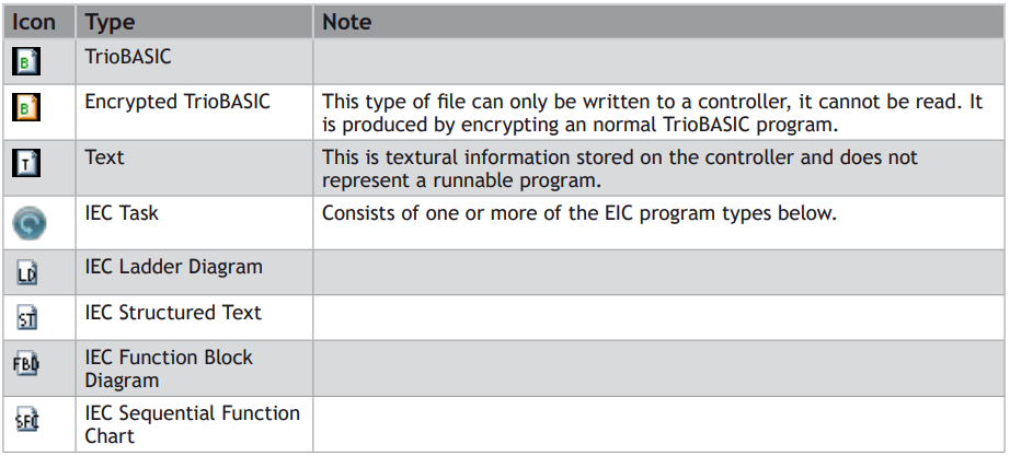
These are the programs and files stored on the controller. The following types of item can be stored on the controller:
• TrioBASIC program
• Text file
• MC _ CONFIG program (one only)
• HMI project (not available on all controllers) containing one or more HMI page definitions.
• IEC 61131-3 project (not available on all controllers) containing one or more programs in one or more of the IEC 61131-3 defined program types.
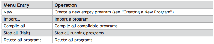
The “Programs” item in the tree has a context menu to allow creation of programs and some operations on all programs as follows:
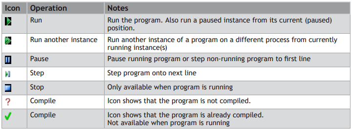
The program entries in the tree allow the user to run, pause, stop and compile the program by means of a set if icons after each program entry.
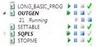
When a program is running it has an extra entry in the tree representing the running instance, showing the process number.
AXES: (MAX AXES)
The value of Max Axes is the total number of axes available on the controller, both real and virtual.
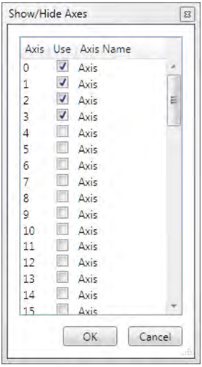
When expanded the list of axes shown is that specified by the user. To specify which axes are to be shown, right click on axes and select “Shaw/Hide Axes…” to display the “Show/Hide Axes” dialog and select which axes to display.
MEMORY
This shows various memory related items as follows:
VR
The maximum number of VR variables allowed. Double clicking on this launches the VR Viewer tool.
TABLE
The size (in values) of the TABLE memory area. Double clicking on this launches the Table Viewer Tool.
LOCAL VARIABLES
Double clicking on this launcher the variable viewer tool.
GLOBALS
Currently not used.
FREE PROGRAM SPACE
The number of bytes of unused memory available for storing programs in.
MODULES
This give a list of the modules connected to a controller. Currently this only supports the local modules of a modular controller such as the MC464.
CONFIGURATION
Shows the current controller configuration and allows the user to change some user configurable features.
Project Tree
The project tree can be displayed when Motion Perfect is operating in “Sync Mode”. It contains information about the current project Motion Perfect.
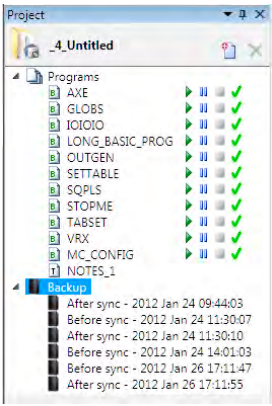
The tree consists of a header section and the tree body.
TREE HEADER
The tree header contains basic information about the project plus some important controls. The header contains a project icon, the project name, a “New Program” button and a “Delete Item” button.
“MOTION STOP” BUTTON
Clicking on the “Motion Stop” button stops all currently running programs and empties all the move buffers on the controller causing all motion to stop. Its action is similar to an “Emergency Stop” button but, as it is implemented in software, it is less reliable that a properly implemented hardware emergency stop.
It is important that a proper hardware emergency stop is implemented on any system. This button must not be used as a substitute.

PROGRAMS
This section duplicates the functionality of the “Programs” section in the “Controller Tree”
BACKUPS
Every time Motion Perfect synchronizes with a project a backup of the project is made before and after the synchronization operation (the backup after is only made if synchronization has been successful). The tree contains a list of the backups currently stored on the PC.
The “Backups” item in the tree has a context menu as follows:

Each backup entry also has a context menu as follows:

Output Window
The “Output Window” displays the status messages received from the controller.
Solutions
In order to handle systems which contain more than one controller Motion Perfect uses a “Solution” to manage the connections to more than one controller and their associated projects. The solution defines a list of controllers included in the solution. For each controller it also defines a connection used to communicate with the controller and a project associated with it. No two controllers can be associated with the same project. The user can create and edit a solution using the Solution Manager.
SOLUTION MANAGER
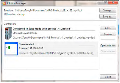
The Solution Manager is used to manage a collection of projects (solution) which are used for applications containing multiple controllers. In single applications which contain only one project, Motion Perfect uses a default solution so that the user does not need to use the solution manager.
The default solution cannot contain more than one project.
CONTROLS
LOAD ON STARTUP CHECKBOX
If checked, the solution manager and the current solution will be loaded when Motion Perfect is started.
CHANGE SOLUTION BUTTON
Change to a different solution.
SAVE SOLUTION AS BUTTON
Save the current solution under a new name
ADD CONTROLLER BUTTON
Add a controller (connection) to the solution.
REMOVE CONTROLLER BUTTON
Remove the currently selected controller (connection) from the solution
OPEN WINDOW BUTTON
Open a window for the currently selected controller
CLOSE WINDOW BUTTON
Close the open window for the currently selected controller
CLOSE BUTTON
Close the “Solution Manager” window
CREATING A SOLUTION
• Create a project for one controller as normal.
• Open the “Solution Manager” from the Project section of the main menu. This will display the existing project as part of the “Default Solution”.
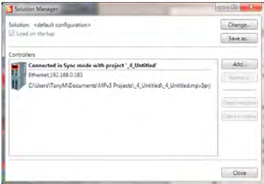
• Click on the “Add” button. A warning about multiple controllers will be displayed.
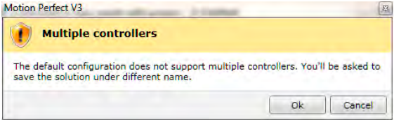
• Clicking on the “OK” button will cause the “Connection Dialog” to be displayed. Configure an appropriate connection for another controller. On closing the “Connection Dialog” you will be prompted to save the solution. A desktop window will appear for the connection to the new controller.
• To associate a project with the new controller, attempt to connect to it in Sync Mode (this may happen automatically depending on the stored state of the connection). The “Controller Project Dialog” will be displayed to allow this.
Project
A Motion Perfect project contains a set of programs and settings which represents the contents of the controller for a given application. Al files relating to a project are stored in a single directory on the PC this is known as the project directory.
PROJECT DIRECTORY
The files contained in the project directory will depend on the programs used in the project. There are three main files in the project directory which all have the same name as the project directory but have different file extensions.
PROJECT FILE (EXTENSION “MPV3PRJ”)
This contains a definition of the contents of the project (programs) and any customization such as axis names.
DESKTOP FILE (EXTENSION “MPV3DSK”)
This contains the desktop layout used when Motion Perfect is connected in sync mode to the controller.
TOOL INTERNAL CONDITIONS (EXTENSION “MPV3IC”)
This contains the internal state of each open tool window when Motion Perfect is connected in sync mode to the controller.
PROGRAM FILES
Program files are also stored in the project directory. The type of each file can be determined by its file extension the most important being .BAS which is used for TioBASIC programs. Each TrioBASIC program may also have a .PRG file of the same name which specifies editor/debugger settings for the program. Some complex types of program (usually handled by an add-in) can have sub-directories which contain their data as well as one or more files in the project directory.
There is also a “Backup” sub-directory in which backups of the project are stored.
WARNING
Although many of the files which form part of the project are text files the user should not edit them directly using a text editor as this may cause compatibility problems between the project and the controller. All changes should be made using Motion Perfect.
Project Check
A project check is performed every time Motion Perfect connects in “Sync Mode” and if the user initiates a project check from the main menu. The programs in the project are checked against those on the controller and if there are any differences the “Resolve Program Differences” dialog is displayed so the user can resolve the differences.
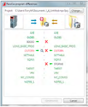
RESOLVING DIFFERENCES
The “Resolve Program Differences” dialog can perform several different operations to resolve differences.
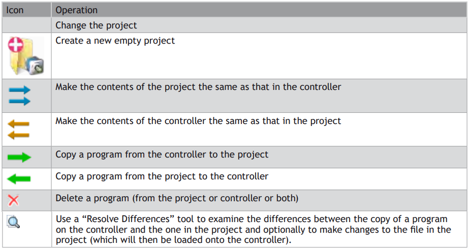
The synchronization operation is carried out when the user clicks on the “Synchronize” button which is only enabled
Once a set of operations has been selected which will resolve all differences.
The synchronization operations available depend on the types of program in the project and on the controller.
It is possible that a program copied from the project onto the controller will still cause a project check failure if the controller supports different keywords to those supported by the controller on which the program was written. This problem can be resolved by saving the copy on the controller into the project or manually resolving the differences.
PROBLEMS LOADING PROGRAMS
Even though it appears that differences can be resolved by loading the project or some of its programs onto the controller it is still possible to get a mismatch between the controller and the project. This is usually due to different TrioBASIC keywords being supported on the controller to those supported on the controller on which the program was written. This can cause variables to become keywords, keywords to become variables or keywords to change.
All the letters in a keyword are always upper case whereas all the letters in a variable name are always lower case.
When this occurs a warning dialog will be displayed to show that the controller has made changes to the program.
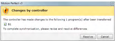
The user now has the choice of resolving the differences using the program modifications dialog or cancelling. If you cancel it is then possible to resolve differences by doing another
project check and manually resolving the differences using the “Resolve Differences” tool.
MODIFICATIONS DIALOG
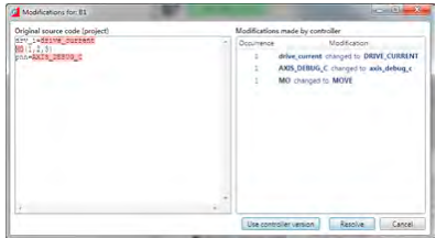
This shows the original program source (on the PC) on the left and the changes made to it on the right. The user can resolve the differences by either using the controller version of the program or by clicking on the “Resolve” button which steps through the differences to allow the used to make a decision for each one using the “Resolve” dialog.
RESOLVE DIALOG
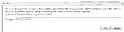
The new value for the word to resolve is automatically filled in using the value obtained from the controller.
The user can type any valid keyword, variable name, or number to replace the word in the source file.
Clicking on “OK” makes the change and clicking on “Cancel” cancels the whole resolution process.
Program Types
Motion Perfect supports several different program types as follows:
Creating a New Program
A new program can be created by Selecting “Program / New” from the main menu or by selecting “New” from the “Programs” item in the controller menu.
The “New Program” dialog is launched. This allows the user to select the type of program required and enter a name. Clicking on “OK” will create the new program.
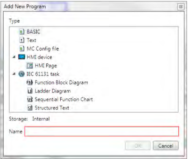
This is only available while connected in Sync Mode.
Program Editor
The Program Editor is used to edit TrioBASIC program files and text files which form part of a Motion Perfect project and to provide debugging facilities for TrioBASIC programs.
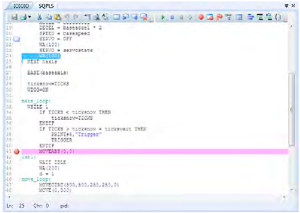
Editing a TrioBASIC program
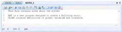
Editing a text file
The editor performs in a similar way to most modern text editors. Editing functions are available for all supported program/file types, debugging functions and special formatting functions are only available when editing a TrioBASIC program.
EDITING FUNCTIONS
Editing functions are available from the Edit Toolbar:

The available editing functions are as follows and apply to the current program/file being edited:
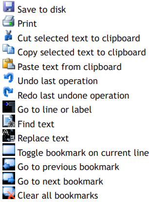
Some editing functions are available on the Editor Context Menu.
DEBUGGING FUNCTIONS
Debugging functions are available from the Debug Toolbar

The available debugging functions are as follows and apply to the current program being edited:
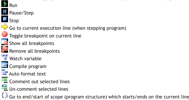
Some debugging functions are available on the Editor Context Menu.
OPERATION
Although the editor appears to work like any other text editor it has one main difference. Each line of text is sent to the connected controller as it is entered or edited. This means that the controller is always kept up to date with changes. The controller is used to perform syntax checking when editing a TrioBASIC program, removing any possibility that the syntax is checked against out of date rules. All compiling and debugging operations are also carried out on the actual controller.
The general appearance of the editor can be customized using the Program Editor pages in the main Options Dialog.
WATCHING VARIABLES
The values of variables can be watched while a program is running or being stepped. This is done using the “Watch Variables” tool, which can be used to monitor both local and VR variables.
To add a variable to the watch list, select the variable name (including index if a VR) in the editor, then select “Watch Variable” from the context menu or click on the icon in the editor toolbar. Alternatively, if the “Watch Variables” tool is open, select the variable name then drag and drop it into the “Watch Variables” tool.