
5. MOTION PERFECT V3
Introduction to Motion Perfect 3
Motion Perfect 3 is an Microsoft Windows™ based application for the PC, designed to be used in conjunction with Trio Motion Technology’s Series 4 Motion Coordinator range of multi-tasking motion controllers.
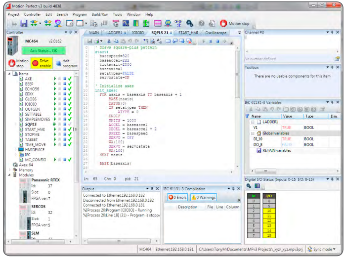
Motion Perfect 3 provides the user with an easy to use Windows based interface for controller configuration, rapid application development, and run-time diagnostics of processes running on the Motion Coordinator.
System Requirements
PC
A PC with the following specifications is required to run Motion Perfect 3:
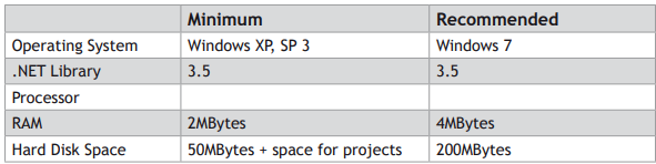
Due to limitations in some of the third party libraries used, Motion Perfect 3 is only available as a 32 bit application. This will however run on 64 bit Microsoft Windows™.
It is recommended that your copy of Microsoft Windows™ has all current service packs and updates applied.
CONTROLLER
The requirements for a controller are different depending on the mode of connection.
DIRECT MODE
To connect in Direct Mode the controller can be almost any Trio series 2, 3 or 4 Motion Coordinator.
TOOL MODE / SYNC MODE
To connect in Tool Mode or Sync Mode the controller must be a Trio series 4 Motion Coordinator running system firmware version 2.0177 or later.
Operating Modes
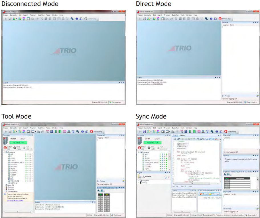
Motion Perfect 3 has four operating modes:
• Disconnected
• Direct
• Tool Mode
• Sync Mode
The current connection mode is displayed on the right of the status bar at the bottom of Motion Perfect’s main window.
 DISCONNECTED
Not connected to a controller. All tools are closed and no communications ports are open.
 DIRECT MODE
A direct connection is made to a controller allowing a Terminal tool to be used for direct interaction with the command line on the controller.
 TOOL MODE
A multichannel connection is made to a controller allowing the monitoring tools within Motion Perfect to be used. This mode allows the user to see a list of the programs on the controller (so that they can be started and stopped) but does not allow editing of any of the programs.
 SYNC MODE
A multichannel connection is made to a controller and a local project on the PC is opened. The contents of the controller and the project are synchronized so that the local copy of all programs matches those on the controller. All of Motion Perfect’s tools are available and programs can be edited. The synchronization process can involve deleting programs or copying them from the controller to the PC of vice versa.
A connection (direct or multichannel) to a controller consists of a single TCP/IP socket connection over Ethernet
Main Window
The “Main Window” is the main user interface of Motion Perfect 3. It acts as a desktop for displaying all controls needed to interact with a single controller.
Because the tools available to the user are different for each operating mode the Main Window tends to take on a different appearance for each mode.
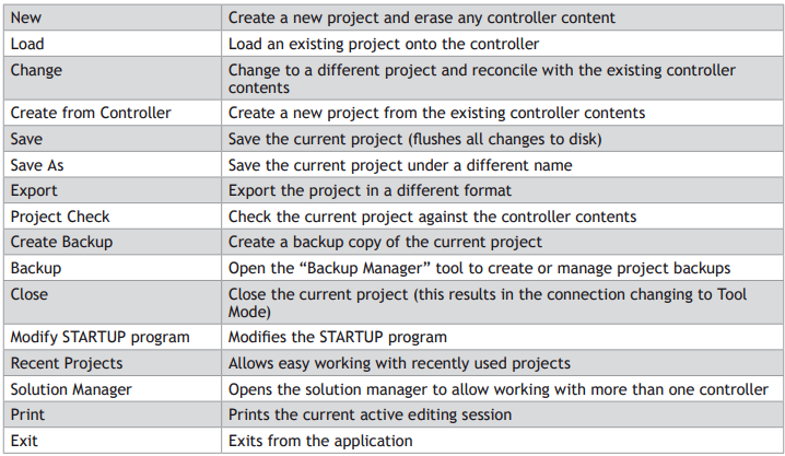
In all operation modes the user has access to the Main Menu and Main Toolbar for commands, although the commands available will depend on the operation mode.
PROJECT
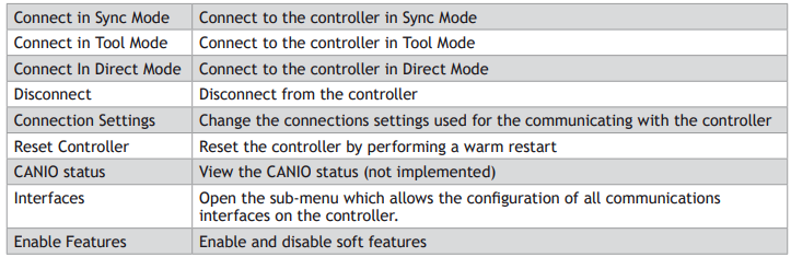
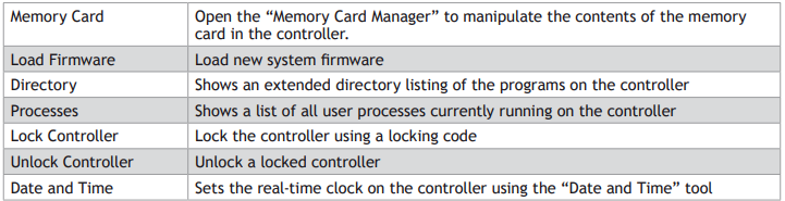
CONTROLLER
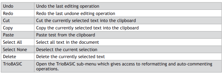
EDIT
SEARCH
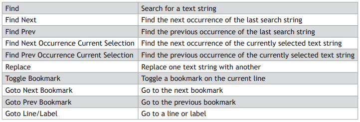
All search commands apply to the current active editing session

PROGRAM

BUILD/RUN
The commands I n this sub-menu operate on the program open in the current active editing session.
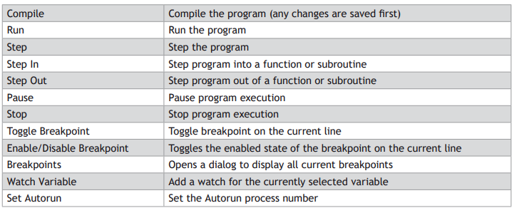
The availability of the commands in the Build/Run sub-menu depends on the type or program being edited and the run state of the program.
TOOLS
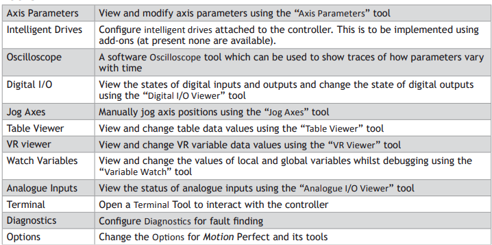
WINDOW
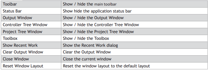
HELP


Main Toolbar

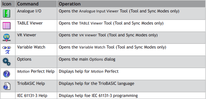
The Main Toolbar gives the user quick access to Motion Perfect’s main tools and functions.
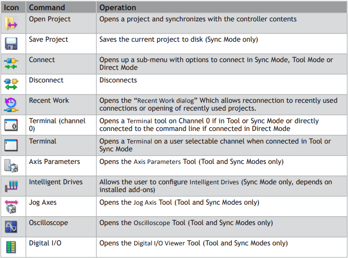
Controller Tree
The controller tree can be displayed when Motion Perfect is operating in “Tool Mode” or in “Sync Mode”. It contains information about the controller connected to Motion Perfect and its contents.
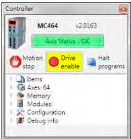
The tree consists of a header section and the tree body.
TREE HEADER
The tree header contains basic information about the controller plus some important controls. The top of the header contains a pictorial representation of the controller, the controller model (MC464 in the case above), the system software version number and an “Axis Status” control. The bottom of the header contains three button controls: “Motion Stop”, “Drive Enable” and “Halt Programs”
CONTROLLER INFORMATION
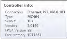
The controller is shown as an icon to the left of the header. The controller model and system software version are displayed towards the top of the header. If the mouse cursor is moved over the icon a tooltip is displayed giving some basic information about the controller.
“AXIS STATUS” CONTROL
This control shows the error status of the controller. It is a passive control when there is no error and is coloured green. When an error occurs the control becomes coloured red and then acts as a button which, when clicked, will clear the error on the controller.
Some errors, notably hardware errors, cannot be cleared by clicking the “Axis Status” button.
“MOTION STOP” BUTTON
Clicking on the “Motion Stop” button stops all currently running programs and empties all the move buffers on the controller causing all motion to stop. Its action is similar to an “Emergency Stop” button but, as it is implemented in software, it is less reliable that a properly implemented hardware emergency stop.
It is important that a proper hardware emergency stop is implemented on any system. This button must not be used as a substitute.
“DRIVE ENABLE” BUTTON
Clicking on this button toggles the state of the drive enable (watchdog output) on the controller. When drives are enabled the background of the button is coloured yellow.
“HALT PROGRAMS” BUTTON
Clicking on this button halts all currently running programs but does not stop and current or buffered moves.
Use the “Motion Stop” button if you want to stop the motion as well as the programs.
TREE BODY
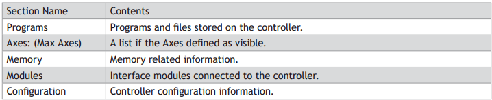
The body of the tree contains information in several expandable sections:
PROGRAMS
These are the programs and files stored on the controller. The following types of item can be stored on the controller:
• TrioBASIC program
• Text file
• MC _ CONFIG program (one only)
• HMI project (not available on all controllers) containing one or more HMI page definitions.
• IEC 61131-3 project (not available on all controllers) containing one or more programs in one or more of the IEC 61131-3 defined program types.
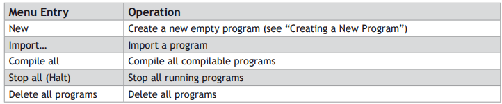
The “Programs” item in the tree has a context menu to allow creation of programs and some operations on all programs as follows:
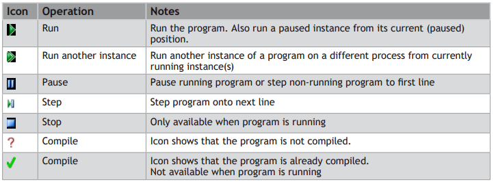
The program entries in the tree allow the user to run, pause, stop and compile the program by means of a set if icons after each program entry.
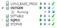
When a program is running it has an extra entry in the tree representing the running instance, showing the process number.
AXES: (MAX AXES)
The value of Max Axes is the total number of axes available on the controller, both real and virtual.
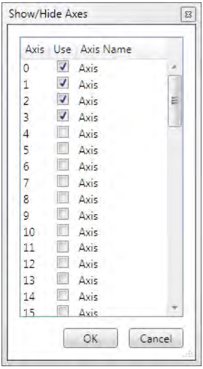
When expanded the list of axes shown is that specified by the user. To specify which axes are to be shown, right click on axes and select “Shaw/Hide Axes…” to display the “Show/Hide Axes” dialog and select which axes to display.
MEMORY
This shows various memory related items as follows:
VR
The maximum number of VR variables allowed. Double clicking on this launches the VR Viewer tool.
TABLE
The size (in values) of the TABLE memory area. Double clicking on this launches the Table Viewer Tool.
LOCAL VARIABLES
Double clicking on this launcher the variable viewer tool.
GLOBALS
Currently not used.
FREE PROGRAM SPACE
The number of bytes of unused memory available for storing programs in.
MODULES
This give a list of the modules connected to a controller. Currently this only supports the local modules of a modular controller such as the MC464.
CONFIGURATION
Shows the current controller configuration and allows the user to change some user configurable features.
Project Tree
The project tree can be displayed when Motion Perfect is operating in “Sync Mode”. It contains information about the current project Motion Perfect.
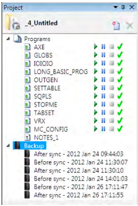
The tree consists of a header section and the tree body.
TREE HEADER
The tree header contains basic information about the project plus some important controls. The header contains a project icon, the project name, a “New Program” button and a “Delete Item” button.
“MOTION STOP” BUTTON
Clicking on the “Motion Stop” button stops all currently running programs and empties all the move buffers on the controller causing all motion to stop. Its action is similar to an “Emergency Stop” button but, as it is implemented in software, it is less reliable that a properly implemented hardware emergency stop.
It is important that a proper hardware emergency stop is implemented on any system. This button must not be used as a substitute.

PROGRAMS
This section duplicates the functionality of the “Programs” section in the “Controller Tree”
BACKUPS
Every time Motion Perfect synchronizes with a project a backup of the project is made before and after the synchronization operation (the backup after is only made if synchronization has been successful). The tree contains a list of the backups currently stored on the PC.
The “Backups” item in the tree has a context menu as follows:

Each backup entry also has a context menu as follows:

Output Window
The “Output Window” displays the status messages received from the controller.
Solutions
In order to handle systems which contain more than one controller Motion Perfect uses a “Solution” to manage the connections to more than one controller and their associated projects. The solution defines a list of controllers included in the solution. For each controller it also defines a connection used to communicate with the controller and a project associated with it. No two controllers can be associated with the same project. The user can create and edit a solution using the Solution Manager.
SOLUTION MANAGER
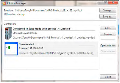
The Solution Manager is used to manage a collection of projects (solution) which are used for applications containing multiple controllers. In single applications which contain only one project, Motion Perfect uses a default solution so that the user does not need to use the solution manager.
The default solution cannot contain more than one project.
CONTROLS
LOAD ON STARTUP CHECKBOX
If checked, the solution manager and the current solution will be loaded when Motion Perfect is started.
CHANGE SOLUTION BUTTON
Change to a different solution.
SAVE SOLUTION AS BUTTON
Save the current solution under a new name
ADD CONTROLLER BUTTON
Add a controller (connection) to the solution.
REMOVE CONTROLLER BUTTON
Remove the currently selected controller (connection) from the solution
OPEN WINDOW BUTTON
Open a window for the currently selected controller
CLOSE WINDOW BUTTON
Close the open window for the currently selected controller
CLOSE BUTTON
Close the “Solution Manager” window
CREATING A SOLUTION
• Create a project for one controller as normal.
• Open the “Solution Manager” from the Project section of the main menu. This will display the existing project as part of the “Default Solution”.
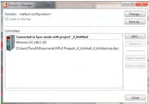
• Click on the “Add” button. A warning about multiple controllers will be displayed.
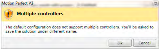
• Clicking on the “OK” button will cause the “Connection Dialog” to be displayed. Configure an appropriate connection for another controller. On closing the “Connection Dialog” you will be prompted to save the solution. A desktop window will appear for the connection to the new controller.
• To associate a project with the new controller, attempt to connect to it in Sync Mode (this may happen automatically depending on the stored state of the connection). The “Controller Project Dialog” will be displayed to allow this.
Project
A Motion Perfect project contains a set of programs and settings which represents the contents of the controller for a given application. Al files relating to a project are stored in a single directory on the PC this is known as the project directory.
PROJECT DIRECTORY
The files contained in the project directory will depend on the programs used in the project. There are three main files in the project directory which all have the same name as the project directory but have different file extensions.
PROJECT FILE (EXTENSION “MPV3PRJ”)
This contains a definition of the contents of the project (programs) and any customization such as axis names.
DESKTOP FILE (EXTENSION “MPV3DSK”)
This contains the desktop layout used when Motion Perfect is connected in sync mode to the controller.
TOOL INTERNAL CONDITIONS (EXTENSION “MPV3IC”)
This contains the internal state of each open tool window when Motion Perfect is connected in sync mode to the controller.
PROGRAM FILES
Program files are also stored in the project directory. The type of each file can be determined by its file extension the most important being .BAS which is used for TioBASIC programs. Each TrioBASIC program may also have a .PRG file of the same name which specifies editor/debugger settings for the program. Some complex types of program (usually handled by an add-in) can have sub-directories which contain their data as well as one or more files in the project directory.
There is also a “Backup” sub-directory in which backups of the project are stored.
WARNING
Although many of the files which form part of the project are text files the user should not edit them directly using a text editor as this may cause compatibility problems between the project and the controller. All changes should be made using Motion Perfect.
Project Check
A project check is performed every time Motion Perfect connects in “Sync Mode” and if the user initiates a project check from the main menu. The programs in the project are checked against those on the controller and if there are any differences the “Resolve Program Differences” dialog is displayed so the user can resolve the differences.
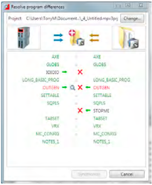
RESOLVING DIFFERENCES
The “Resolve Program Differences” dialog can perform several different operations to resolve differences.
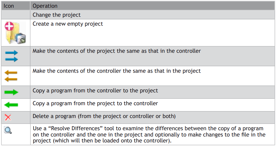
The synchronization operation is carried out when the user clicks on the “Synchronize” button which is only enabled
Once a set of operations has been selected which will resolve all differences.
The synchronization operations available depend on the types of program in the project and on the controller.
It is possible that a program copied from the project onto the controller will still cause a project check failure if the controller supports different keywords to those supported by the controller on which the program was written. This problem can be resolved by saving the copy on the controller into the project or manually resolving the differences.
PROBLEMS LOADING PROGRAMS
Even though it appears that differences can be resolved by loading the project or some of its programs onto the controller it is still possible to get a mismatch between the controller and the project. This is usually due to different TrioBASIC keywords being supported on the controller to those supported on the controller on which the program was written. This can cause variables to become keywords, keywords to become variables or keywords to change.
All the letters in a keyword are always upper case whereas all the letters in a variable name are always lower case.
When this occurs a warning dialog will be displayed to show that the controller has made changes to the program.
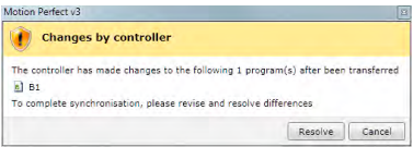
The user now has the choice of resolving the differences using the program modifications dialog or cancelling. If you cancel it is then possible to resolve differences by doing another
project check and manually resolving the differences using the “Resolve Differences” tool.
MODIFICATIONS DIALOG
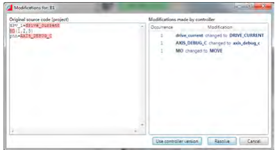
This shows the original program source (on the PC) on the left and the changes made to it on the right. The user can resolve the differences by either using the controller version of the program or by clicking on the “Resolve” button which steps through the differences to allow the used to make a decision for each one using the “Resolve” dialog.
RESOLVE DIALOG
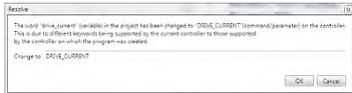
The new value for the word to resolve is automatically filled in using the value obtained from the controller.
The user can type any valid keyword, variable name, or number to replace the word in the source file.
Clicking on “OK” makes the change and clicking on “Cancel” cancels the whole resolution process.
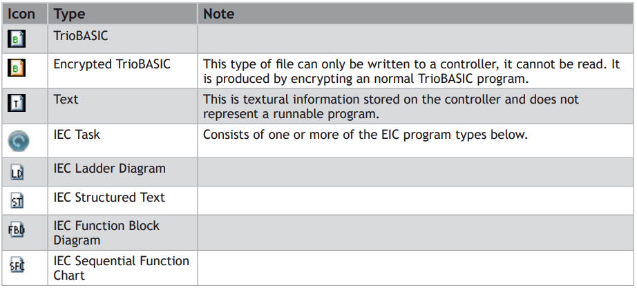
Program Types
Motion Perfect supports several different program types as follows:
Creating a New Program
A new program can be created by Selecting “Program / New” from the main menu or by selecting “New” from the “Programs” item in the controller menu.
The “New Program” dialog is launched. This allows the user to select the type of program required and enter a name. Clicking on “OK” will create the new program.
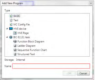
This is only available while connected in Sync Mode.
Program Editor
The Program Editor is used to edit TrioBASIC program files and text files which form part of a Motion Perfect project and to provide debugging facilities for TrioBASIC programs.
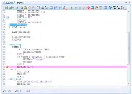
Editing a TrioBASIC program
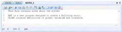
Editing a text file
The editor performs in a similar way to most modern text editors. Editing functions are available for all supported program/file types, debugging functions and special formatting functions are only available when editing a TrioBASIC program.
EDITING FUNCTIONS
Editing functions are available from the Edit Toolbar:

The available editing functions are as follows and apply to the current program/file being edited:
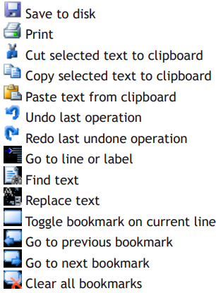
Some editing functions are available on the Editor Context Menu.
DEBUGGING FUNCTIONS
Debugging functions are available from the Debug Toolbar

The available debugging functions are as follows and apply to the current program being edited:
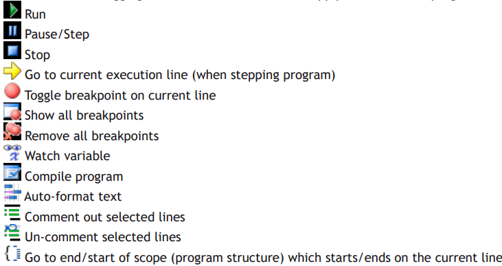
Some debugging functions are available on the Editor Context Menu.
OPERATION
Although the editor appears to work like any other text editor it has one main difference. Each line of text is sent to the connected controller as it is entered or edited. This means that the controller is always kept up to date with changes. The controller is used to perform syntax checking when editing a TrioBASIC program, removing any possibility that the syntax is checked against out of date rules. All compiling and debugging operations are also carried out on the actual controller.
The general appearance of the editor can be customized using the Program Editor pages in the main Options Dialog.
WATCHING VARIABLES
The values of variables can be watched while a program is running or being stepped. This is done using the “Watch Variables” tool, which can be used to monitor both local and VR variables.
To add a variable to the watch list, select the variable name (including index if a VR) in the editor, then select “Watch Variable” from the context menu or click on the icon in the editor toolbar. Alternatively, if the “Watch Variables” tool is open, select the variable name then drag and drop it into the “Watch Variables” tool.
Connection Dialogue
The connection dialog allows the user to configure a communications interface in order to connect to a controller. Ethernet, Serial, PCI and USB interfaces are supported by Motion Perfect. It is possible to select a communications interface and configure it manually or choose from recently used connections.
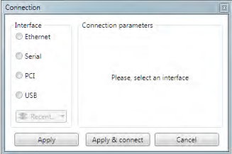
RECENT CONNECTIONS
To choose a recent connection, click on the “Recent” button and choose a connection from the drop-down list.
ETHERNET
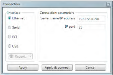
It is possible to change the server IP address (IP address of the controller) and the IP port on which it communicates.
By default a controller will expect a connection from Motion Perfect to be made on port 23.
SERIAL
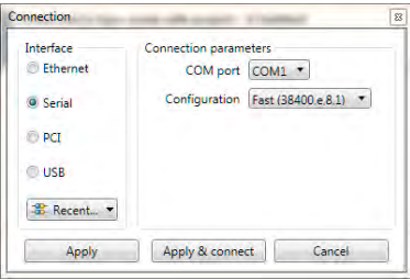
It is possible to select the COM interface and the configuration (serial link parameters) from a choice of Slow (9600,e,7,2) and Fast (38400,e,8,1), these being the default settings for series 2 & 3 Trio Motion Coordinators.
PCI
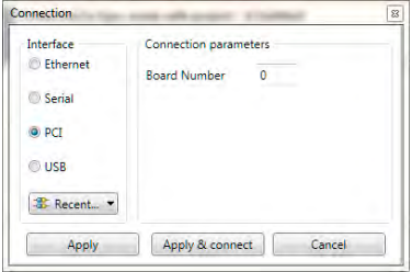
It is possible to select the board number. Board numbers are allocated when the PC is started up and is enumerated between 0 and the one less than the number of Trio PCI cards connected.
USB
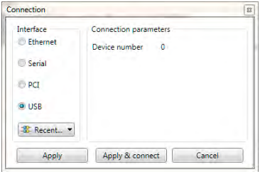
It is possible to select the device number. Device numbers are allocated when the PC is started up and when devices are added or removed. It is normally enumerated between 0 and the one less than the number of Trio USB devices connected. Because of the nature of the internal scanning process which enumerates USB devices and the possibility that devices are added or removed after the initial scan has completed, a given device may not always have the same device number.
It is recommended that only one Trio USB device be connected to a PC at any one time.
Initial Connection
To make the initial connection to a controller:
1. Make sure that your controller is powered up and connected to the computer
2. Start Motion Perfect 3. Once it has started up the initial screen should be displayed.
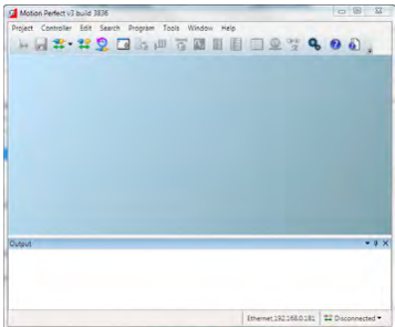
3. Select “ Connect in Direct mode” from the “Controller” menu. As Motion Perfect has not been connected before the “Connection Error” dialog will be displayed.
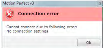
4. Click on the “OK” button. The “Connection” dialog will then be displayed.
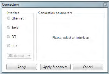
5. Select the communications interface used by your controller (this will usualyl be Ethernet), then enter it’s parameters. For an Ethernet connection this will be the IP address (defailt 192.168.0.250) and the TCP port (default 23).
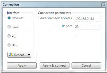
6. Click on the “Apply & Connect” button. The “Connect” will close and Motion Perfect will go into Direct Mode with an active Terminal tool.
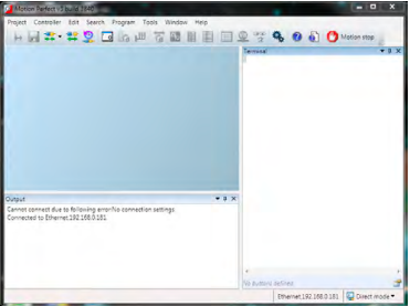
Motion Perfect will remember the last used connection parameters and will automatically try and use them when reconnecting in Direct Mode in the future.
Recent Work Dialogue
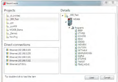
The “Recent Work Dialog” lists recently used projects and connections to allow the user to quickly switch to a different, recently used, project or connection. When a project is selected the “Details” pane on the right of the dialog shows the contents of the project, otherwise, if a connection is selected it shows connection details. Clicking on the load button will load the selected project or connect using the selected connection.
Tools
Motion Perfect 3 has several tools which are used to monitor the controller and interact with it. Some tools are built into Motion Perfect, others are implemented as add-ons. The add-on mechanism allows the easy addition of extra tools in the future. Most tools are available in both “Tool Mode” and “Sync Mode”.
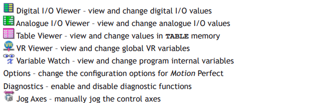
BUILT-IN TOOLS

ADD-ON TOOLS

Terminal
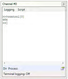
The “Terminal” tool allows the user to interact directly with the controller, either with the command line (channel 0) or with user programs (channel 5, 6 or 7). Characters typed on the keyboard are sent to the controller and characters output by the controller are displayed in the terminal window.
TERMINAL MENU
The menu controls terminal logging and scripting.
TERMINAL LOGGING
When logging is active all the data displayed on the terminal is also written to a file. The name of the log file is displayed in the status bar at the bottom of the terminal window.
TERMINAL SCRIPTING (ONLY AVAILABLE ON CHANNEL 0)
INTRODUCTION
Motion Perfect has built in support for simple terminal scripting. This allows the user to write files of commands and then send the file contents to the controller in a single operation. In addition to the commands to be sent to the controller there are some extra commands which are used by Motion Perfect to control the running of the script.
INTERACTION WITH THE CONTROLLER
Command lines are sent to the controller one at a time in sequence. Motion Perfect sends a command then waits to receive a prompt (>>) before sending the next one.
To not wait for a prompt put the two character sequence \& on the end of the line. These extra characters are not sent to the controller.
SCRIPT COMMANDS
Script commands control the running of the script. All script commands start with two colons. The following commands are valid:

e.g.:
::Timeout 55
sets the timeout to 55 seconds
TESTS
Special support has been added in order to enable the use of scripts for testing purposes. The response from a command can be tested by Motion Perfect and the results written to a log file. A test is written on the line after the one whose response is to be tested and consists of a single ^ character followed by a list of alternative responses separated by single | characters. The comparison is done as a string comparison after all leading and training spaces have been removed.
e.g.:
^12.0000|13.0000
gives a PASS if the returned string is “12.0000” or “13.0000”, otherwise a FAIL. The PASS or FAIL state of each test is logged in the log file and a summary of passes and failures is given at the end.
EDITING SCRIPTS
To edit or write a new script, select “Script / Edit” from the terminal window menu.
RUNNING SCRIPTS
To run a script normally, select “Script / Run” from the terminal window menu. This does not produce a log of what has happened.
To run a script with full logging, select “Script/Run logged” from the terminal window menu. The log will contain a full log of what has happened including test results.
To run a script in test mode, select “Script/Run Test” from the terminal window menu. This will produce a log containing only test failures and a PASS/FAIL summary.
CONTEXT MENU
Entries allow the user to clear the terminal display, and copy and paste text in the terminal window
Axis Parameters
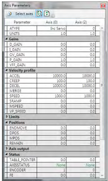
The Axis Parameters window enables the user to monitor and change the motion parameters for any axis on the controller. The display is made up of collapsible groups of parameters. This is done to make locating a parameter in the display easer and also allows the hiding of whole groups of parameters so that only parameters of interest are shown. It is also possible to individually show or hide individual parameters.
Parameters which can be edited have the normal edit box background and those which are read-only have a greyed-out background.
VIEWS
There are two main views; filtered view which shows selected parameters (see above) and all parameter view which allows the selection of individual parameters for the filtered view. Normally the filtered view is used. The view is selected by using the “all parameters” toggle button on the left of the window’s toolbar.
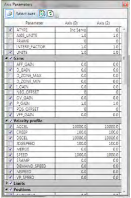
The “all parameters” view has a check box next to each parameter and group. If the box is checked then the corresponding parameter or group is displayed in the filtered view, otherwise it is hidden.
EDITING A PARAMETER
To enter a new value foe a parameter:
1. select its cell in the grid
2. type a new value
To edit a parameter:
1. double click on its cell in the grid
Digital I/O Viewer
The digital I/O viewer is used to show the states of the digital inputs and outputs of the controller (both local and remote).
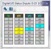
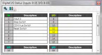
The display divides the I/O address space up into blocks of 8 lines. Usually all the lines in a block are the same type. The types available and their associated colours are shown in the table below:
Type Colour
Input Green
Output Orange
Input/Output Yellow
Virtual Input/Output Cyan
It is possible to change which banks are displayed by clicking on the “Configuration” button  which then displays the configuration dialog.
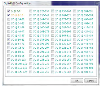
Using this dialog the user can select which banks of I/O lines to display.
Each i/0 line can be given a description. The description can be shown or hidden by clicking on the “Show/ Hide Descriptions” button or
or .
.
Analogue I/O Viewer
The analogue input viewer is used to show the values measured on the analogue inputs of the controller (both local and remote).
The tool normally displays inputs selected by the user. This defaults to showing all inputs until the user has selected which inputs to show. The value shown for each input is the raw value decoded by the hardware.
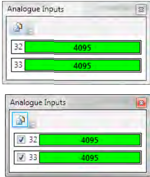
Clicking on the “Show All Inputs” button  in the toolbar toggles the display between the normal (filtered) display and the “All Inputs” display.
In “All Inputs” display mode there is a check box for each input to determine which inputs are displayed in normal mode. When in normal mode only the inputs which are checked will be displayed.
Table Viewer
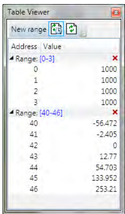
The Table Viewer tool allows the user to view and edit ranges of TABLE memory.
VIEWING A RANGE
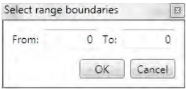
To add a range of TABLE values to the display click on the “New Range” button in the toolbar. This will bring up the “Select Range” dialog to allow the user to specify the range required.
After a range has been added to the viewer it can be edited by clicking on the corresponding range display in the tree (blue numbers), collapsed or expanded by clicking on the corresponding arrow in the tree, or deleted by on the corresponding red cross in the tree.
EDITING A VALUE
A value can be overwritten by clicking on it and entering a new value. A value can be edited by double clicking on it. In both of these cases the value is written to the controller when the “Enter” key is pressed. Pressing the “Esc” key will abort the edit. Changes can be made whilst programs are running.
REFRESHING THE VALUES DISPLAYED
The displayed valued can be updated automatically using periodic polling of the controller or manually when the user clicks on the refresh button  . Automatic refresh is controlled by the “Periodic update” button.
Clicking on the periodic update button changes its state from “Polling”  to “Not Polling”
 . The update rate can be changes on the “General” tab of the main application options dialog.
VR Viewer
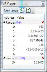
The VR Viewer tool allows the user to view and edit ranges of VR values.
VIEWING A RANGE
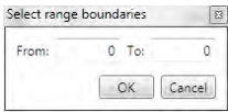
To add a range of VRs to the display click on the “New Range” button in the toolbar. This will bring up the “Select Range” dialog to allow the user to specify the range required.
After a range has been added to the viewer it can be edited by clicking on the corresponding range display in the tree (blue numbers), collapsed or expanded by clicking on the corresponding arrow in the tree, or deleted by on the corresponding red cross in the tree.
EDITING A VALUE
A value can be overwritten by clicking on it and entering a new value. A value can be edited by double clicking on it. In both of these cases the value is written to the controller when the “Enter” key is pressed. Pressing the “Esc” key will abort the edit. Changes can be made whilst programs are running.
REFRESHING THE VALUES DISPLAYED
The displayed valued can be updated automatically using periodic polling of the controller or manually when the user clicks on the refresh button . Automatic refresh is controlled by the “Periodic update” button.
Clicking on the periodic update button changes its state from “Polling” to “Not Polling”. The update rate can be changes on the “General” tab of the main application options dialog.
Watch Variables
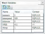
The “Watch Variables” tool allows the user to look at the values of program internal variables and global variables while a program is running or stepping.
ADDING VARIABLES
The methods of adding variables to be watched is covered in the “Program Editor” section under “Watching Variables”.
VARIABLE INFORMATION
The entry for each variable contains the name of the variable, its present value (blank if not yet read) and its context. The context is either “VR” denoting a global VR variable or the program name and the process on which it is running.
UPDATING
The displayed values can be automatically updated periodically. Periodic updating enabled or disabled by clicking on the “Toggle Periodic Updating” button ( when enabled,
  when disabled).
Clicking on the refresh button  will cause the values to be updated regardless of the state of periodic updating.
CHANGING VALUES
Values can be edited by double clicking on the value in the grid and pressing the “Return” key. The act of pressing the “Return” key sends the value to the controller.
Options Dialogue
The options dialog has several pages of options for various tools in Motion Perfect. The page displayed is controlled by a tree control on the left of the dialog.
The following can be selected from the tree:
• General
• Program editor
• Language
• Project synchronization
• Diagnostics
• Axis Parameters Tool
• Plug-ins
Plugin options pages. These depend on which plugins are installed but may include:
• Oscilloscope
• IEC61131-3 Editing
• HMI Editing
Options – Axis Parameters Tool
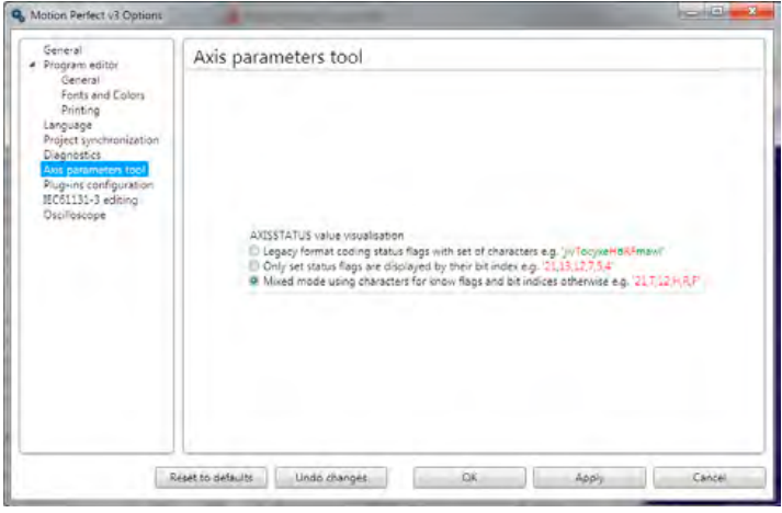
AXISSTATUS VISUALIZATION
This controls how the AXISSTATUS parameter is displayed in the parameter grid. The parameter can be displayed in one of three ways:
• Legacy Format – This is the same as Motion Perfect 2 and shows each known status bit as an alphabetic character, lower case green for clear, upper case red for set.
• Numeric Set Flag Format – This shows all known set status bits as their bit number. No clear bits are shown.
• Mixed Set Flag Format – This shows all known set bits as an alphabetic character and all unknown set bits as their bit number. No clear bits are shown.
Unknown flag bits can occur when new features are added to a controller
Options - Diagnostics
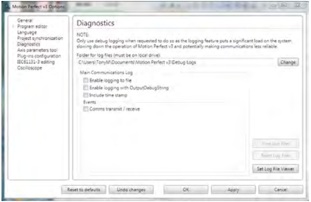
This page give options for diagnostics functions used to aid Trio Motion Technology in finding and rectifying faults in Motion Perfect.
Diagnostic functions should only be enabled on instruction from Trio Motion Technology as they reduce the application’s performance and can lead to the application being less reliable.
Options – General
Options are available for the following:
TOKEN TABLE CACHING
When “Cache TOKENTABLE response locally” is checked, token table data for each controller type and system version used is stored on the PC. The token data is used by Motion Perfect to check that certain TrioBASIC commands are supported on the controller. If the token table data is not cached locally then it has to be read from the controller every time Motion Perfect connects in Tool Mode or Sync Mode.
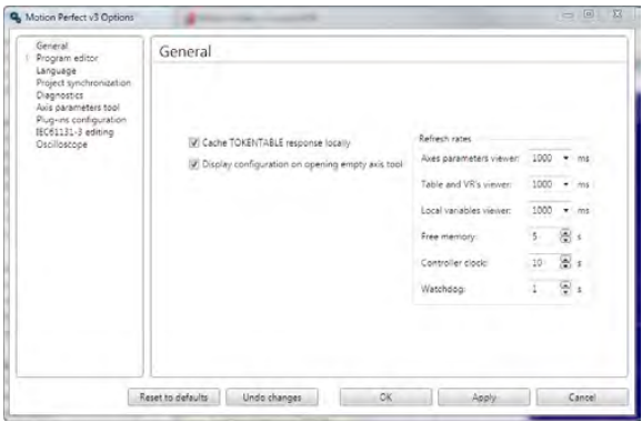
Token table caching should be left enabled in order to speed up the connection process. The only time when it may need to be disabled is if special versions of controller system software (provided by Trio Motion Technology) are used on a controller.
DISPLAY CONFIGURATION ON OPENING EMPTY AXIS TOOL
When checked, opening a tool which displays axis date will open an axis selection dialog if no axes have been previously selected.
REFRESH RATES
This allows the user to select the update rates used by various tools and monitoring processes. If a tool is set to update too frequently it may interfere with the operation of other tools due to the limited bandwidth of the communications link,
Options – IEC 61131 Editing
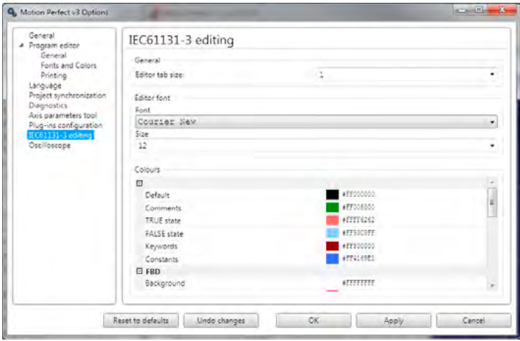
This allows the user to select options for the IEC61131-3 program editors. Some sections are common to all IEC61131-3 editors, others specific to the IEC61131-3 program type.
Options - Language
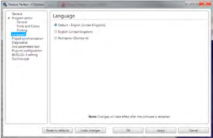
This allows the user to choose which of the available languages will be used by Motion Perfect to display text in the user interface. English (UK) will always be available, the availability of other languages may vary with application version.
Options – Oscilloscope
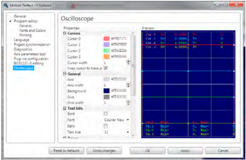
This allows the user to change the display parameters used by the oscilloscope including:
• Background colour
• Grid colour and line thickness
• Trace colour, line thickness and data point size
• Cursor colour and line thickness
• Font used to display text
• Scale matching for X/Y plots
• Data set buffering for X/Y plots
Options – Plug-ins
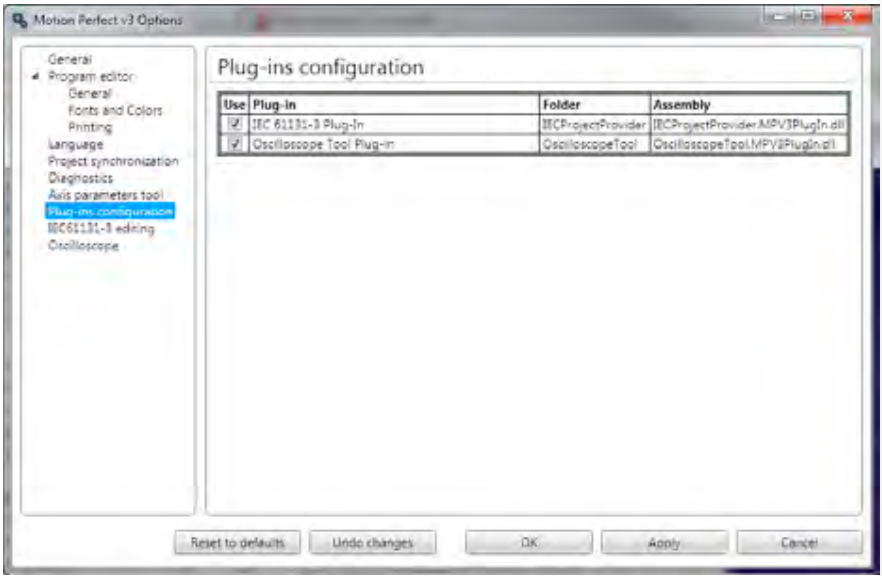
This page lists all the installed plug-ins and allows the user to enable or disable each one by means of a check box.
Options – Program Editor
The program editor options are controlled using three different pages:
PROGRAM EDITOR – GENERAL PAGE
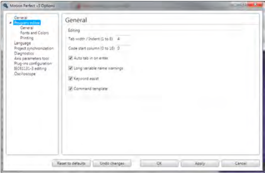
This page specifies the options for automatic assistance whilst editing:
Tab width – the number of spaces to use for tabs
Code start column – the start column for line of TrioBASIC code when auto-formatting (label definition lines always start in column 0).
Auto-tab on enter – When checked enters spaces at the start of the new line to match the start column of the current line.
Long variable names warning – if checked the user is warned if a variable name is longer than the unique name size supported by the controller.
Variable names can be longer than the unique name size but the controller only checks the first
“unique name size” characters for uniqueness.
Keyword assist – If checked the user is presented with a list of possible keywords as a keyword (or variable name) is being typed in.
Command template – If checked, when the user types a command which has parameters in brackets, a template is displayed to remind the user of the parameters.
PROGRAM EDITOR – FONTS PAGE
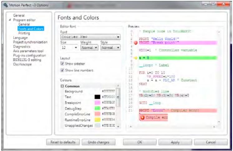
This page allows the user to specify which font is to be used in the editor (including its weight and size). It also specifies the colours used for editing and debugging including syntax highlighting of TrioBASIC programs.
PROGRAM EDITOR – PRINTING PAGE
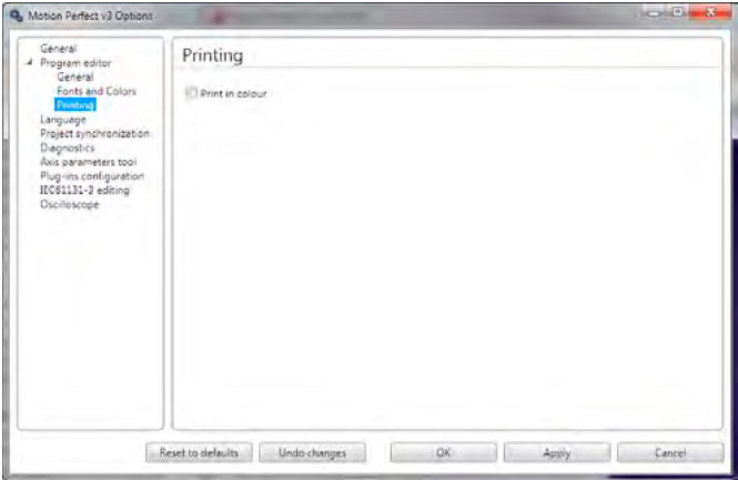
This page controls how program listings are printed.
PRINT IN COLOUR
If this is checked then the printout is coloured using the same syntax highlighting colouring scheme as the editor screen display. Otherwise the printout is done in monochrome.
Options – Project Synchronization
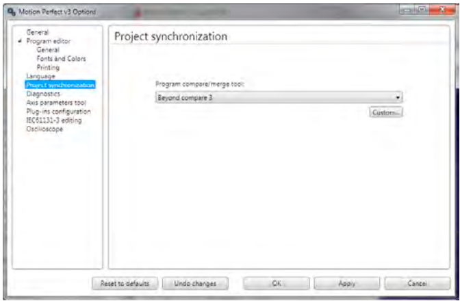
This allows the user to select a program to use to compare the difference between the copy a program on the controller and the one in the project. I allows the user to configure any program which can compare text files. A list of common text file comparison programs is given in the drop down list.
Clicking on the “Custom” button will display the “Program Compare custom tool” dialog which allows the user to specify any suitable program already installed on the PC and which command line arguments are to be used.
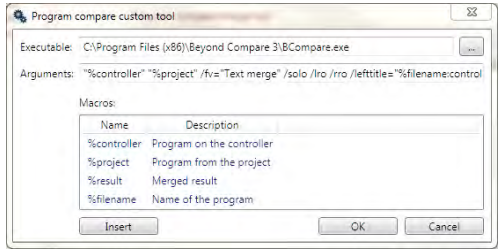
If you do not have a suitable text file compare program installed on your computer, WinMerge can be downloaded free of charge from winmerge.org
Diagnostics
Motion Perfect has some built-in diagnostics which are designed to provide useful information in diagnosing some communications problems and possibly problems with Motion Perfect functionality. Diagnostic functions should not be used unless requested to do so by Trio Motion Technology, as enabling diagnostics increases the load on the application and can, in some cases, lead to unreliability.
See “Options – Diagnostics”
Jog Axes
The Jog Axes tool allows the user to move the axes on the Motion Coordinator.
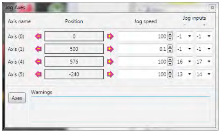
This tool takes advantage of the bi-directional I/O channels on the Motion Coordinator to set the jog inputs. The forward, reverse and fast jog inputs are identified by writing to the corresponding axis parameters and are expected to be connected to NC switches. This means that when the input is on (+24V applied) then the corresponding jog function is DISABLED and when the input is off (0V) then the jog function is ENABLED.
The jog functions implemented here disable the fast jog function, which means that the speed at which the jog will be performed is set by the JOGSPEED axis parameter. What is more this window limits the jog speed to the range 0..demand_speed, where the demand_speed is given by the SPEED axis parameter.
Before allowing a jog to be initiated, the jog window checks that all the data set in the jog window and on the Motion Coordinator is valid for a jog to be performed.
 JOG REVERSE
This button will initiate a reverse jog. In order to do this, the following check sequence is performed:
• If this is a SERVO or RESOLVER axis and the servo is off then set the warning message
• If this axis has a daughter board and the WatchDog is off then set the warning message
• If the jog speed is 0 the set the warning message
• If the acceleration rate on this axis is 0 then set the warning message
• If the deceleration rate on this axis is 0 then set the warning message
• If the reverse jog input is out of range then set the warning message
• If there is already a move being performed on this axis that is not a jog move then set the warning message
If there were no warnings set, then the message “Reverse jog set on axis?” is set in the warnings window, the FAST _ JOG input is invalidated for this axis, the CREEP is set to the value given in the jog speed control and finally the JOG _ REV output is turned off, thus enabling the reverse jog function.
 JOG FORWARD
This button will initiate a forward jog. In order to do this, a check sequence identical to that used for Jog Reverse is performed.
JOG SPEED
This is the speed at which the jog will be performed. This window limits this value to the range from zero to the demand speed for this axis, where the demand speed is given by the SPEED axis parameter. This value can be changed by writing directly to this control or using the jog speed control. The scroll bar changes the jog speed up or down in increments of 1 unit per second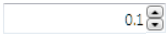
JOG INPUTS
These are the inputs which will be associated with the forward / reverse jog functions.
They must be in the range 8 to the total number of inputs in the system as the input
channels 0 to 7 are not bi-directional and so the state of the input cannot be set by the
corresponding output. Both real and virtual I/O lines can be used for jogging. The value -1
is shown when no input has been allocated for jogging.
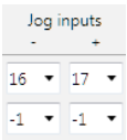
The jog function depends on the state of the jog inputs as follows: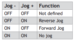
WARNINGS
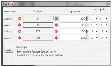
This shows the status of the last jog request. For example, the screen below shows axis 0 with IO channel 7 selected. This is an Input-only channel and therefore cannot be used in the jog screen.
AXES
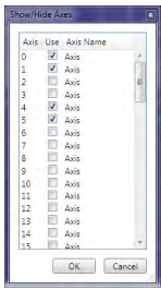
This displays an axis selector box which enables the user to select the axis to include in the jog axes display.
By default, the physical axes fitted to the controller will be displayed.
Oscilloscope
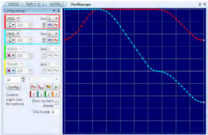
The software oscilloscope can be used to trace axis and motion parameters, aiding program development and machine commissioning.
There are four channels, each capable of recording at up to 1000 samples/sec, with manual cycling or program linked triggering.
The controller records the data at the selected frequency, and then uploads the information to the
oscilloscope to be displayed. If a larger time base value is used, the data is retrieved in sections, and the trace is seen to be plotted in sections across the display. Exactly when the controller starts to record the required data depends upon whether it is in manual or program trigger mode. In program mode, it starts to record data when it encounters a TRIGGER instruction in a program running on the controller. However, in manual mode it starts recording data immediately.
CONTROLS
There are four groups of controls, one for each of the oscilloscope’s four channels, a group of horizontal function controls and a group to control up to four cursors.
OSCILLOSCOPE CHANNEL CONTROLS
The controls for each of the four channels are grouped together and are surrounded by a coloured rectangle if the channel is ON, or a coloured bar to the left of the group if the channel is OFF. The colour is the same as the trace for that channel.
The group contains controls for channel operating mode, parameter selection and scaling.
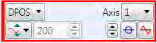
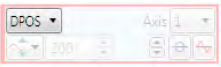
PARAMETER
The parameters which the oscilloscope can record and display are selected using the pull-down list box in the upper left hand corner of each channel control block. Depending upon the parameter chosen, the next label switches between `axis’ or `ch’ (channel). This leads to the second pulldown list box which enables the user to select the required axis for a motion parameter, or channel for a digital input/output or analogue input parameter. It is also possible to plot the points held in the controller table directly, by selecting the `TABLE’ parameter, followed by the number of a channel whose first/last points have been configured using the advanced options dialog. If the channel is not required then `NONE’ should be selected in the parameter list box.
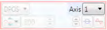
AXIS / CHANNEL NUMBER
A pull-down list box which enables the user to select the required axis for a motion parameter, or channel for a digital input/output or analogue input parameter. The list box label
switches between being blank if the oscilloscope channel is not in use, `axis’ if an axis parameter has been selected, or `ch’ if a channel parameter has been selected.
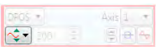
OPERATING MODE
The channel operating mode controls how the trace is displayed and scaled

VERTICAL SCALING
In automatic mode the oscilloscope calculates the most appropriate scale when it has finished recording, prior to displaying the trace. The value shown is the value calculated by
the oscilloscope.
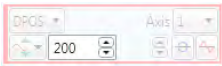
In manual mode the user selects the scale per grid division. The vertical scale is changed by pressing the up/down scale buttons on the left side of the current scale text box.
CHANNEL TRACE VERTICAL OFFSET
There are three controls which control the vertical offset of the trace:
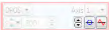
 The Vertical Offset buttons are used to move a trace vertically on the display. This control is of particular use when two or more traces are identical, in which case they overlay each other and only the uppermost trace will be seen on the display.
 The Zero Offset button clears the vertical offset.
 The auto-zero button, when active (in the down position), applies automatic vertical offset to the channel. The vertical offset and Zero Offset buttons are disabled (greyed out). This is equivalent toAC coupling on a conventional oscilloscope.
When not active the vertical offset manually set using the Vertical Offset buttons is applied. The vertical offset and Zero Offset buttons are enabled.
OSCILLOSCOPE HORIZONTAL CONTROLS
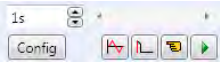
The oscilloscope horizontal controls appear towards the bottom of the oscilloscope control panel. From here you can control such aspect as the timebase, triggering modes and memory used for the captured data.
TIMEBASE
The required time base is selected using the up/down scale buttons on the left side of the current time base scale text box. The value selected is the time per grid division on the display.
If the time base is greater than a predefined value, then the data is retrieved from the controller in sections (as opposed to retrieving a compete trace of data at one time.) These sections of data are plotted on the display as they are received, and the last point plotted is seen as a white spot.
After the oscilloscope has finished running and a trace has been displayed, the time base scale may be changed to view the trace with respect to different horizontal time scales. If the time base scale is reduced, a section of the trace can be viewed in greater detail, with access provided to the complete trace by moving the horizontal scrollbar.
HORIZONTAL SCROLLBAR
Once the oscilloscope has finished running and displayed the trace of the recorded data, if the time base is changed to a faster value, only part of the trace is displayed. The remainder can be viewed by moving the thumb box on the horizontal scrollbar.
Additionally, if the oscilloscope is configured to record both motion parameters and plot table data, then the number of points plotted across the display can be determined by the motion parameter. If there are additional table points not visible, these can be brought into view by scrolling the table trace using the horizontal scrollbar. The motion parameter trace does not move.
HORIZONTAL DISPLAY MODE
Button up = x/t (timebase) mode.
This is the normal operation mode for an oscilloscope where each set of gathered data is plotted against time.
Button down = x/y mode.
Channels are grouped in pairs and the values form one channel are plotted against the values of the other one in the pair.
ONE SHOT / REPEAT TRIGGER MODE
Button up = One Shot Trigger Mode.
In one-shot mode, the oscilloscope runs until it has been triggered and one set of data recorded by the controller, retrieved and displayed.
Button down = Continuous (Auto-repeat) Trigger Mode.
In continuous mode the oscilloscope continues running and retrieving data from the controller each time it is re-triggered and new data is recorded. The oscilloscope continues to run until the trigger button is pressed for a second time.
MANUAL/PROGRAM TRIGGER MODE
The manual/program trigger mode button toggles between these two modes. When pressed, the oscilloscope is set to trigger in the program mode, and two program listings can be seen on the button. When raised, the oscilloscope is set to the manual trigger mode, and a pointing hand can
be seen on the button.
Button up = Manual Trigger Mode:
In manual mode, the controller is triggered, and starts to record data immediately the oscilloscope trigger button is pressed.
Button down = Program Trigger Mode:
In program mode the oscilloscope starts running when the trigger button is pressed, but the controller does not start to record data until a TRIGGER instruction is executed by a program running on the controller. After the trigger instruction is executed by the program, and the controller has recorded the required data.
The required data is retrieved by the oscilloscope and displayed.
The oscilloscope stops running if in one-shot mode, or it waits for the next trigger on the controller if in continuous mode
OSCILLOSCOPE CURSORS
The cursor bars are enabled/disabled by clicking on one of the cursor buttons which shows/hides the corresponding cursor. A cursor can be moved by positioning the mouse cursor over the required bar, holding down
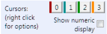
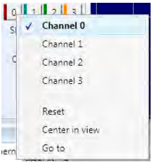
the left mouse button, and dragging the bar to the required position. Cursors are automatically allocated to the first channel currently enabled. To allocate a cursor to a different channel, right click on its button and choose the desired channel from the pop-up menu. When a cursor is active a coloured bar representing the channel to which the cursor has been allocated is displayed under the cursor’s button.
The cursor (right click) menu allows the user to assign the cursor to a channel and also contains Reset which resets the cursor position to a position close to the start of the display and Go To which scrolls the display so that the cursor is visible (only if zoomed in).
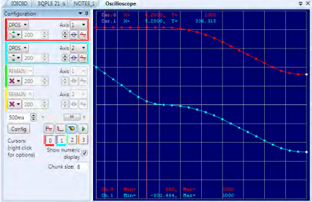
If the Show numeric display box is checked then the numeric display is enabled, this shows maximum and minimum values for all enabled traces at the bottom of the oscilloscope display and the positions of the active cursors at the top.
CAPTURE CONFIGURATION
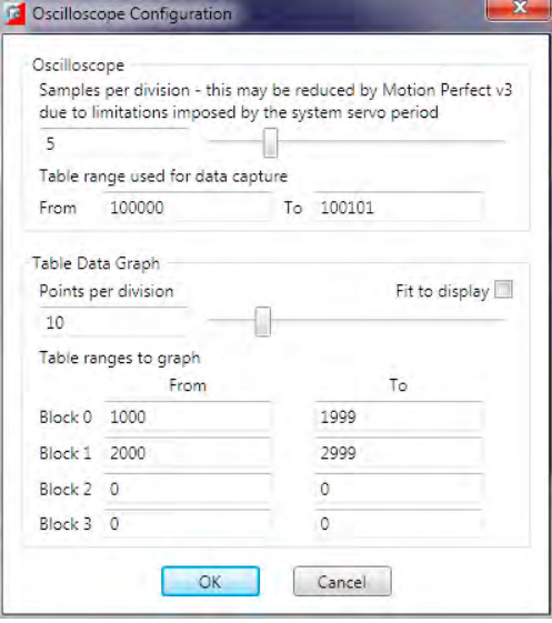
When the Config button is pressed the oscilloscope capture configuration dialog is displayed, as shown below. Click the mouse button over the various controls to reveal further information.
SAMPLES PER DIVISION
The oscilloscope defaults to recording five points per horizontal (time base) grid division. This value can be adjusted using the adjacent scrollbar.
To achieve the fastest possible sample rate it is necessary to reduce the number of samples per grid division to 1, and increase the time base scale to its fastest value (1 servo period per grid division).
It should be noted that the trace might not be plotted completely to the right hand side of the display, depending upon the time base scale and number of samples per grid division.
OSCILLOSCOPE TABLE VALUES
The controller records the required parameter data values in the controller as table data prior to uploading these values to the scope. By default, the lowest oscilloscope table value used is zero. However, if this conflicts with programs running on the controller which might also require this section of the table, then the lower table value can be reset.
The lower table value is adjusted by setting focus to this text box and typing in the new value. The upper oscilloscope table value is subsequently automatically updated (this value cannot be changed by the user), based on the number of channels in use and the number of samples per grid division. If an attempt is made to enter a lower table value which causes the upper table value to exceed the maximum permitted value on the controller, then the original value is used by the oscilloscope.
TABLE DATA GRAPH
It is possible to plot controller table values directly, in which case the table limit text boxes enable the user to enter up to four sets of first/last table indices.
PARAMETER CHECKS
If analogue inputs are being recorded, then the fastest oscilloscope resolution (sample rate) is the number of analogue channels in milliseconds ( i.e. 2 analogue inputs infers the fastest sample rate is 2msec). The resolution is calculated by dividing the time base scale value by the number of samples per grid division.
It is not possible to enter table channel values in excess of the controllers maximum TABLE size, nor to enter a lower oscilloscope table value. Increasing the samples per grid division to a value which causes the upper oscilloscope table value to exceed the controller maximum table value is also not permitted.
If the number of samples per grid division is increased, and subsequently the time base scale is set to a faster value which causes an unobtainable resolution, the oscilloscope automatically resets the number of samples per grid division.
Before the oscilloscope is triggered a sample quantization check is done to make sure that it is possible to gather the data at the sample interval requested. This may cause the number of samples per division to be adjusted so that the controller is able to gather the data at a sample period which is a whole number of servo cycles.
OPTIONS
The oscilloscope options are used to control the visual look of the oscilloscope display. Most colours and line thicknesses can be set, allowing the user to set up the oscilloscope to their own preference.
The X/Y mode only settings control the matching of the two channels used to capture X/Y data and the number of data sets buffered (and displayed) when in X/Y mode.
General Oscilloscope Information
DISPLAYING CONTROLLER TABLE POINTS
If the oscilloscope is configured for both table and motion parameters, then the number of points plotted across the display is determined by the time base (and samples per division). If the number of points to be plotted for the table parameter is greater than the number of points for the motion parameter, the additional table points are not displayed, but can be viewed by scrolling the table trace using the horizontal scrollbar.
DATA UPLOAD FROM THE CONTROLLER TO THE OSCILLOSCOPE
If the overall time base is greater than a predefined value, then the data is retrieved from the controller in blocks, hence the display can be seen to be updated in sections. The last point plotted in the current section is seen as a white spot.
If the oscilloscope is configured to record both motion parameters, and also to plot table data, then the table data is read back in one complete block, and then the motion parameters are read either continuously or in blocks (depending upon the time base).
Even if the oscilloscope is in continuous mode, the table data is not re-read, only the motion parameters are continuously read back from the controller.
ENABLING/DISABLING OF OSCILLOSCOPE CONTROLS
Whilst the oscilloscope is running all the oscilloscope controls except the trigger button are disabled. Hence, if it is necessary to change the time base or vertical scale, the oscilloscope must be halted and re-started.
DISPLAY ACCURACY
The controller records the parameter values at the required sample rate in the table, and then passes the information to the oscilloscope. Hence the trace displayed is accurate with respect to the selected time base. However, there is a delay between when the data is recorded by the controller and when it is displayed on the oscilloscope due to the time taken to upload the data via the communications link.
Intelligent Drives
Intelligent drive are drives which contain built-in control loops and are controlled via a digital interface, often over a data bus. Motion Perfect supports the configuration but means of add-ins. The following add-ins are currently available:
Add-in Drives Supported
Controller Project Dialogue
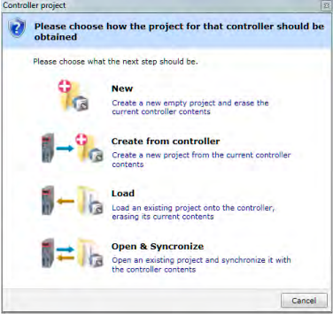
The “Controller Project Dialog” is displayed when the user first attempts a Sync Mode connection to a controller. The options available are explained on the dialog.
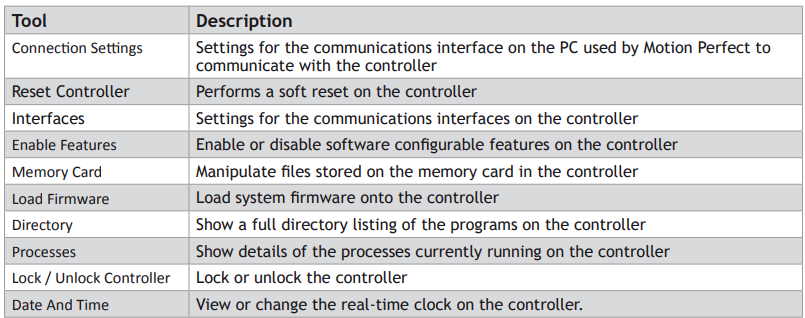
Controller Tools
Motion Perfect 3 has several tools which are used to configure the controller and interact with it. Most of these tools are available from the “Controller” section of the Main Menu.
Feature Configuration
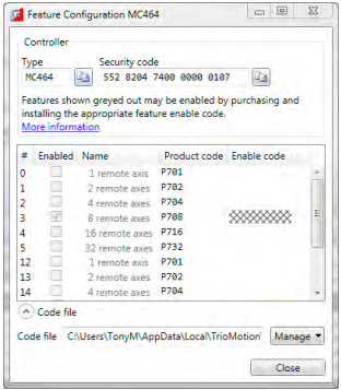
Some Motion Coordinators have features which can be enabled by the user. The features are enabled using the “Feature Configuration” tool.
FEATURE CODES
The features are made available by purchasing feature enable codes from Trio Motion Technology Ltd, each feature having a unique code, the codes also being different for every controller. Feature codes are stored on the computer in a special file on the computer which holds all feature codes entered. This file (default “FeatureCodes.tfc”) is normally located in the “TrioMotion \ MotionPerfectV3” sub directory of the current user’s local application data directory. The file used can be changed to another in a different location by clicking on “Manage” button and selecting “ Change from the drop-down list. It is also possible to import values from another Feature Code file by selecting “Import” from the same drop-down list.
To manually enter a new code select the appropriate “Enable” Code” cell in the feature grid and enter the code, being careful to get the case of the characters correct. If the code is entered correctly then the “Enabled” check box for the feature should become enabled and allow the user to enable and disable the feature.
When purchasing feature codes you will need to supply the Security code for your controller to ensure that you get the correct codes.
Feature codes are based on three factors: the feature number, an internal device code held in the controller, and the serial number of the controller. Each code is unique, so it is vital that the correct security code and feature number (or product code) are used when ordering a feature code.
Load System Firmware
Motion Coordinators feature a flash EPROM for storage of both user programs and the system firmware. Using Motion Perfect it is possible to upgrade the system firmware to a newer version using a system file supplied by Trio.
We do not advise that you load a new version of the system firmware unless you are specifically advised to do so by your distributor or by Trio.
The process of loading new system firmware will erase all programs stored on the controller. So make sure that they are backed up (in a project on the PC) before starting.
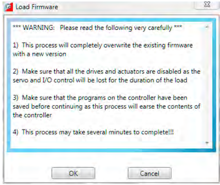
When you select the ‘Load Firmware’ option from the controller menu, you will first be presented with a warning dialog to ensure you have saved your project and are sure you wish to continue.
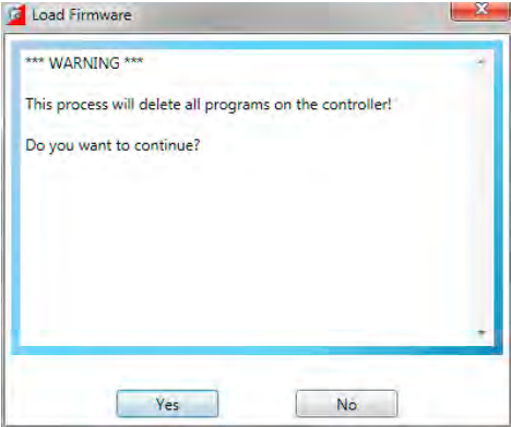
if you click on OK you will then be warned that the operation will delete all programs on the controller. This must be done because the programs are stored on the controller in a tokenized form and loading new system code may change the token list, consequently changing the commands in the programs.
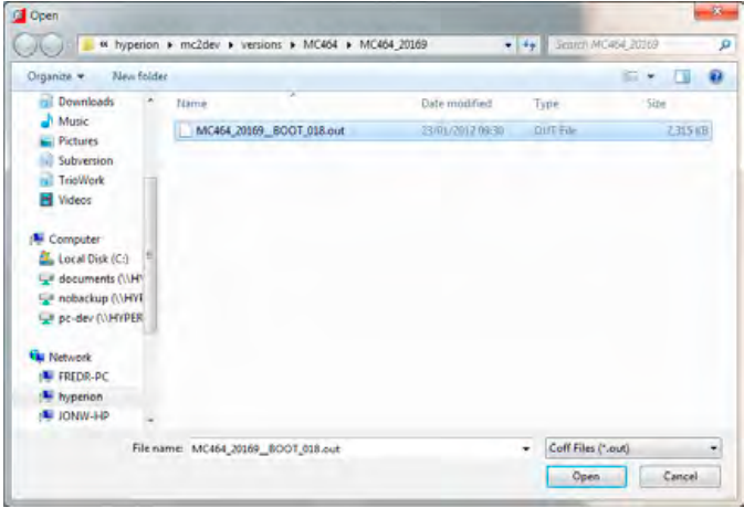
When you click on Yes you will be presented with the standard Windows file selector to choose the file you wish to load.
Each Motion Coordinator controller has its own system file, identified by the first characters of the file name.
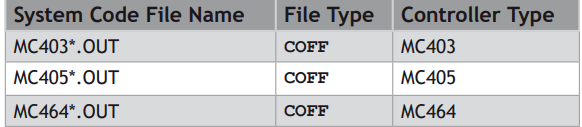
You must ensure that you load only software designed for your specific controller, other versions will not work and will probably make the controller unusable.
When you have chosen the appropriate file you will be prompted once again to check that you wish to continue. Click on Yes to start the download process.
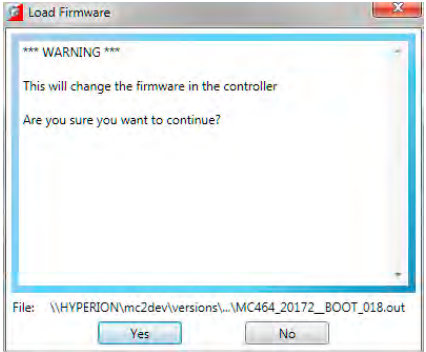
Downloading may take several minutes, depending on the speed of your PC, the controller and the communications link being used. During the download, you should see the names of each section displayed in the Output Window as they are loaded.
When the download is complete, a checksum check is performed to ensure that the download process was successful. If it passes the check you will be presented with a confirmation screen and asked if you wish to store the firmware into EPROM.
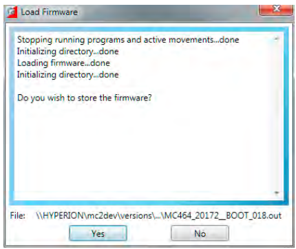
When you click on Yes a further warning dialog is displayed.
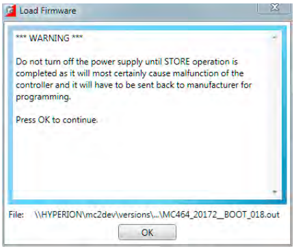
It will take a short time to fix the project into the EPROM and reconnect to the controller. You can then click on Yes and continue using Motion Perfect in the normal way.
It is advisable to check the controller configuration to confirm the new firmware version.
Lock / Unlock Controller
Locking the controller will prevent any unauthorised user from viewing or modifying the programs in memory, and also prevent Motion Perfect from connecting in Sync mode.
LOCKING
To Lock the currently connected controller, select “Controller / Lock Controller” from the main menu.
In the “Controller Lock” dialog, enter a numeric code (up to 7 digits) as a lock code. This value will be encoded by the system and used to lock the directory structure. The lock code is held in encrypted form in the flash memory of the controller.
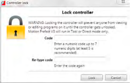
If you forget the lock code there is no way to unlock the controller. You will need to return it to Trio or a distributor to have the lock removed.
When the controller is locked the controller icon in the “Controller Tree” will have a lock symbol overlaid on it,

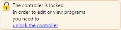
a message will be shown at the bottom of the controller tree,
and the controller name in the “Status Bar” will have a lock symbol next to it.
UNLOCKING
To Unlock the currently connected controller, select “Controller / Unlock Controller” from the main menu (only available when the controller is locked).
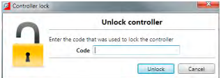
Enter the lock code with which the controller was previously locked. After the lock code has been accepted full access to the contents of the controller will be restored.
Memory Card Manager
The “Memory Card Manager” allows the user to manage the contents of the memory card in the controller. It is started by selecting “Controller / Memory Card” from the Main Menu.
If there is no memory card present a warning dialog is displayed.
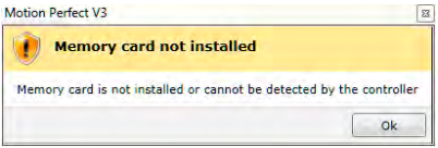
If a memory card is present the Memory Card Manager dialog is displayed.
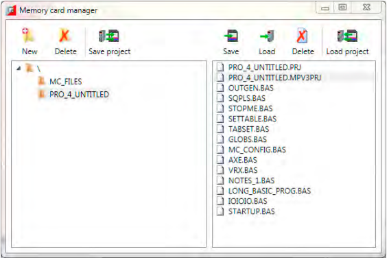
The panel on the left of the dialog shows the directory structure on the memory card and the panel on the right shows the files (not directories) in the currently selected directory.
The following operations are available:
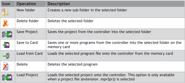
Directory Viewer
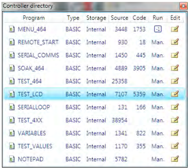
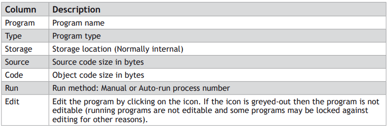
The Directory Viewer shows a more detailed directory view to that available in the “Controller Tree”. The information in the grid is as follows:
Process Viewer
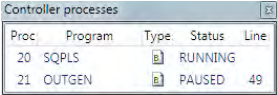
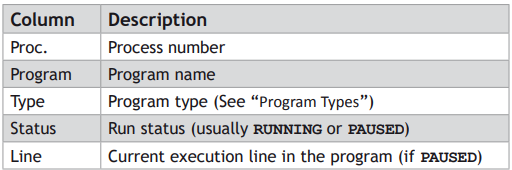
The Process Viewer shows information about all currently running user processes on the controller. The information in the grid is as follows:
Date And Time Tool
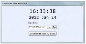
The Date and Time tool is used to monitor and set the real-time clock on the controller.
SETTING THE DATE AND TIME
The date and time can be set in two ways:
MANUAL SETTING
To set the date and time manually, click on the combo box to display a date and time selector dialog.
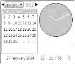
Select the date and time in the dialog then click outside it. The date and time selector dialog will close. Then click on the Set button in the Date and Time tool to update the controller.
AUTOMATIC SETTING FROM THE LOCAL PC CLOCK
To set the date and time on the controller to same time as the local PC clock, click on the “Synchronize with PC Clock” button.
STARTUP Program
The STARTUP program is an automatically generated program designed to be run at system start to initialize the system. The STARTUP program is a standard TrioBASIC program which needs to be run as a user specified auto-run program (unlike the MC _ CONFIG program which always run at power-up).
The STARTUP program should not be edited manually as doing so may result in the manual additions being lost when the program is regenerated or wrong values being generated if code used by the automatic generation process is changed.
The file is divided up into sections each section being generated by a different tool. Some add-ins will generate a section in the STARTUP file for the configuration of external devices (such as intelligent drives).
Modify STARTUP Program
The STARTUP program is a user run TrioBASIC program used to initialize the system on power-up. It is commonly used to set up Axis Parameters, TABLE areas, VR Variables and Drive Parameters (when intelligent drive support is available).
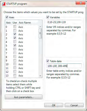
The “Modify STARTUP Program” tool allows the user to save Axis Parameters, VR Variables and TABLE data in the STARTUP file so that it can be used to initialize the system. The storing of each type of data in enabled using a check box (check to enable).
AXES
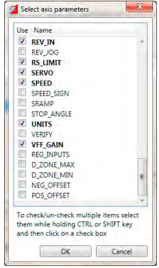
The axes whose parameters need to be stored should be selected in the axis table. After doing this click on the “Axis Parameters” button to display the “Axis Parameters Selection Dialog” which allows the user to select which parameters should be stored. The same parameters are stored for all selected axes.
VARIABLES
VR variables can be stored by specifying variable numbers and ranges of variable numbers.
e.g. 1,4,6-9,12-23 will store VR(1), VR(4), VR(6) to VR(9) and VR(12) to VR(23)
TABLE DATA
TABLE values can be stored by specifying table indices and ranges of table indices.
e.g. 1,4,6-9,12-23 will store TABLE(1), TABLE(4), TABLE (6) to TABLE (9) and TABLE (12) to TABLE (23)
MC_CONFIG Program
The MC _ CONFIG program is a special program which can contain a small subset of TrioBASIC commands. It is automatically run at power-up and is used to set some basic configuration parameters on the controller.
MC _ CONFIG, if present, is always run at power-up and does not need to be specified as an auto-run program. It is always run before user specified auto-run programs.
If a parameter is not set in MC _ CONFIG then the value in the controller’s flash EPROM memory is used.
The following system parameters can be written in the MC _ CONFIG program. No other BASIC commands or parameters are allowed. If an illegal parameter is put in the MC _ CONFIG program then it will cause a compiler error.
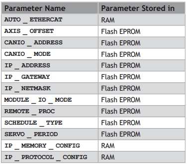
Parameter modifiers; SLOT and AXIS are allowed where appropriate.
PARAMETER DESCRIPTION
AUTO_ETHERCAT
Select the startup mode of EtherCAT. (Default: ON)
AUTO _ ETHERCAT = OFF ‘ do not start EtherCAT network on power up
AXIS_OFFSET
Set the start address of an MC464 axis module. (Default: 0)
AXIS _ OFFSET SLOT(1)=16 ‘ set start axis of module in slot 1
CANIO_ADDRESS
Set the operating mode of the built-in CAN port. (Default: 32)
CANIO _ ADDRESS=40 ‘ set the CANIO _ ADDRESS to use CANopen IO
CANIO_MODE
Determines the mode used with CANIO modules P317 (output), P318 (input) and P327 (relay).
Set to 0 to use the “up to 512” IO point mode. Set to 1 to use the mode compatible with MC2xx Motion Coordinators. (Default: 0)
CANIO _ MODE=1 ‘ set the CANIO to compatibility mode
IP_ADDRESS
Set the network IP address of the main Ethernet port. (Default: 192.168.0.250)
IP _ ADDRESS = 192.168.0.110
IP_GATEWAY
Set the default gateway of the main Ethernet port. (Default: 192.168.0.255)
IP _ GATEWAY = 192.168.0.103
IP_NETMASK
Set the subnet mask of the main Ethernet port. (Default: 255.255.255.0)
IP _ NETMASK = 255.255.240.0
MODULE_IO_MODE
Define the operation and position of the axis module digital IO. (Default: 1)
MODULE _ IO _ MODE = 2 ‘ set so that module IO is after CAN IO
REMOTE_PROC
For use in systems with the TrioPC ActiveX. When the programmer needs to allocate the ActiveX synchronous connection to use a certain process number, set this value. (Default: -1)
REMOTE _ PROC = 10 ‘ set the ActiveX to use process 10
SCHEDULE_TYPE
Alters the MC464 multi-tasking scheduler. See MC4xx Technical Reference Manual. (Default: 0)
SCHEDULE _ TYPE = 0 ‘ WA() commands release their process for ‘ other programs to use.
SCHEDULE _ TYPE = 1 ‘ WA() commands use up all their process time
SERVO_PERIOD
Set the scan period of the servo loops and motion in microseconds. (Default: 1000)
SERVO _ PERIOD = 500 ‘ set to half millisecond servo period.
IP_MEMORY_CONFIG
Set the Ethernet processor memory allocation. Buffer sizes can be increased to allow better processing of Ethernet Packets on a busy network. There is a trade-off between buffer size and the number of available protocols that can be connected. The default buffers are 2 for Tx and 2 for Rx. This allows all protocols to be used.
Increasing the buffers sizes must be done according to instructions from Trio Motion Technology, otherwise an unstable configuration may result.
IP_PROTOCOL_CONFIG
Set the available protocols ON or OFF. By default all protocols are available.
This should only be used under after taking advice from Trio Motion Technology.
Backup Manager
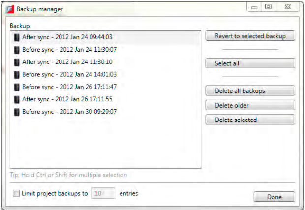
The “Backup Manager” is used to manage the backups automatically created before and after every synchronization operation.
As Motion Perfect is used the number of stored backups can become excessively large. The “Backup Manager” gives the user a way to limit these backups or to easily delete multiple backups if automatic limiting is not in use.
AUTOMATIC LIMITING
To automatically limit the number of backups stored check the “Limit Project Backups” check box and enter the number of entries you would like to keep. The backups kept are always the most recent ones. Although automatic limiting is good for saving disk space it is not good for keeping backup for any length of time.
MANUAL LIMITING
If the “Limit Project Backups” check box is not checked then no backups are deleted automatically. This means that the user should use the backup manager to remove unwanted backups in order to stop the number of stored backups growing excessively. Buttons allow the selection and deletion of individual and ranges of backups as well as the deletion of all backups.
It is possible to set the automatic limit to a high number to give an overall limit but to manage the backups manually.
REVERTING
To revert the project back to a given backup; Select the backup and click on the “Revert to Selected Backup” button.