2. Environment and installation
2.1. Environmental Conditions
A suitable environment is necessary for the robot system to function properly and safely. Be sure to install the robot system in an environment that meets the following conditions:
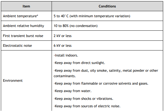
*The ambient temperature conditions are for the Robots only.
Robots are not suitable for operation in harsh environments such as painting areas, etc.
2.1.1. Special Environmental Conditions
The robot surface is generally oil resistant. Please consult your distributor if you are concerned about a certain type of oil in your application’s environment.
Rapid change in temperature and humidity might cause condensation inside the Robot.
For food handling, please consult your distributor if you feel any concern regarding the robot being suitable to handle the material.
Corrosive environments, where acid or alkaline is used, is not suitable for the robot. Robot parts are susceptible to rust in a salty environment.

2.2. Base Table
A base table for anchoring the Robot is not supplied. Please make or obtain the base table for your Robot. The shape and size of the base table differs depending on the use of the robot system. For your reference, we list some Robot table requirements here.
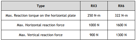
The torque and reaction force produced by the movement of the Robot are as follows:
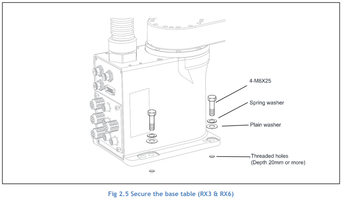
The threaded holes required for mounting the Robot base is M8 (RX3 and RX6). Use mounting bolts with specifications conforming to ISO898-1 property class: 10.9 or 12.9.
The plate for the Robot mounting face should be 20 mm thick or more and made of steel to reduce vibration. The surface roughness of the steel plate should be 25 μm or less.
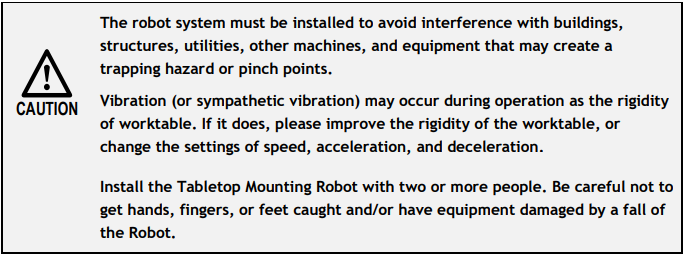
The table must be secured on the floor or wall to prevent it from moving.
The Robot must be installed horizontally.
When using a leveller to adjust the height of the base table, use a screw with M16 diameter or more.
2.3. Mounting Dimension
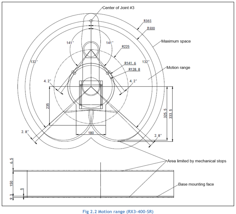
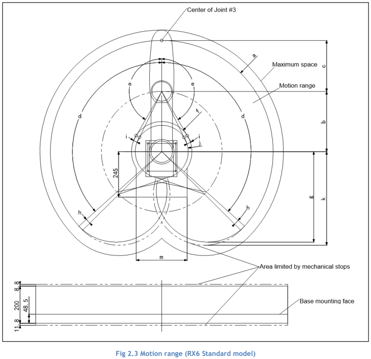
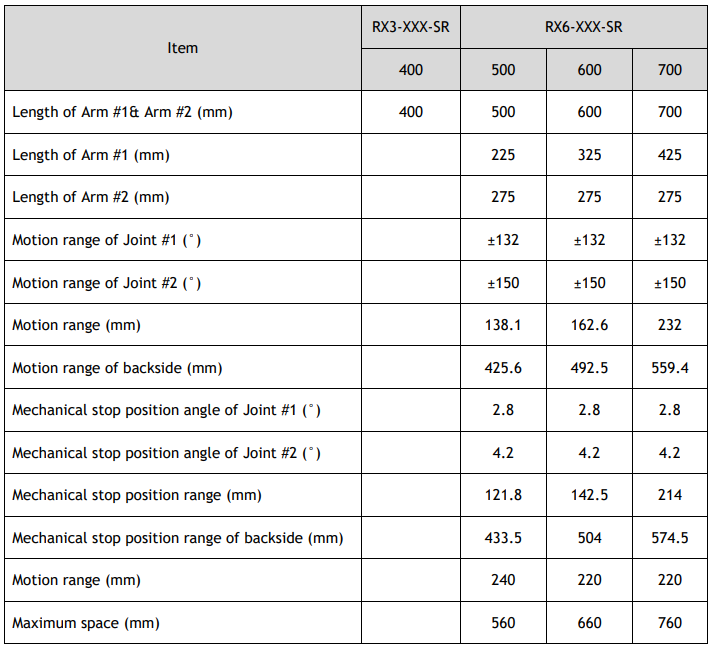
The maximum space described in section 1.2 shows that the radius of the end effector is 60 mm or less. If the radius of the end effector exceeds 60 mm, define the radius as the distance to the outer edge of maximum space.
If a camera or solenoid valve extends outside of the arm, set the maximum range including the space that they may reach.
Be sure to allow for the following extra spaces in addition to the space required for mounting the Robot, Controller, and peripheral equipment.
Space for teaching
Space for maintenance and inspection (Ensure a space open covers and plates for maintenance)
Space for cables
The minimum bend radius of the power cable is 90 mm. When installing the cable, be sure to maintain sufficient distance from obstacles. In addition, leave enough space for other cables so that they are not bent forcibly.
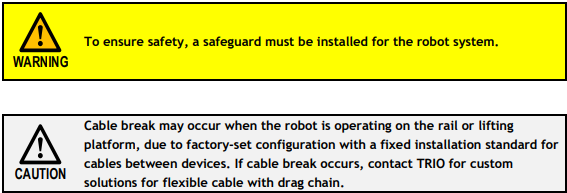
Ensure distance to the safeguard from the maximum motion range is more than 100 mm.
The maximum space described in figures shows that the motion range of the robot. Take the motion range as reference when you want to find a proper position for mounting robot. Avoid interference with robot and its motion range when mounting peripheral equipment.
2.4. Unpacking and Transportation

Using a cart or similar equipment, transport the Robot in the same manner as it was delivered.
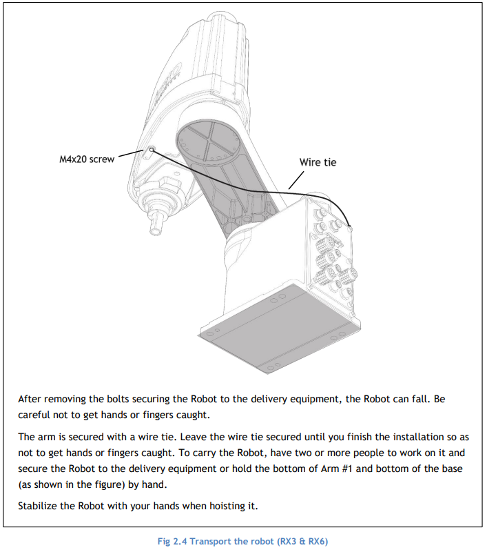
When transporting the Robot for a long distance, secure it to the delivery equipment directly so that the Robot never falls.
If necessary, pack the Robot in the same style as it was delivered.
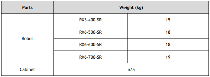
The Robot weights are as follows.

2.5. Installation Procedure
(1) Secure the base to the base table with four bolts.


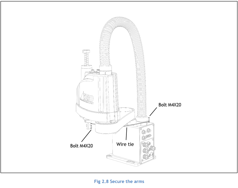
(2) Using nippers, cut off the wire tie binding the shaft and arm retaining bracket on the base.
(3) Remove the bolts securing the wire ties removed in step (2). Remove the retaining bracket on the arm.

2.6. Connecting the Cables
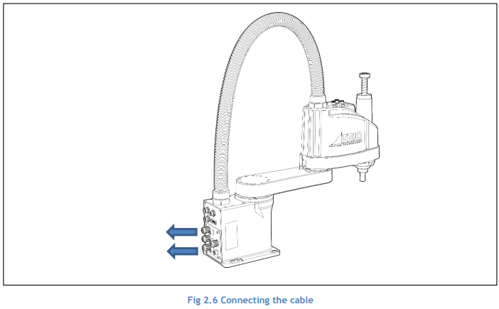
2.7. User Wires and Pneumatic Tubes

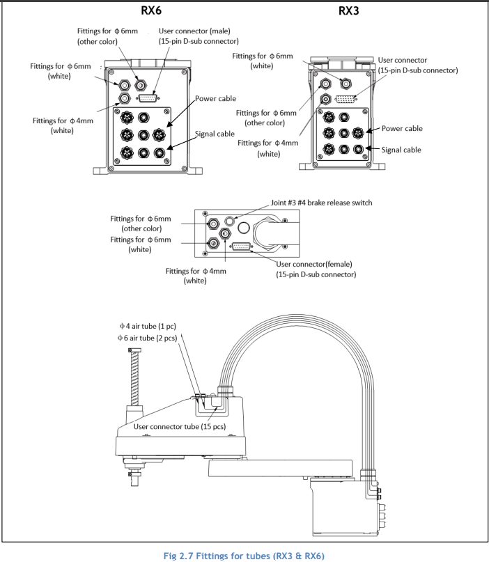
User electrical wires and pneumatic tubes are contained in the cable unit.
2.7.1.Electrical Wires


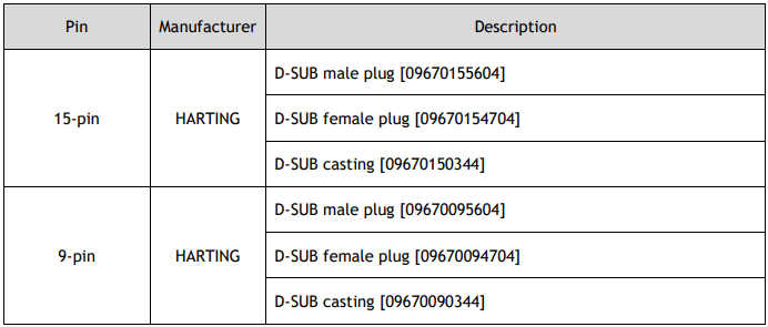
Pins with the same number, indicated on the connectors on both ends of the cables, are connected.
Connectors are standard accessories of the robot; you need not to prepare.
2.7.2.Pneumatic Tubes

Fittings for ø6 mm and ø4 mm (outer diameter) pneumatic tubes are supplied on both ends of the pneumatic tubes.
2.8. Relocation and Storage
2.8.1.Precautions for Relocation and Storage
When transporting the Robot for a long distance, secure it to the delivery equipment so that the Robot cannot fall. If necessary, pack the Robot in the same way as it was delivered.
If necessary, pack the Robot in the same way as it was delivered.
When the Robot is used for a robot system again after long-term storage, perform a test run to verify that it works properly, and then operate it thoroughly.
Transport and store the Robot in the range of -25℃ to +55℃. Humidity within 10% to 90% is recommended.
When condensation occurs on the Robot during transport or storage, turn ON the power only after the condensation dries.
Do not shock or shake the Robot during transport.

2.8.2.Relocation
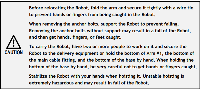
(1) Turn OFF the power on all devices and unplug the cables.
(2) Cover the arm with a sheet so that the arm will not be damaged. Tie the lower end of the shaft and arm, and the base and arm together with the wire tie. Be careful not to tie them too tight. Otherwise, the shaft may bend.
(3) Hold the bottom of Arm #1 by hand to unscrew the anchor bolts. Then, remove the Robot from the base table.