6. Calibration and battery
6.1. Introduction
Calibration associates the angle of each robot axis with the pulse count value supplied from the absolute Pulse coder connected to the corresponding axis motor. To be specific, calibration is an operation for obtaining the pulse count value, corresponding to the home position.
Factory calibration data is supplied in a separate document when purchasing the robot. These data are unique as per robot serial number.
Calibration is factory-performed. It is unnecessary to perform calibration in daily operation. However, calibration becomes necessary after:
Motor replacement
Pulse coder replacement
Reducer replacement
Cable replacement
Batteries for pulse count backup in the mechanical unit have gone dead

6.2. Finding calibration position
Calibrating is performed at the factory with no loads on the robot system, based on the robot parameters and the special tools and software. This calibration method is the most precise one. Every robot is provided with its calibration values.
The data of home position may be lost due to electrical or software problems. The stored zero position can be regarded as the reference when you perform calibration by teaching method.
The process consists of place robot in specific position by hand, allowing encoders to be at +-0.5 turn. At that position, the system can calculate the offset position if manufacture calibration values are set into the configuration software.
Procedure to calibrate the home position of J1, J2, J3 and J4 axis for RX3/RX6 Robot consists of 3 main steps:
1. Battery replacement
2. Calibration values reset
3. SCARA definition
6.2.1.Battery Replacement Steps
1. Turn power off for all axis drives.
2. Move J1, J2, J3 and J4 and align the mark on the different arms to the position as shown in the figures below.
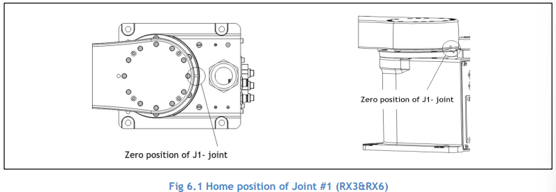

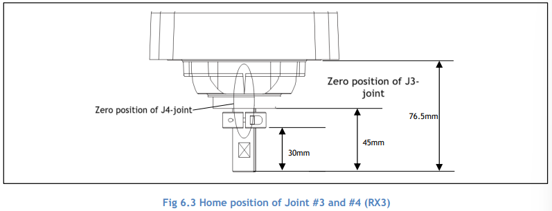
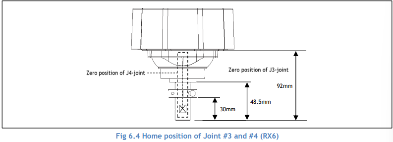
3. Remove the backplate of the battery compartment in the robot base
4. Replace batteries of J1, J2, J3 and J4 or unplug and then plug them again so absolute encoders multi turn is set to 0.
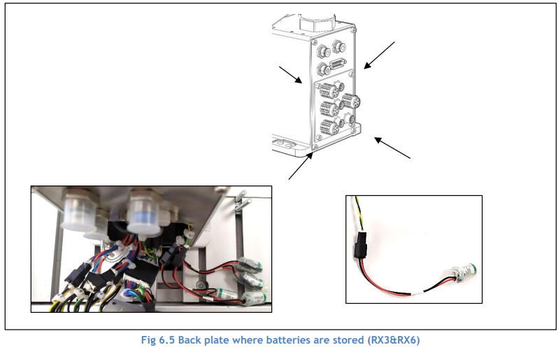

5. Put the backplate of the battery compartment back on
6. Turn the controller box unit back ON. Battery replacement steps are done.
6.2.2.Calibration Values Reset
1. Start Motion Perfect and create a new project in Motion Perfect
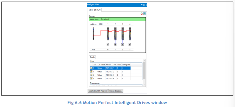
2. Make sure the Ethercat network is in operational state and all axes are all in working state (no errors). You can do this via Intelligent Drive window in Motion Perfect. Master State of the Ethercat network and each axis should look like below in Intelligent Drive. If not, perform next step to clear all errors.
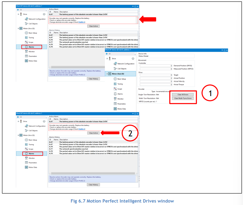
3. Go to individual axis by clicking the axis icon in Intelligent Drives window and clear any errors of each axis by ‘Clear All Errors’, ‘Clear Multi-turns Errors’, and ‘Clear Active’ in sequence as shown below.
4. Make sure the controller status is without errors as shown below

5. Notice that axis parameter ENCODER for each axis should now be around 0 due to battery power loss.

6. Restart the cabinet
7. Via Motion Perfect, make sure the Ethercat network is operational. If not, restart Ethercat network via Controller pane in Motion Perfect.

8. Axis parameter ENCODER (previously of about 0) for each axis should now reflect the proximity of the value in Calibration Data document.

6.2.3. SCARA Definition
1. Run ROBOT_DEFINITIONS file.
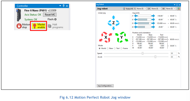
2. Switch Master Enable ON and test jog each axis of the robot.