
4. Arc Welding Control Functions
4.1Work Condition Inspection
⚫ Ensure the robot is properly positioned, anchored securely, and verify its operational status according to the ER Series Industrial Robot Operation Manual_RCS2 V1.15;
⚫ Connect the welding cables (positive and negative), to ensure that the welding table is not in electrical contact with the robot body;
⚫ Connect the communication cables between the welder and the robot (from the welder's communication box to the DB9 CANopen communication port on the robot controller), as well as the wire feeding machine cable;
⚫ Power up the robot and the welder. After the system is initiated, click on the wire feeding, gas feeding, and Wire Feed Back functions;
4.2Welding Enablement
Welding enablement serves as a mechanism to ensure the safe operation of welding equipment.
The system utilizes the welding enablement signal as a trigger to seamlessly control the initiation, progression, and conclusion of the welding process. When welding enablement is activated, users are permitted to automatically start the welder, wire feeder, gas feed unit, and other associated equipment during program execution. Conversely, when welding enablement is deactivated, the mentioned equipment will be disabled.
Welding enablement can be controlled using the teach pendant through two general methods:
⚫ Click the welding enablement button on the right side of the teach pendant interface. The welding enablement indicator on the status bar changes to  , and the button itself switches to "Welding Enablement ON".
Simultaneously, the green LED indicator for the teach pendant's welding enablement button lights up. Click the same button again to switch welding enablement OFF. This changes the indicator to , and the button to "Welding Enablement OFF". The green LED indicator on the teach pendant's welding enablement button will turn off.
⚫ Alternatively, press the welding enablement button on the teach pendant to control enablement switching.
4.3Gas Source Setup
Welding shielding gas serves as a crucial measure to ensure welding quality, and its source typically involves equipment such as gas cylinders, flow meters, pressure gauges, and ventilation pipelines. The operational state of the gas feed system is controlled using the teach pendant. To activate the gas feed system, you can either press and hold the gas feed button on the right side of the teach pendant interface or press and hold the gas feed button on the teach pendant itself. Upon activation, an audible sound from the gas valve switch confirms the opening of the gas feed unit.
4.4Wire Feed/Wire Feed Back Setup
The wire feeding system is an electromechanical device that facilitates automatic wire feeding during welding. Typically mounted on the robot body, its operation usually synchronizes with the electrode feeding machine, gas feed unit, and the robot itself. The principle is illustrated in the figure below, where the forward and reverse rotations of the wire spool within the wire feeding machine respectively initiate the wire feeding and Wire Feed Back states.
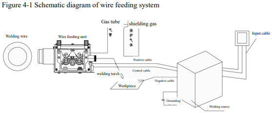
Controlling the wire feed and wire feed back of the wire feeding machine can be achieved by either pressing and holding the wire feeding button and wire feed back button on the right side of the teach pendant interface or pressing and holding the wire feeding button and wire feed back button on the teach pendant itself.
4.5Arc Re-striking Function
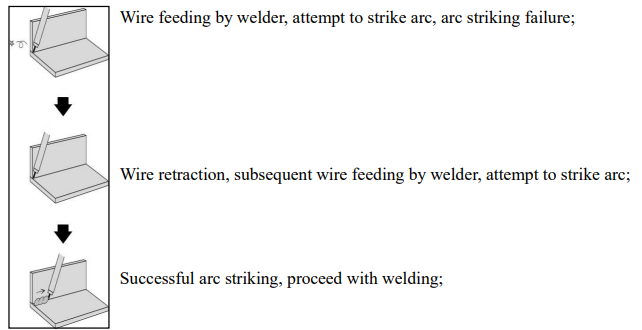
During arc striking, if the initial attempt fails, the arc re-striking function allows for a subsequent arc striking attempt. This prevents welding interruption due to initial arc striking failure.
4.5.1 Function introduction
Scenario 1: At the beginning of welding, the initial arc striking is unsuccessful.
Scenario 2: During welding, abnormal conditions result in arc discontinuity or irregular arc stopping, such as surface oxidation or oil contamination, which lead to arc striking failure or arc interruption. In this case, pressing the teach pendant's start button again will trigger the function.
Scenario 3: During welding, if the customer presses the teach pendant's stop button and the robot sends a command to stop the arc, and subsequently, if the customer presses the teach pendant's start button without any other actions.
In all the above scenarios, the arc re-striking function is activated. If arc striking fails during this attempt, the arc re-striking function will make further attempts. After a specified number of attempts, if arc striking still fails, an error will be reported; otherwise, normal welding will proceed.
4.5.2 Parameter description
⚫ Arc Re-striking Attempts: The number of attempts made to strike the arc in case of initial arc striking failure.
⚫ Arc Re-striking Current/Voltage: The current and voltage displayed on the welder panel.
4.5.3 Function process description
4.6Re-Startup Function
4.6.1 Function Introduction:
During the welding process, welding may halt due to abnormal arc interruption or customer intervention, causing the robot to come to a stop. The robot performs other operations during this time. After completing these operations, the robot re-initiates by moving back to the original welding point and then resumes the subsequent welding tasks. This allows the welding process to continue seamlessly.
4.6.2 Parameter Description:
⚫ Re-Startup Retraction Speed: Unit in mm/s, influenced by global speed settings.
⚫ Re-Startup Welding Parameters: Current parameters displayed on the welder panel.
4.6.3 Function process description:
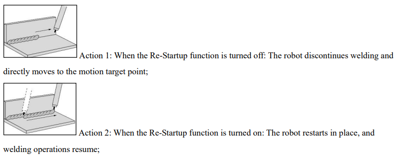

1) As shown in the figure, after completing the action, pressing the teach pendant's "Start" button initiates re-start.
The robot moves back to the original welding point at the set re-start retraction speed.
2) Afterward, the robot continues with the welding process. If manual intervention occurs during Action 1, the ongoing re-start state is cleared. Even if the robot is restarted, the Re-Startup function cannot be executed.
4.7Arc Welding Parameter Setting (Use of Arc Welding Software Package)
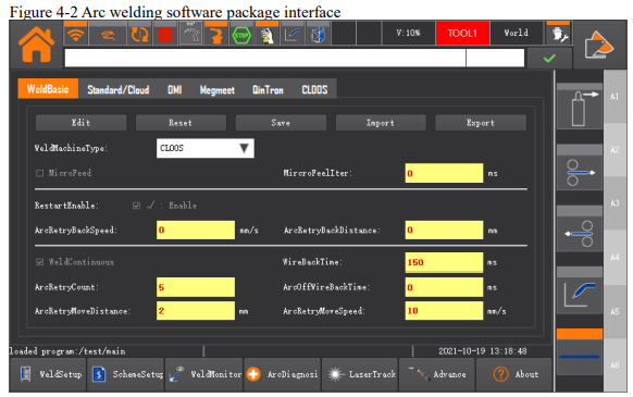
Press the "Welding Setup/Login" button or click on "Arc Welding Setup" on the Home screen to access the Arc Welding Setup interface, as shown in the figure below.
4.7.1 Welding setup
Basic Setup
In the Arc Welding Setup interface, click on the "Welding Setup" button in the bottom navigation bar to access the Welding Setup interface. The primary functions of the Welding Setup interface involve configuring welding operations and welder parameters.
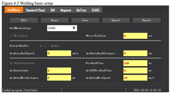
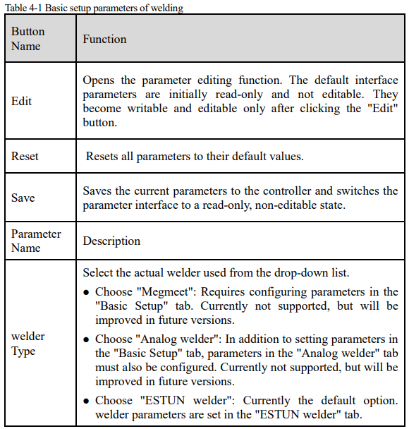
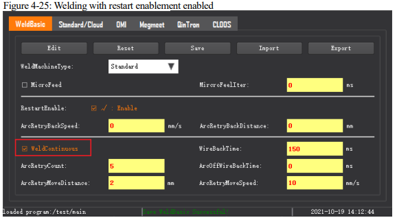
Welding Basic Setup: To set the welder Type; Welding Enablement; Re-Startup Enablement; Wire Inch Feed Enablement; Wire Inch Feed Time; Arc Re-striking Wire Feed Back Time; Arc Restriking Attempts.
In the "Welding Basic Setup" interface, users need to configure the parameters in the interface based on the actual robot operations.
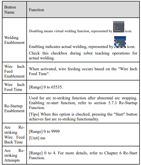
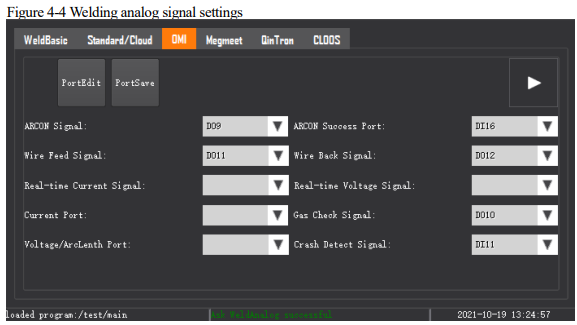
Analog Welder
⚫ To correctly configure parameters for the "Analog Welder", users need to first understand the actual wiring situation. Then, they can enter this interface and select corresponding ports for the signals listed on this interface.
As shown in the diagram. On this page, you can set signals such as Arc Striking/Stopping Signal, Successful Arc Striking/Stopping Signal, Jog Wire Feed Signal, Wire Feed Back Signal, Real-Time Current Signal, Real-Time Voltage Signal, Current Setpoint Port, Gas Detection Signal, Voltage/Arc Length Calibration Port, and Collision Detection Signal.
Function Button Explanation:
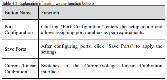
⚫ Calibration of the given current and voltage.
[Setting Note] Due to the limitations of analog output, its output range is relatively small (typically not exceeding ±10V). However, there might be a need for higher current, voltage, or arc length calibrations. To address this, a linear relationship can be established to derive the actual required values for the ports.
Clicking "Current/Voltage Linear Calibration" takes you to the interface for setting the linear relationship, as shown in the figure below.
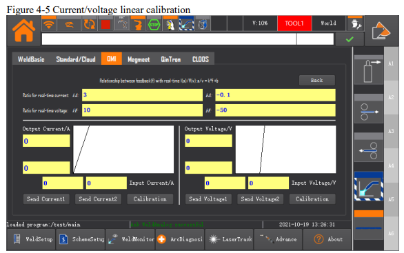
⚫ When setting up this linear relationship, input the specified value in the "Port Set" coordinate and observe the current value displayed on the welder panel. For example, if the port set value is 2V and the displayed current on the welder panel is 110A, the sequence of operations is as follows: Click "Edit 1" → Enter "2" in "Port Set" → Enter "110" in "Display Current".
⚫ Two sets of values need to be configured to establish the linear relationship. After setting, click "Calibrate" to make the configuration effective.
⚫ Try to avoid using values near the upper and lower limits to achieve the most accurate linear ratio.
⚫ When setting up the linear relationship for welding voltage/arc length calibration, consider the welding mode: Unified and Separate.
⚫ For the centralized welding mode, linear calibration of arc length correction values is required. First, switch the welding mode to the Unified; then modify the displayed value on the panel to show the arc length correction value (usually defaults to welding voltage); finally, calibrate the arc length correction following the steps for welding range calibration.
⚫ For the separate welding mode, linear calibration of the specified voltage is required. First, switch the welding mode to the Separate; then change the displayed value on the panel to show welding voltage; finally, calibrate the welding voltage following the steps for welding range calibration.
[Note] If the user wants to change the welding mode midway, linear calibration for the parameters corresponding to the other mode is required.
ESTUN Welder
If you select "ESTUN CANOPEN Communication Welder" as the "Welder Type" in the "Basic Setup" interface, you need to configure the parameters in this tab in addition to setting parameters in the "Basic Setup" tab, as shown in the diagram below.
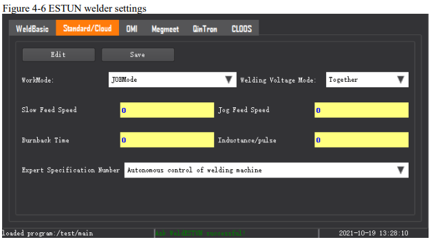
⚫ Operating Mode: Select the operating mode of the ESTUN welder from the drop-down list.
1. 1. Flat Characteristic Mode (Refer to the welder manual for details)
2. Pulse Mode (Refer to the welder manual for details)
3. JOB Mode (Refer to the welder manual for details)
4. Low Spatter Mode (Refer to the welder manual for details)
Note: The default mode is currently Flat Characteristic Mode. Refer to the welder manual for other modes.
⚫ Welder Mode: Select the welding mode of the ESTUN welder from the drop-down list.
[Note] This parameter needs to be used in conjunction with P19 on the welder panel. (Refer to the welder manual for details)
⚫ Separate: When welding, arc striking is based on "Current" and "Voltage" directly. (Refer to the welder manual for details)
⚫ Unified: When welding, arc striking is based on "Current" and "Arc Length Correction". (Refer to the welder manual for details)
Note: The default mode is currently Unified Mode.
QinTron Welder
If you select "QinTron Welder" as the "Welder Type" in the "Basic Setup" interface, you need to configure the parameters in this tab in addition to setting parameters in the "Basic Setup" tab, as shown in the figure below.
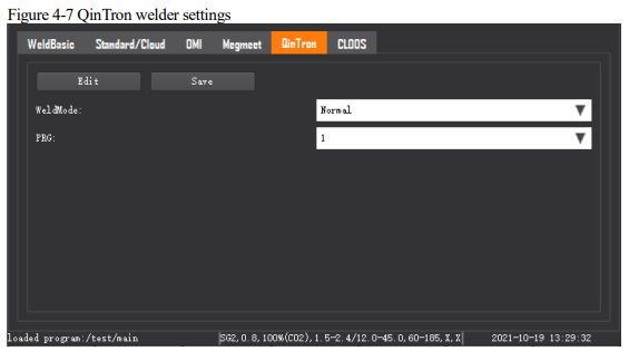
Explanation of Function Buttons:
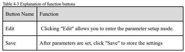
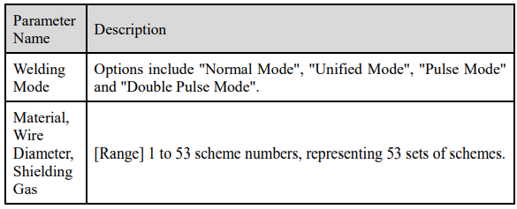
CLOOS Welder
If you select the "CLOOS" option in the "Basic Setup" interface, you need to configure the parameters on this page in addition to setting parameters on the "Basic Setup" page, as shown in the figure below.
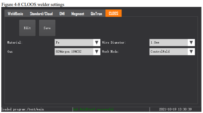
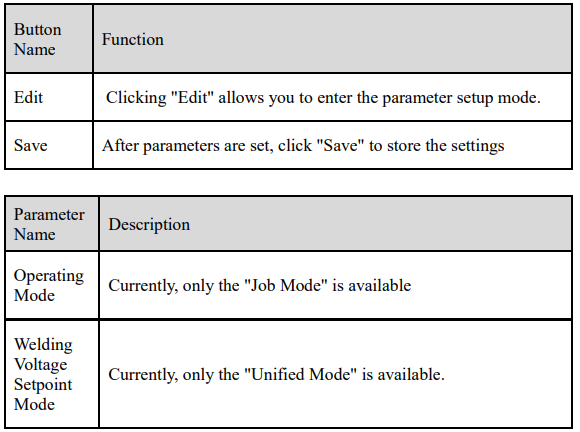
Explanation of Function Buttons:
4.7.2 Scheme configuration
Welder Specification
In the Arc Welding Setup interface, click on the "Scheme Configuration" button in the bottom navigation bar to access the Scheme Configuration interface.
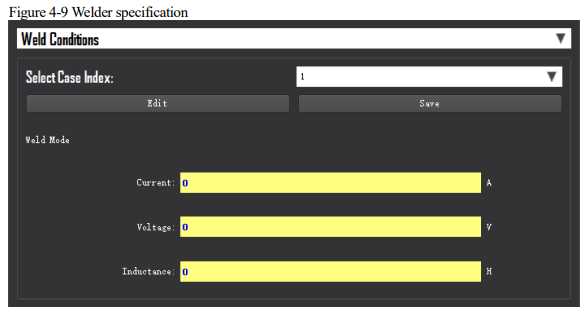
Specifications refer to a set of welding parameter specifications. Use of welding specifications can simplify the application of welding commands.
There are five types of specifications:
⚫ Welding Specification: Invoked by arc striking and arc stopping commands.
⚫ Arc Weave Specification: Invoked by WEAVE command.
⚫ Arc Striking Specification: Invoked by STRIKE command.
⚫ Arc Stopping Specification: Invoked by STOP command.
⚫ Arc Seek Specification: Invoked by Arc Searching command.
When executing arc striking and arc stopping commands, welding range and welding voltage of the specification number can be directly called.
Users need to enter the "Welding Specification" interface to set up various specifications. This software supports a total of 30 specification schemes.
⚫ Current: The magnitude of current for arc striking and arc stopping.
⚫ Voltage: The voltage value for arc striking and arc stopping. For the Separate mode, this is the actual voltage value. For the Unified mode, this is the arc length correction value, representing a percentage calculation based on the base voltage. Its positive/negative values represent the rise/fall of the correction voltage. The magnitude of the value corresponds to a percentage after multiplying it by 10%. For instance, if the value is 1.1, it represents an 11% increase in correction voltage. If the value is -2.3, it indicates a 23% decrease in correction voltage. The default is currently the arc length correction value.
Weave Specification
When executing WEAVE command, you can directly call the predefined WEAVE parameters.
Users need to enter the "Weave Specification" interface to set up various weaving specifications.
This software supports a total of 10 specification schemes, as shown in the figure below
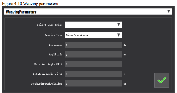
⚫ Weaving Type: There are four options: "No Weaving", "Sine Weaving", "Triangle Weaving", and "Trapezoidal Weaving".
⚫ No Weaving
⚫ Sine Weaving
⚫ Triangle Weaving
⚫ Note: Currently, the default is Sine Weaving.
⚫ Frequency: Frequency of the weaving motion
⚫ Amplitude: Amplitude of the weaving motion
⚫ Rotation Angle around Weaving Plane X-Axis
⚫ Rotation Angle around Weaving Plane Z-Axis
⚫ Peak and Valley Dwell Time
Arc Striking Specification
When executing arc striking commands, you can directly call the predefined arc striking current, arc striking voltage, and pause time.
Users need to enter the "Arc Striking Specification" interface to set up various arc striking specifications. This software supports a total of 30 specification schemes, as shown in the figure below.
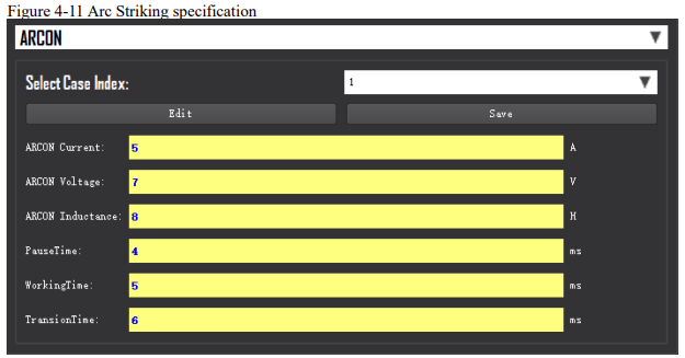
⚫ Arc Striking Current: The magnitude of current for arc striking .
⚫ Arc Striking Voltage: The voltage value for arc striking . For separate modes, this is the actual voltage value. For the Unified mode, this is the arc length correction value, representing a percentage calculation based on the base voltage. Its positive/negative values represent the rise/fall of the correction voltage. The magnitude of the value corresponds to a percentage after multiplying it by 10%. For instance, if the value is 1.1, it represents an 11% increase in correction voltage. If the value is -2.3, If the value is -2.3, it indicates that the correction voltage is reduced by 2.3% of the base voltage. The default is currently the arc length correction value, with a range of - 5~+5.
⚫ Pause Time: The time the welding robot stays at the arc striking point after a successful arc striking.
⚫ Action Time: The duration during which the welding robot's arc striking current is active.
⚫ Transition Time: The time it takes for the welding robot to transition from the arc striking current to the command-set current.
Arc Stopping Specification
When executing arc stopping commands, you can directly call the predefined arc stopping current, arc stopping voltage, and pause time.
Users need to enter the "Arc Stopping Specification" interface to set up various arc stopping specifications. This software supports a total of 30 specification schemes, as shown in the figure below.
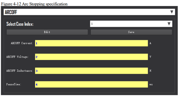
⚫ Arc OFF Current: The magnitude of current for arc stopping.
⚫ Arc OFF Voltage: The voltage value for arc stopping. For separate modes, this is the actual voltage value. For the Unified mode, this is the arc length correction value, representing a percentage calculation based on the base voltage. Its positive/negative values represent the rise/fall of the correction voltage. The magnitude of the value corresponds to a percentage after multiplying it by 10%. For instance, if the value is 1.1, it represents an 11% increase in correction voltage. If the value is -2.3, it indicates that the correction voltage is reduced by 2.3% of the base voltage. The default is currently the arc length correction value, with a range of -5~+5.
⚫ Pause Time: The time the welding robot stays at the arc stopping point after a successful arc stopping.
Welding Adaptation
When executing the welding adaptation function, you can directly call the predefined searching specification.
Users need to enter the "Welding Adaptation" interface to set up various adaptation specifications.
This software supports a total of 30 specification schemes, as shown in the diagram below.
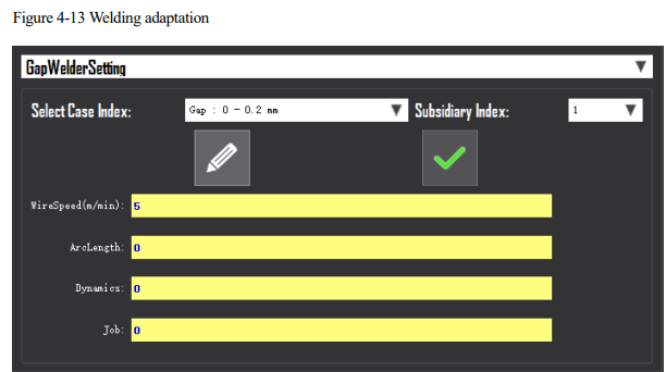
⚫ Adaptation Range: 20 different gap intervals between the welding wire and the weldment, with a numerical range from 0mm to 4mm.
⚫ Scheme Number: Scheme number for welding adaptive control out of the 30 available specification schemes.
⚫ Wire Feed Speed (meters/minute): The speed at which the wire feeder feeds the welding wire, adjusted on-site.
⚫ Arc Length: The arc length, a specification parameter that affects welding quality and requires on site calibration.
⚫ Inductance: A parameter that adjusts the softness or hardness of the arc, calibrated on-site.
⚫ Job Number: A pre-set code for reusable welding parameter configurations. Each code represents a set of welding parameters.
Searching Specification
When executing the Arc Searching function, you can directly call the predefined searching
specification.
Users need to enter the "Searching Specification" interface to set up various searching specifications. This software supports a total of 30 specification schemes, as shown in the diagram
below.
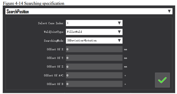
⚫ Weld Seam Type: Fillet weld.
⚫ Searching Mode: Three-dimensional offset and rotation.
⚫ X-Direction Offset Threshold: Users can set this to prevent excessive offset, to avoid collisions. Recommended threshold range: 0mm to 200mm. If it exceeds the set value after executing the offset function, an offset warning will be prompted.
⚫ Y-Direction Offset Threshold: Users can set this to prevent excessive offset, to avoid collisions. Recommended threshold range: 0mm to 200mm. If it exceeds the set value after executing the offset function, an offset warning will be prompted.
⚫ Z-Direction Offset Threshold: Users can set this to prevent excessive offset, to avoid collisions Recommended threshold range: 0mm to 200mm. If it exceeds the set value after executing the offset function, an offset warning will be prompted.
⚫ A+C Offset Threshold: Users can set this to prevent excessive offset, to avoid collisions. Recommended threshold range: 0° to 30°. If it exceeds the set value after executing the offset function, an offset warning will be prompted.
⚫ B Offset Threshold: Users can set this to prevent excessive offset, to avoid collisions. Recommended threshold range: 0° to 30°. If it exceeds the set value after executing the offset function, an offset warning will be prompted.
4.7.3 Welding monitoring
Welding Counting
In the arc welding settings interface, click the "Welding Monitoring" button in the bottom navigation bar to access the welding counting page.
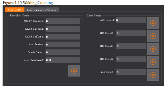
⚫ You can monitor the following parameters on the welding count page: Successful arc stopping count, successful arc striking count, arc interruption count, duration of contact tube usage during arc interruption, total welding count, unsuccessful arc striking count, and collision count.
⚫ You can click the "Clear" button to reset the counts.
Real-time Current and Voltage
The "Welding Monitoring" interface is capable of displaying real-time curves for either "Welding range" or "Welding Voltage", and it provides statistical tracking for "Successful Arc Striking", "Successful Arc Stopping", "Unsuccessful Arc Striking", "Arc Failures", "Collisions" and "Contact Tube Usage Time", as illustrated in figure below.
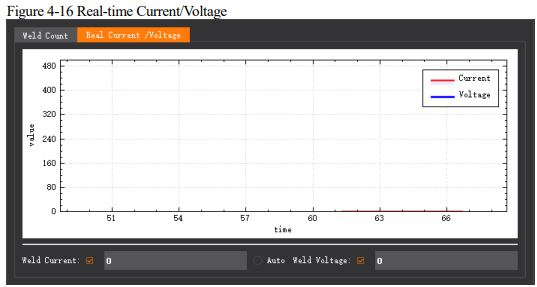
⚫ Welding range: When selected, the curve in the chart will display the current feedback from the welder.
⚫ Welding Voltage: When selected, the curve in the chart will display the voltage feedback from the welder.
4.7.4 Welding diagnostics
Robot and Welder Interaction Interface
Within the arc welding setup interface, click the "Welding Diagnostics" button located in the bottom navigation bar to access the arc welding settings page.
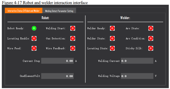
⚫ Robot: Displays command status sent from the robot to the welder, set welding range, and arc length correction value
⚫ Welder: Provides real-time feedback on status, welding range, and welding voltage
Welder Detection Parameter Setting
Used to set the arc striking failure detection time and arc interruption detection time, as shown in figure below.
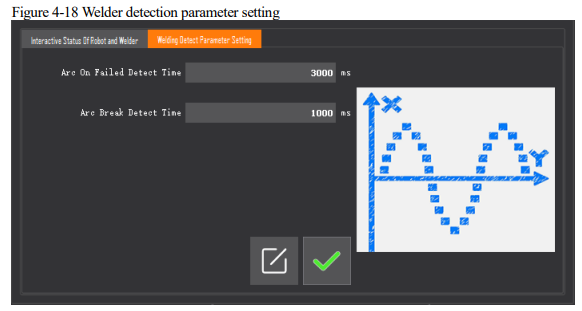
Note: Prior to making changes to the above options, click the "Edit" button, proceed with the modifications, and upon completion, click the "OK" button to finalize the modifications.
4.7.5 Laser tracking
Laser Tracking Welder Specification
Within the arc welding setup interface, click the "Laser Tracking" button located in the bottom navigation bar to access the laser parameter configuration page.
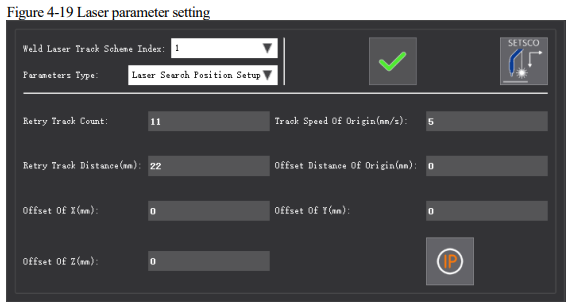
There are three main laser parameters:
1) Laser Searching Parameters
2) Laser Tracking Parameters
3) Laser Type Parameters (supports RENUE and SeamTech lasers)
Laser tracking welding rangely supports two functions: Laser Searching and Laser Tracking
⚫ Laser Positioning: Indicates the laser's search for the starting point of the weld seam.
⚫ Laser Tracking: Indicates real-time laser feedback on the weld' seams position for the robot to track during welding.
These functions are primarily used in two scenarios:
1) Laser finds the starting point of the weld seam, then locates the endpoint of the seam, and subsequently welds from the starting point to the endpoint.
2) Laser finds the starting point of the weld seam, activates the tracking function, and while the laser tracks the seam, the robot performs welding.
When executing laser searching commands, predefined searching and tracking settings can be directly invoked. The software supports a total of 30 predefined schemes.
Searching parameter settings are illustrated in the following figure.
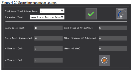
Searching settings explanation:
⚫ Repeat Searching Times (reserved and unused).
⚫ Repeat Searching Distance (reserved and unused).
⚫ X-direction Offset: Added to the weld seam's starting point obtained from the LaserSensor_Search searching command.
⚫ Y-direction Offset: Added to the weld seam's starting point obtained from the LaserSensor_Search searching command.
⚫ Z-direction Offset: Added to the weld seam's starting point obtained from the LaserSensor_Search searching command.
⚫ Starting Point Searching Speed (reserved and unused)
⚫ Starting Point Offset Distance (reserved and unused)
Tracking parameter settings are shown below.
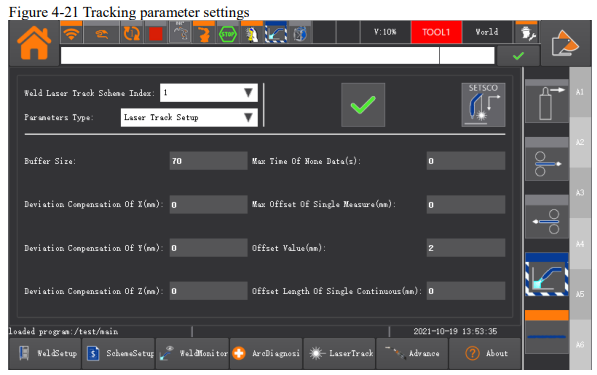
Tracking Parameter Settings Explanation:
1) Buffer Size (reserved and unused);
2) X-direction Deviation Compensation: During the process of tracking the weld seam, this parameter compensates for deviations in the x-direction, measured in millimeters (mm);
3) Y-direction Deviation Compensation: During the process of tracking the weld seam, this parameter compensates for deviations in the y-direction, measured in millimeters (mm);
4) Z-direction Deviation Compensation: During the process of tracking the weld seam, this parameter compensates for deviations in the z-direction, measured in millimeters (mm);
5) Max No-Data Time (reserved and unused);
6) Max Single Measurement Deviation (reserved and unused);
7) Deviation Threshold: Represents the spacing between motion points taken during the tracking process. Default value is 2mm;
8) Max Single Continuous Deviation Length: This parameter indicates the deviation value from the distance between the taught start and end points of the weld seam in the MovLTrack command.
The value has both positive and negative signs.
Laser Parameter Settings
Allows users to define the laser type, as well as the IP address and port of the laser.
In the communication between the laser and the robot, the laser functions as the server while the robot operates as the client. It's essential for the client to be aware of the server's IP address and port number for effective communication.
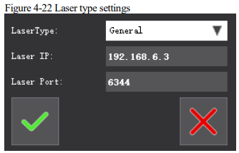
Note: To manipulate the laser parameter setting interface, you need to first click the "Edit" button within the laser searching settings interface.
4.7.6 Laser welding calibration
Laser Calibration Steps
The laser calibration serves a key purpose:
Calibrating the transformation relationship between the laser coordinate system and the robot coordinate system, thus converting the welding seam position identified by the laser into robot coordinates for transmission to the robot.
Prerequisites for Laser Calibration:
⚫ The robot must have undergone accurate calibration to ensure alignment between the tool coordinates and the robot coordinates.
⚫ The laser system should be securely and properly mounted in compliance with the laser system's operational guidelines.
⚫ Personnel conducting the calibration must wear protective eyewear to shield their eyes. Prolonged direct exposure to the laser is to be avoided.
Access the laser welding calibration by clicking the Laser Welding Calibration button in the laser tracking interface, which leads to the laser calibration interface. For detailed information, refer to section 6.15.
4.7.7 Advanced settings
The advanced settings interface encompasses a range of newly developed functionalities, including wire adherence release, external axis coordination, and additional axis encryption.
Within the arc welding settings interface, by clicking the "Advanced Settings" button in the bottom navigation bar, the advanced settings interface is accessed.
Wire Adherence Release Settings
Upon entering the Advanced Settings interface, the default startup page is the wire adherence release configuration page.
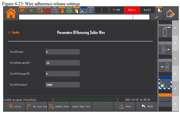
The wire adherence release functionality is presented in the figure.
⚫ Activate or deactivate the feature using the "Enable" checkbox;
⚫ Configure parameters such as "Wire Handling Cycles", "Wire Adherence Release Time", "Wire Adherence Release Voltage", and "Wire Adherence Release Time". Upon completing configurations, click the "Save" button to store the data;
⚫ The "Wire Adherence Release" button allows deactivation of the function.
External Axis Coordination
External axis coordination falls under the advanced functionalities. Detailed information is available in section 6.2.
Additional Axis Encryption
The additional axis encryption is an advanced feature. Further details can be found in section 6.3
4.7.8 Virtual welding
When the welding enable function is disabled or when welding enable is unchecked within the welding settings interface, the virtual welding function is employed. This allows normal execution
of all welding commands, sending current and voltage values for arc striking and OFF to the welder. This aids users in verifying welding parameters. Additionally, the robot can operate independently from the welder, allowing uninterrupted trajectory validation without affecting operations.
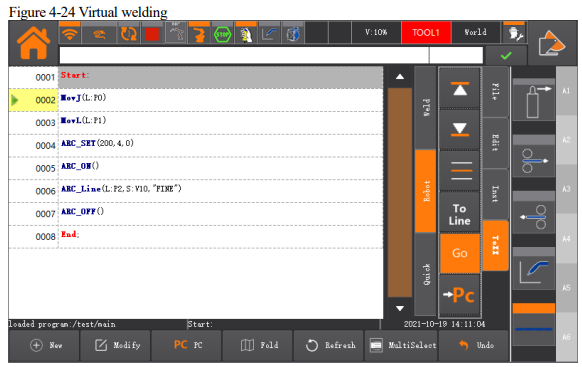
4.7.9 Pause and resume welding
When the "Restart Enable" checkbox within the welding settings interface is selected, welding can be paused during the process and then resumed, allowing the arcing welding to continue from the interruption point.
4.7.10 Help interface
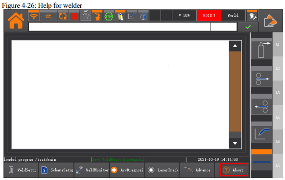
The primary purpose of this interface is to provide users with usage instructions for the welding software, to facilitate their understanding of its main functionalities.
No comments to display
No comments to display