
3. Wiring
3.1 Main Circuit Wiring
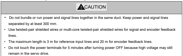
Please observe the following instructions while wiring the main circuit.
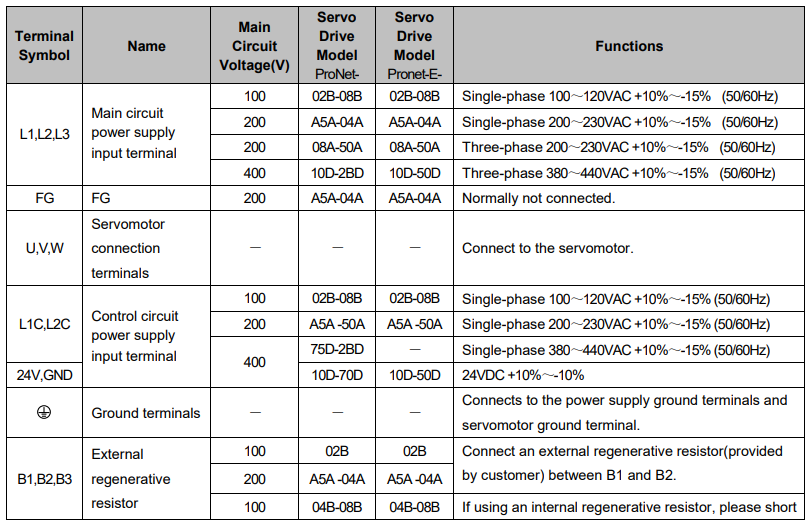
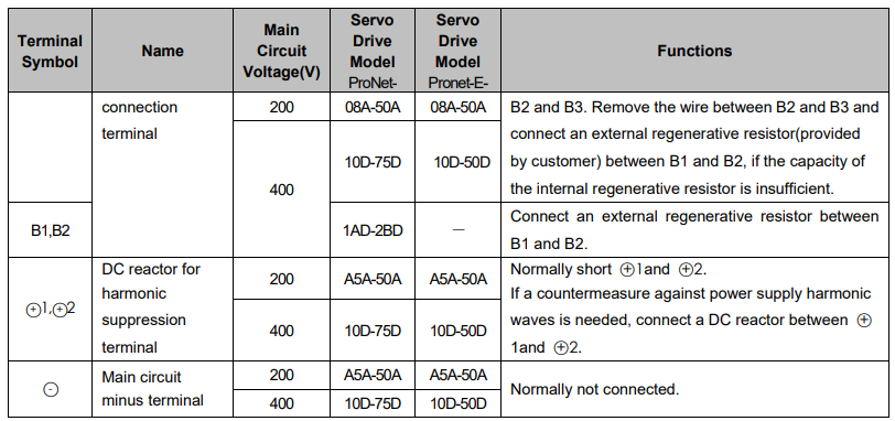
3.1.1 Names and Functions of Main Circuit Terminals
3.1.2 Typical Main Circuit Wiring Examples
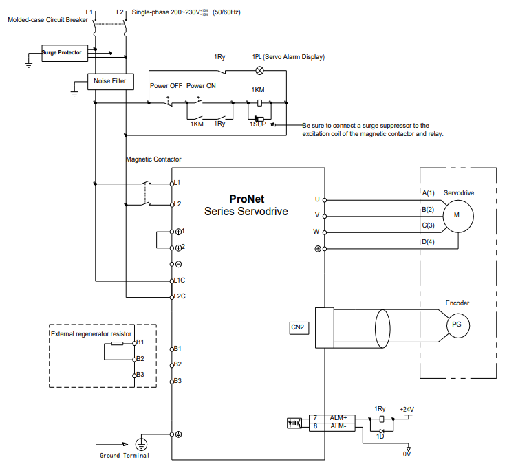
Single-phase 200V ProNet-A5A~04A/ Single-phase 200V ProNet-E-A5A~04A
Note
1.The L1,L2,L3 and L1C,L2C terminals wiring method of ProNet-A5A~04A/ProNet-E-A5A~04A servo drives is different from other ProNet series servo drives. Please note the specific terminal definition while wiring.
2.The main circuit power supply of ProNet-A5A~04A/ProNet-E-A5A~04A is Single-phase 200V.
3. External regenerative resistor for ProNet-A5A~04A/ProNet-E-A5A~04A is provided by customer, the model of 60W,50Ωresistor is recommended.
4.Change Pn521.0 from “1” to “0” when using the external regenerative resistor in ProNet-A5A 04A/ProNet-E-A5A~04A servo drives.
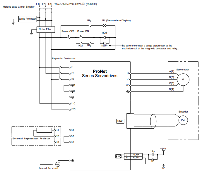
·Three-phase 200V ProNet-08A~50A/ Three-phase 200V ProNet-E-08A~50A
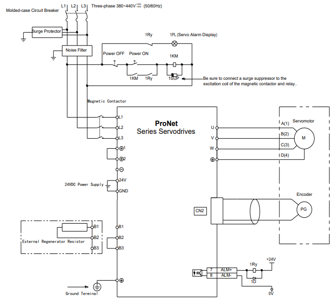
Three-phase 400V ProNet-10D~70D/ Three-phase 400V ProNet-E-10D~50D
Three-phase 400V ProNet-75D~2BD
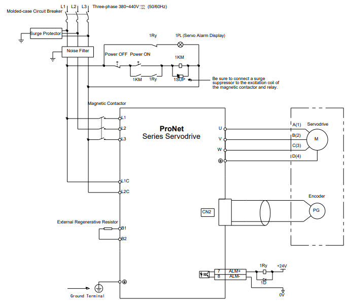
Notes:
1. A resistor value of 1500W/20Ω is recommended for the external regenerative resistor of ProNet 1AD.
2. A resistor value of 1500W/15Ω is recommended for the external regenerative resistor of ProNet-1ED.
3. A resistor value of 1500W/20Ω is recommended for the external regenerative resistor of ProNet-2BD.
Single-phase 100V ProNet-02B /Single-phase 100V ProNet-E-02B
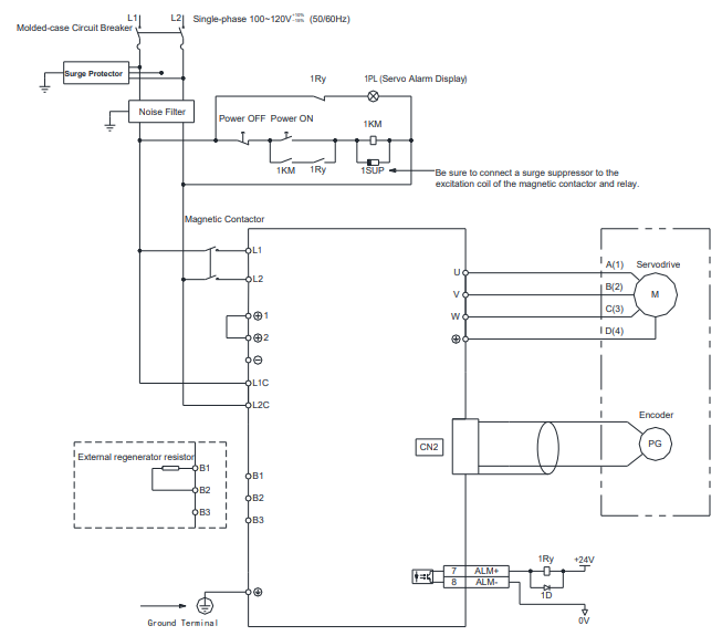
Single-phase 100V ProNet-04B /Single-phase 100V ProNet-E-04B
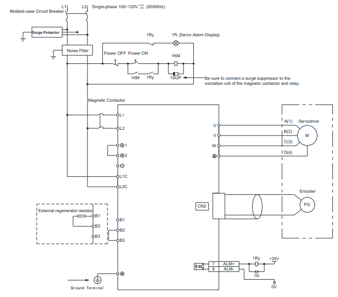
Single-phase 100V ProNet-08B /Single-phase 100V ProNet-E-08B
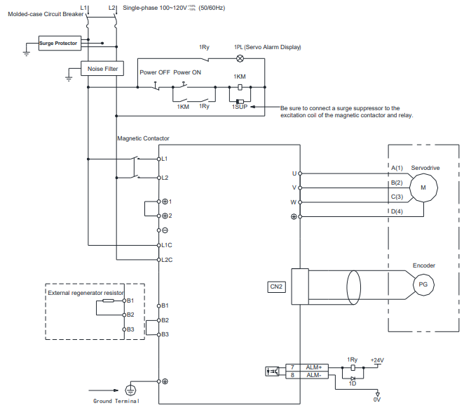
Notes:
When single-phase 100VAC is provided for main circuit on rated speed, instantaneous peak torque≤4.78 N.m.
When three-phase 100VAC is provided for main circuit on rated speed, instantaneous peak torque≤7.16 N.m.
3.2 I/O Signals
3.2.1 Examples of I/O Signal Connections
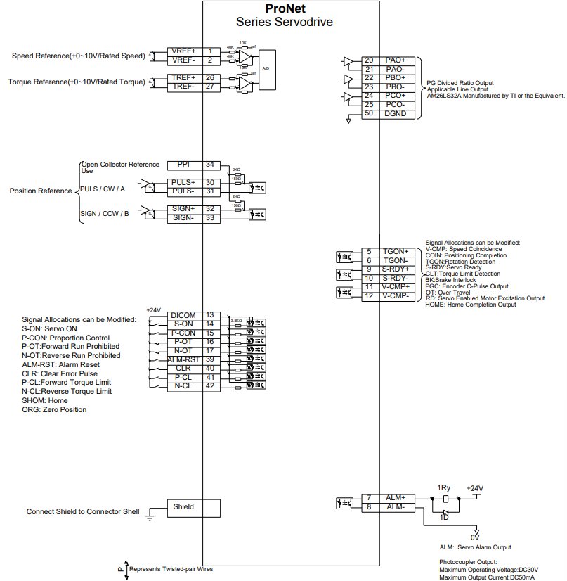
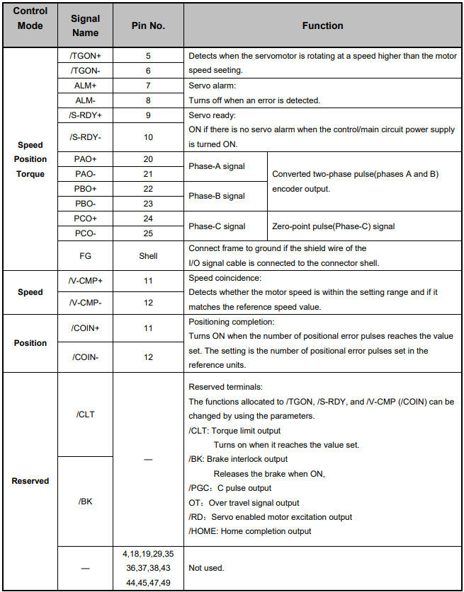
3.2.2 I/O Signal Names and Functions
Input Signals
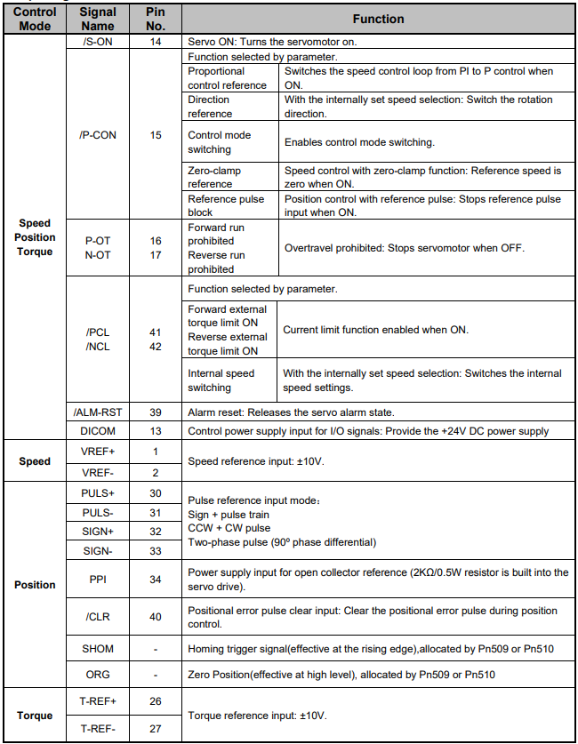
Output signals
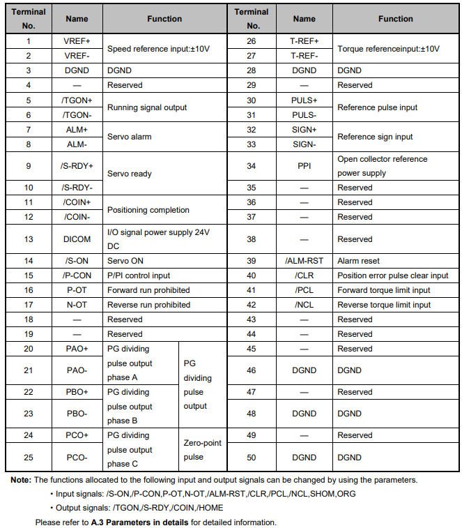
3.2.3 I/O Signal Connector (CN1) Terminal Layout
3.2.4 Interface Circuit
This section shows examples of servo drive I/O signal connection to the host controller.
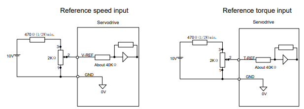
■Interface for Analog Reference Input Circuit
Analog signals are either speed or torque reference signals at about 40kΩ impedance, and the maximum allowable voltages for input signals is ±10V.
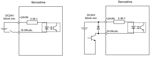
■Interface for Sequence Input Circuit
The sequence input circuit interface connects through a relay or open-collector transistor circuit. Select a low-current relay otherwise a faulty contact will result.
■Interface for Line Driver Output Circuit
The amount of two-phase (phase A and phase B) pulse output signals (PAO,/PAO,PBO,/PBO) and zero-point pulse signals (PCO,/PCO) are output via line-driver output circuits. Normally, the servo drive uses this output circuit in speed control to comprise the position control system at the host controller. Connect the line-driver output circuit through a line receiver circuit at the host controller.
■Interface for Sequence Output Circuit
Photocoupler output circuits are used for Servo Alarm (ALM), Servo Ready(S-RDY), and other sequence output signal circuits. Connect a photocoupler output circuit through a relay circuit.
3.3 Wiring Encoders
3.3.1 Connecting an Encoder(CN2)
■ Wire-saving Incremental Encoder(2500P/R)(Waterproof)
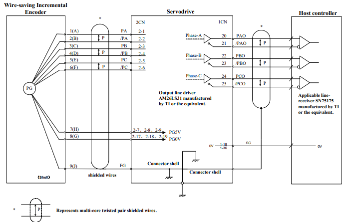
■ Wire-saving Incremental Encoder(2500P/R)(Standard)
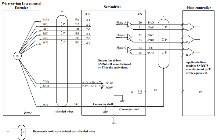
17/20 bit Incremental/Absolute Encoders
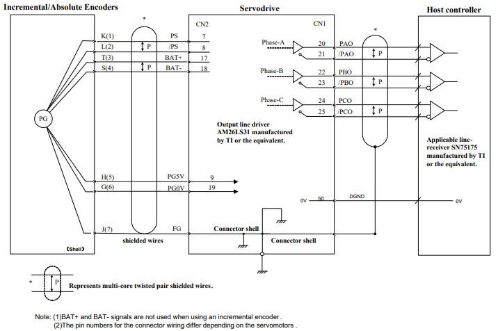
Resolver
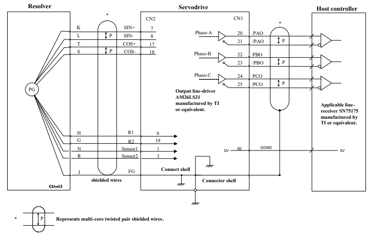
3.3.2 Encoder Connector(CN2) Terminal Layout
Wire-saving Incremental Encoder(2500P/R)

17/20 Bit Incremental/ Absolute Encoder
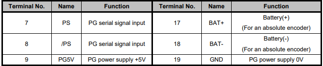
Resolver

3.4 Communication Connection
3.4.1 Communication Connector(CN3) Terminal Layout
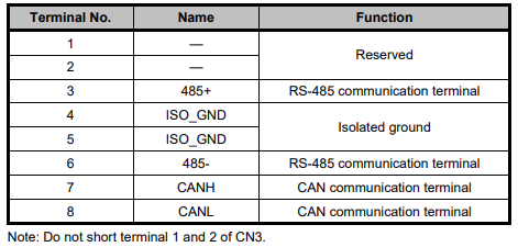
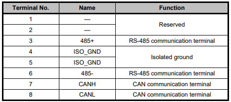
3.4.2 Communication Connector(CN4) Terminal Layout
3.5 Standard Wiring Examples
3.5.1 Single-phase 200V ProNet-A5A~04A/ProNet-E-A5A~04A
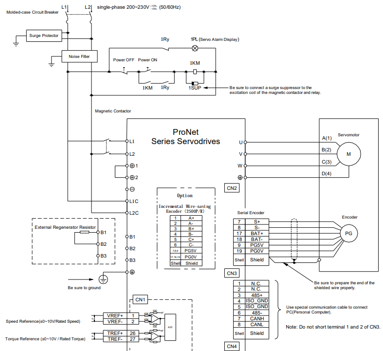
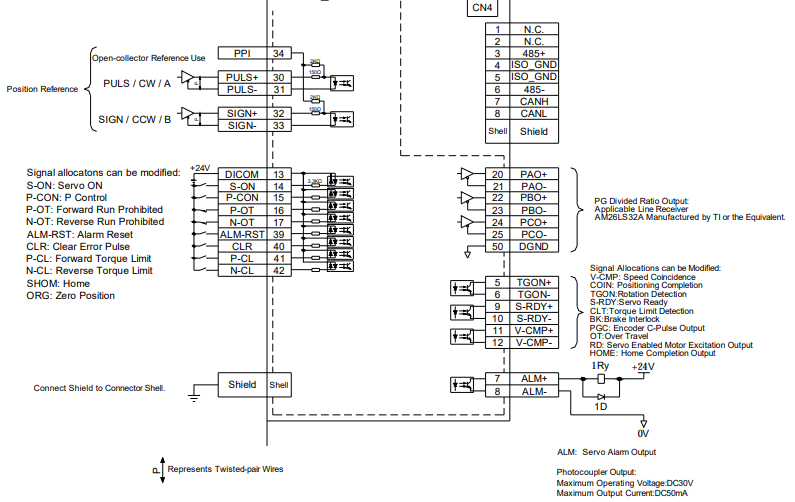
Note 1.The L1,L2,L3 and L1C,L2C terminals wiring method of ProNet-A5A~04A/ProNet-E-A5A~04A servo drives is different from other ProNet series servo drives. Please note the specific terminal definition while wiring.
2.The main circuit power supply of ProNet-A5A~04A/ProNet-E-A5A~04A is Single-phase 200V.
3. External regenerative resistor for ProNet-A5A~04A/ProNet-E-A5A~04A is provided by customer, the model of 60W,50Ωresistor is recommended.
4.Change Pn521.0 from “1” to “0” when using the external regenerative resistor in ProNet- A5A~04A /ProNet-EA5A~04A servo drives.
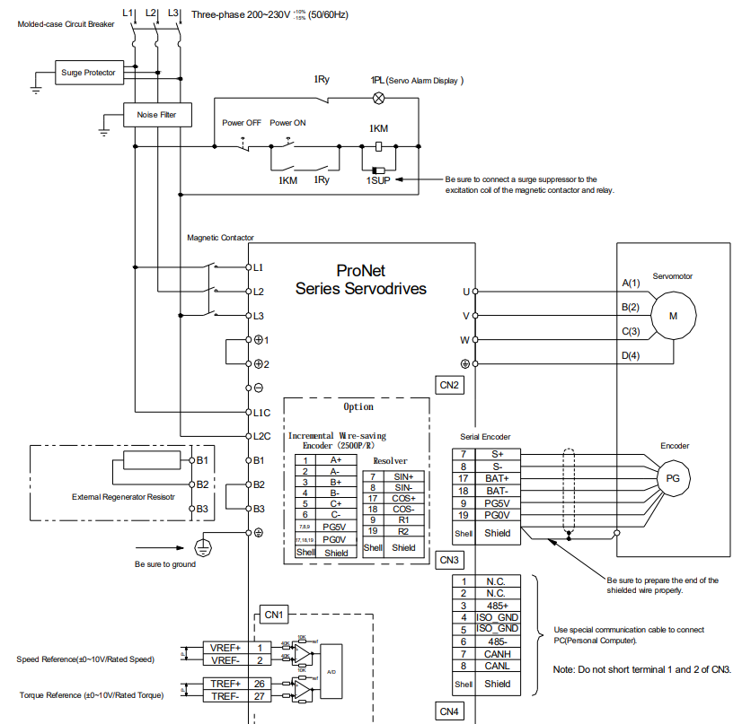
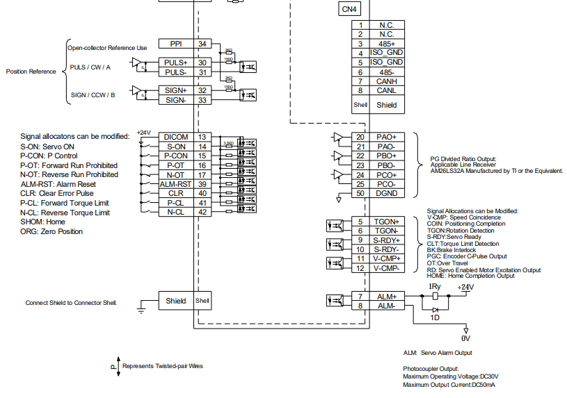
3.5.2 Three-phase 200V ProNet-08A~50A/ProNet-E-08A~50A
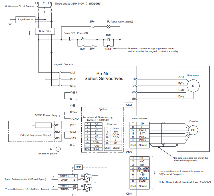
3.5.3 Three-phase 400V ProNet-10D~70D/ProNet-E-10D~50D
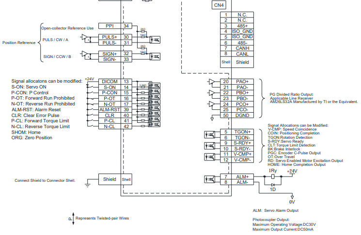
3.5.4 Three-phase 400V ProNet-75D~2BD
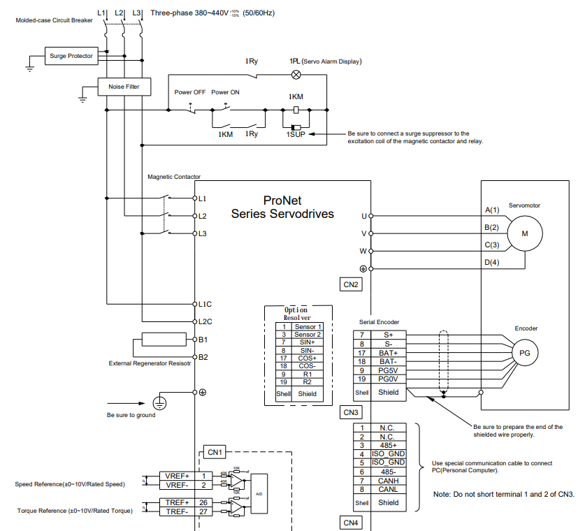
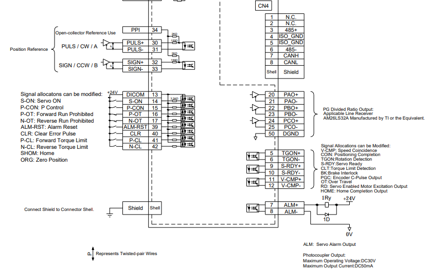
Notes:
1. The resistor of 1500W/20Ω is recommended for the external regenerative resistor of ProNet-1AD.
2. The resistor of 1500W/15Ω is recommended for the external regenerative resistor of ProNet-1ED.
3. The resistor of 1500W/20Ω is recommended for the external regenerative resistor of ProNet-2BD.
3.5.5 Single-phase 100V ProNet-02B/ProNet-E-02B
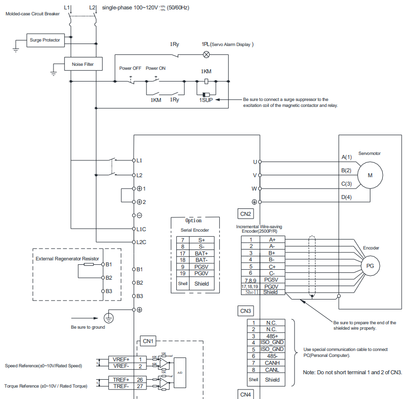
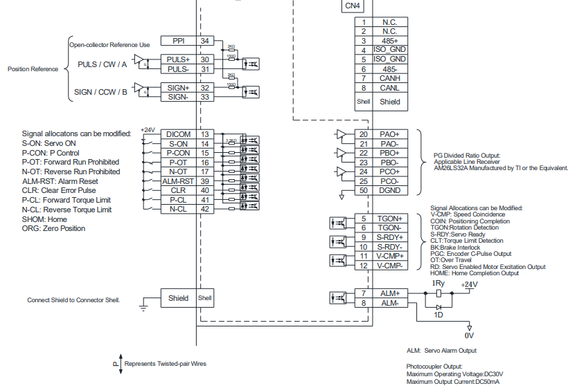
3.5.6 Single-phase 100V ProNet-04B /ProNet-E-04B
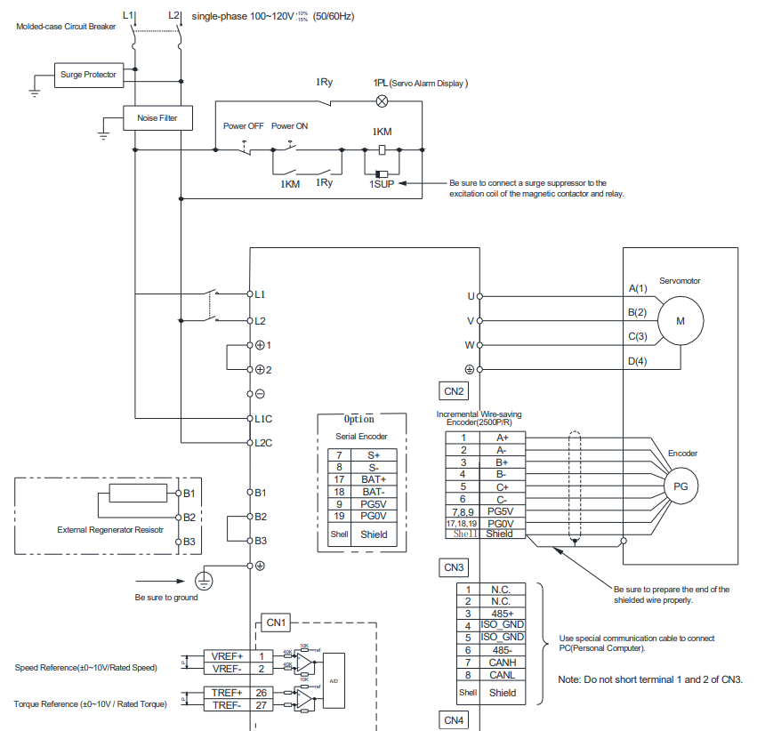
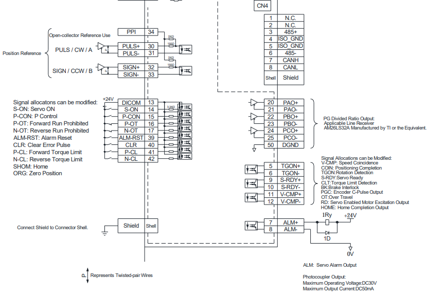
3.5.7 Single-phase 100V ProNet-08B/ ProNet-E-08B
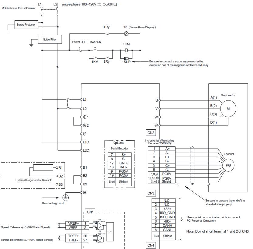
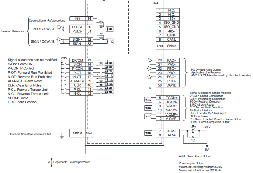
Notes:
When single-phase 100VAC is provided for main circuit on rated speed, instantaneous peak torque≤4.78 N.m.
When three-phase 100VAC is provided for main circuit on rated speed, instantaneous peak torque≤7.16 N.m.
3.5.8 Position Control Mode
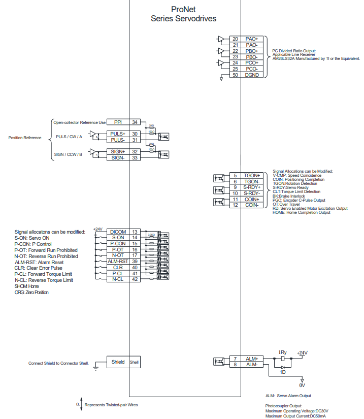
3.5.9 Speed Control Mode
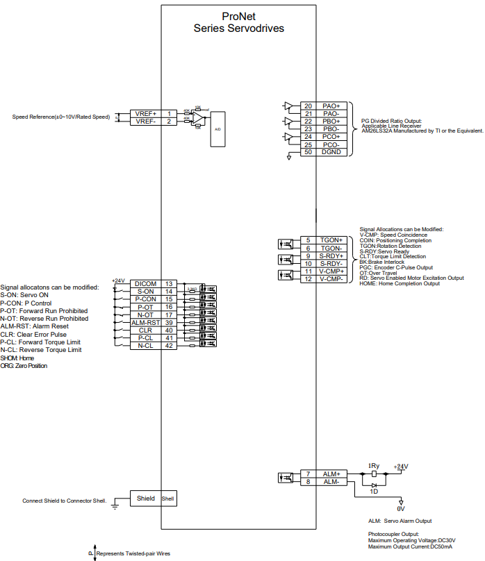
3.5.10 Torque Control Mode
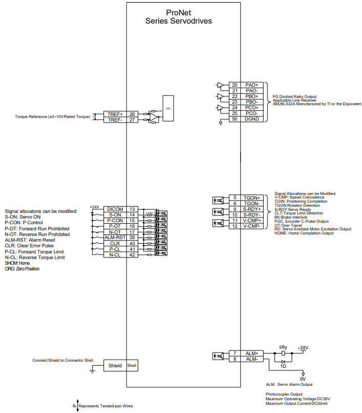
3.6 Wiring for Noise Control
3.6.1 Noise Control
The servo drive uses high-speed switching elements in the main circuit. It may receive "switching noise" from these high-speed switching elements.
To prevent malfunction due to noise, take the following actions:
• Position the input reference device and noise filter as close to the servo drive as possible.
• Always install a surge absorber in the relay, solenoid and electromagnetic contactor coils.
• The distance between a power line (servomotor main circuit cable) and a signal line must be at least 30 cm. Do not put the power and signal lines in the same duct or bundle them together.
• Do not share the power supply with an electric welder or electrical discharge machine. When the servo drive is placed near a high-frequency generator, install a noise filter on the input side of the power supply line. As for the wiring of noise filter, refer to (1) Noise Filter shown below.
• For proper grounding technique, refer to (2) Correct Grounding. (1) Noise Filter
Please install a noise filter in the appropriate place to protect the servo drive from external noise interference.
Notice:
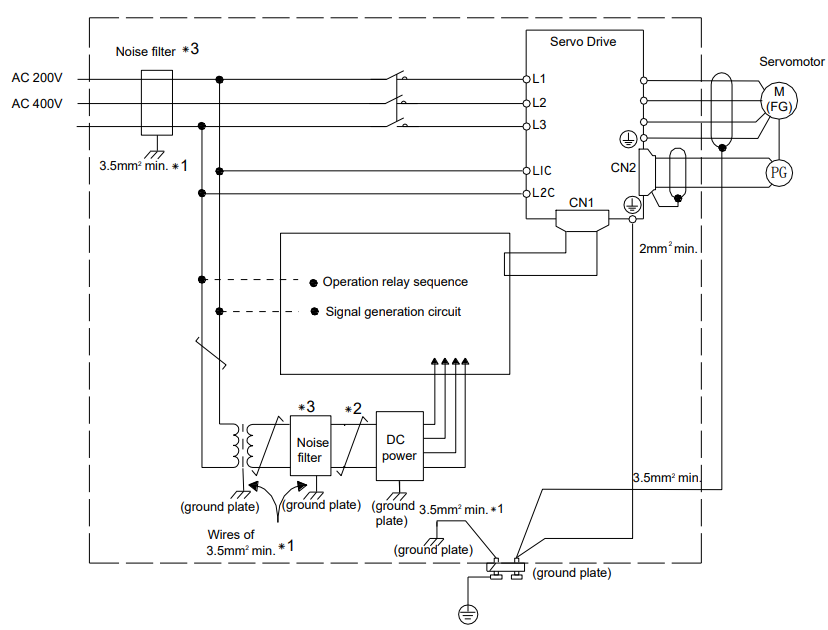
•For ground wires connected to the ground plate, use a thick wire with a thickness of at least 3.5 mm2
(preferably, plain stitch cooper wire)
•  should be twisted-pair wires.
•When using a noise filter, follow the precautions in 3.6.2 Precautions on Connecting Noise Filter.
(2) Correct Grounding
Take the following grounding measures to prevent the servo drive from malfunctioning due to noise.
■ Grounding the Motor Frame
If the servomotor is grounded via the machine, a switching noise current will flow from the servo drive main circuit through the servomotor stray capacitance.
Always connect servomotor frame terminal FG to the servo drive ground terminal. Also be sure to ground the ground terminal .
■ Noise on the I/O Signal Line
If the I/O signal line receives noise, ground the 0 V line (SG) of the reference input line. If the main circuit wiring for the motor is accommodated in a metal conduit, ground the conduit and its junction box. For all grounding, ground at one point only.
(3) Precautions on Installing on the Control Panel
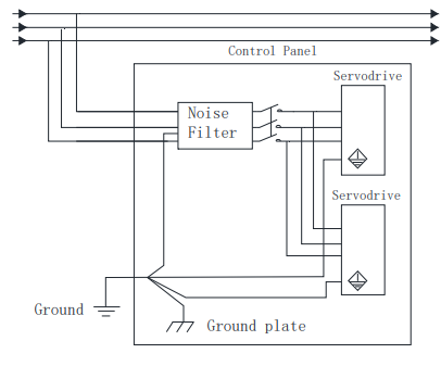
■When the servo drive is installed on the control panel, a piece of metal plate should be fixed. It is used for fixing the servo drive and other peripheral devices. The noise filter should be installed on the metal plate, and closed to the hole drill through power lines on control panel. Use screws to fix the noise filter to the metal plate. The grounding terminals of noise filter connects to the grounding terminals of control panel.
■ Servo drive should be fixed on a piece of metal plate. Make sure the heat sink towards ground. The grounding terminals of servo drive connect to the grounding terminals of control panel.
3.6.2 Precautions on Connecting Noise Filter
(1) Noise Filter Brake Power Supply
Use the noise filter Manufactured by SCHAFFNER at the brake power input for servomotors with holding brakes.
Relationship between servo drive power and noise filter current:
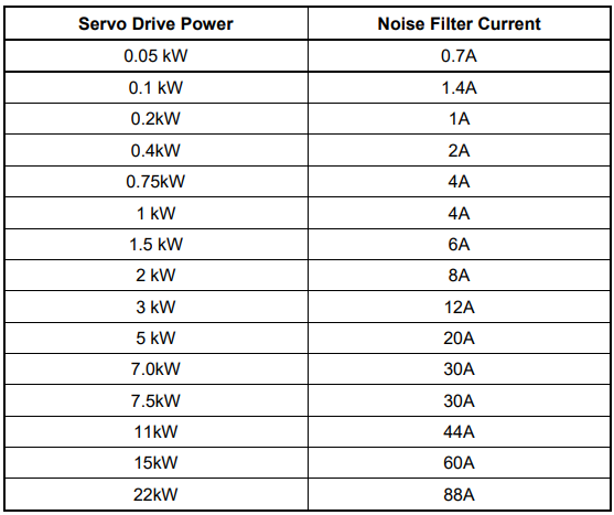
Note:
1. A single-phase servomotor should apply a two-phase filter. A three-phase servo drive should apply a three-phase filter.
2. Choose the right filter according the specifications of operating voltage, current, and manufacturer.
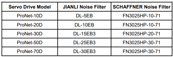
3. Recommended noise filter of 400V servo drive:
(2) Precautions on Using Noise Filters
Do not put the input and output lines in the same duct or bundle them together.
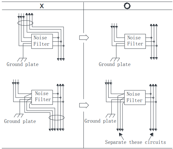
Separate the noise filter ground wire from the output lines.
Do not accommodate the noise filter ground wire, output lines and other signal lines in the same duct or bundle them together.
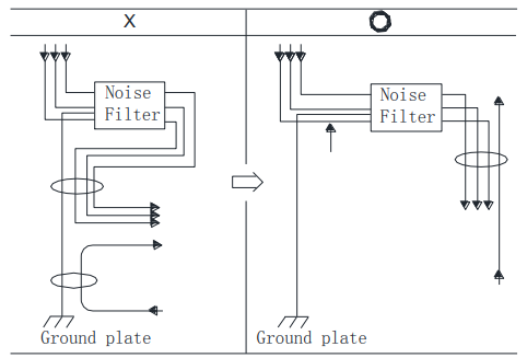
Install the noise filter shield directly to the ground plate. Do not install the noise filter to the painted control panel.
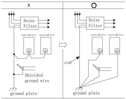
If a noise filter is located inside a control panel, connect the noise filter ground wire and the ground wires from other devices inside the control panel to the ground plate for the control panel first, then ground these wires.
3.7 Installation Conditions of EMC Directives
To adapt a combination of a servomotor and a servodrive to EMC Directives (EN61326-1:2006), the following conditions must be satisfied.
(1) EMC Installation Conditions
This section describes the installation conditions that satisfy EMC guidelines for each servo drive model. This section describes the EMC installation conditions satisfied in test conditions prepared by ESTUN. The actual EMC level may differ depending on the actual system’s configuration, wiring, and other conditions.
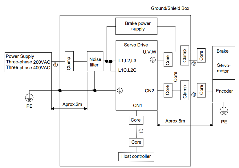
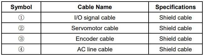
Notes: The example above shows three-phase 200VAC servo drive connection.
(2) Cable Core and Cable Clamp
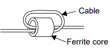
(a) Attaching the Ferrite Core
The diagram shows two turns in the cable.
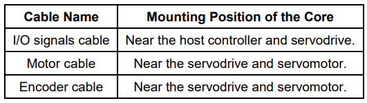
The table shows the cable and the position where the ferrite core is attached.
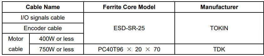
(b) Recommended Ferrite-core
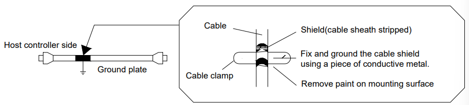
(c) Fixing the Cable
Fix and ground the cable shield using a piece of conductive metal.
• Example of Cable Clamp
(d) Shield Box
A shield box, which is a closed metallic enclosure, should be used for shielding magnetic interference. The structure of the box should allow the main body, door, and cooling unit to be attached to the ground. The box opening should be as small as possible.
3.8 Using More than One Servo Drive
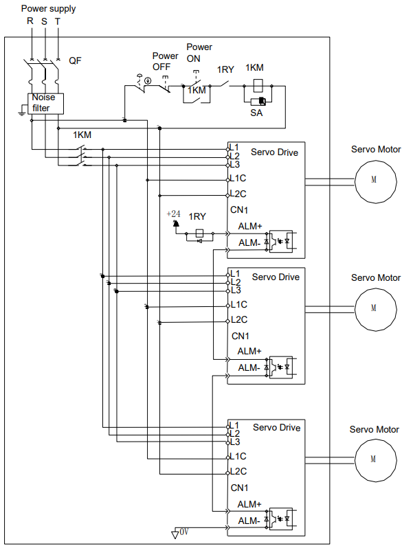
The following diagram is an example of the wiring when more than one servo drive is used.
Connect the alarm output (ALM) terminals for the three servo drives in series to enable alarm detection relay 1RY to operate.
When the alarm occurs, the ALM output signal transistor is turned OFF.
Multiple servos can share a single molded-case circuit breaker (QF) or noise filter. Always select a QF or noise filter that has enough capacity for the total power capacity (load conditions) of those servos.
Notes:
1. Power supply phase-S should connect to ground terminals.
2. The example above shows three-phase 200VAC servo drive connection
3.9 Connecting DC Bus
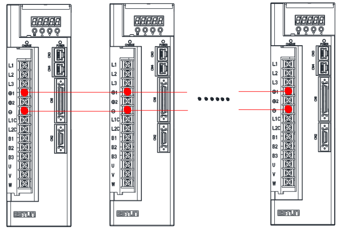
Servo drive wiring includes standard wiring (standard wiring refers to 3.5 Standard Wiring Examples) and optional wiring. Connecting DC bus together of the optional wiring conduces to bus voltage more stable. The following diagram is an example of the wiring when connecting more than one servo drive DC bus.
Notes:
Connecting DC bus together is available only for 200V ProNet and ProNet-E series servo drives. Please use the wiring on ProNet-08A/10A, ProNet-E-08A/10A directly, and inquire customer service before wiring on other products.
No comments to display
No comments to display