
3. Wiring
3.1 Main Circuit Wiring
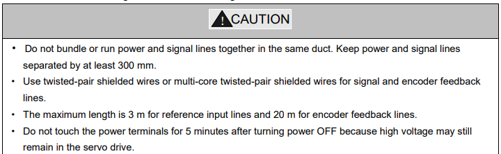
Please observe the following instructions while wiring the main circuit.
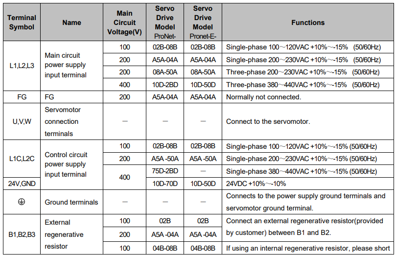
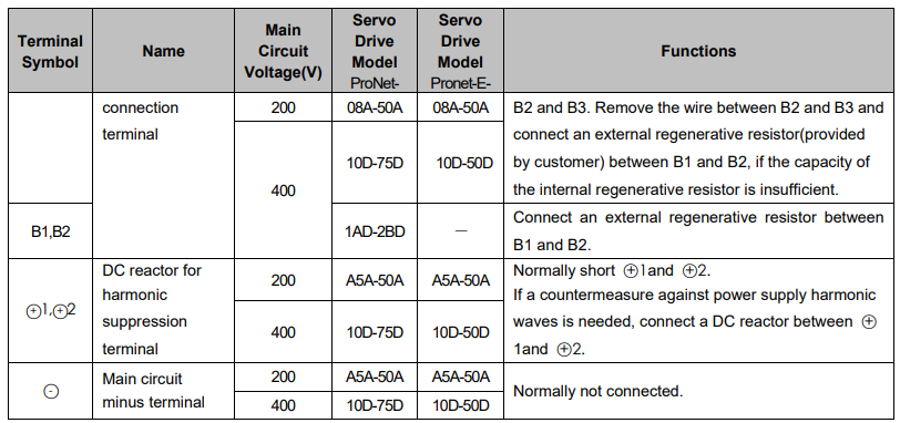
3.1.1 Names and Functions of Main Circuit Terminals
3.1.2 Typical Main Circuit Wiring Examples
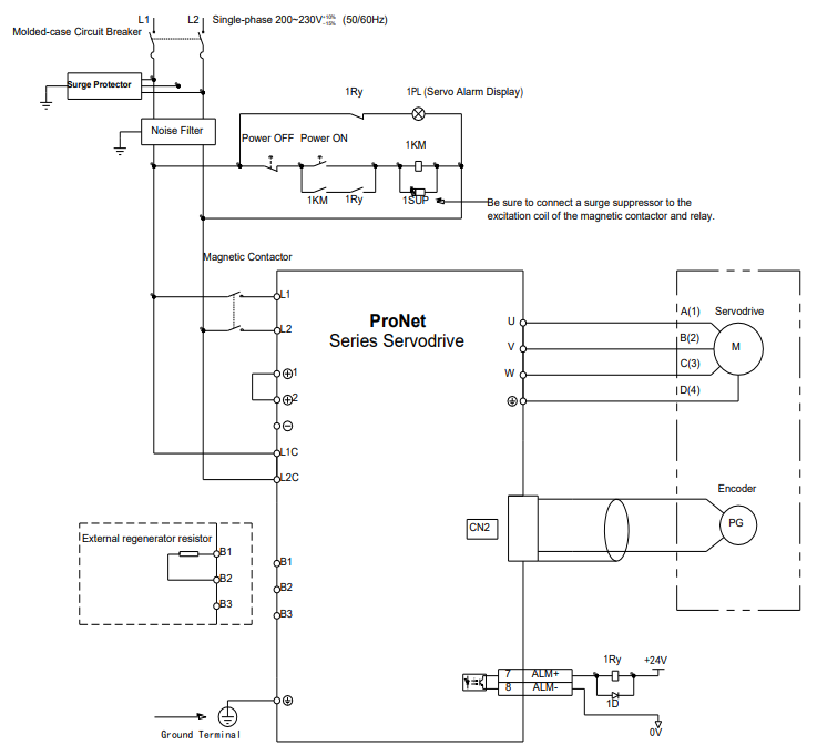
Single-phase 200V ProNet-A5A~04A/ Single-phase 200V ProNet-E-A5A~04A
Note
1.The L1,L2,L3 and L1C,L2C terminals wiring method of ProNet-A5A~04A/ProNet-E-A5A~04A servo drives is different from other ProNet series servo drives. Please note the specific terminal definition while wiring.
2.The main circuit power supply of ProNet-A5A~04A/ProNet-E-A5A~04A is Single-phase 200V.
3. External regenerative resistor for ProNet-A5A~04A/ProNet-E-A5A~04A is provided by customer, the model of 60W,50Ωresistor is recommended.
4.Change Pn521.0 from “1” to “0” when using the external regenerative resistor in ProNet-A5A 04A/ProNet-E-A5A~04A servo drives.
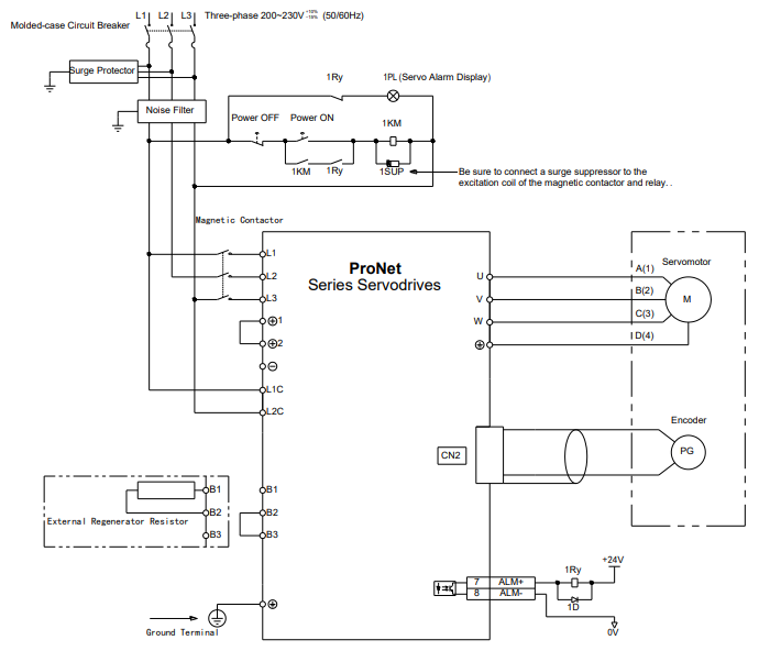
·Three-phase 200V ProNet-08A~50A/ Three-phase 200V ProNet-E-08A~50A
Three-phase 400V ProNet-10D~70D/ Three-phase 400V ProNet-E-10D~50D
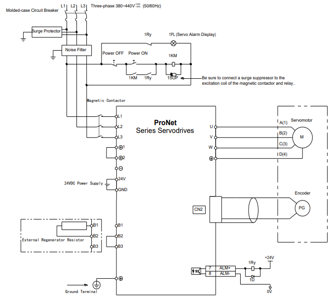
Three-phase 400V ProNet-75D~2BD
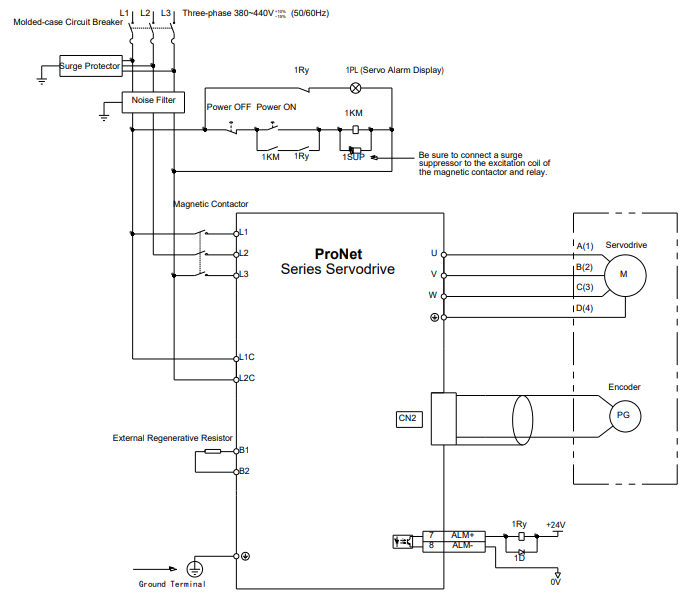
Notes:
1. A resistor value of 1500W/20Ω is recommended for the external regenerative resistor of ProNet 1AD.
2. A resistor value of 1500W/15Ω is recommended for the external regenerative resistor of ProNet-1ED.
3. A resistor value of 1500W/20Ω is recommended for the external regenerative resistor of ProNet-2BD.
Single-phase 100V ProNet-02B /Single-phase 100V ProNet-E-02B
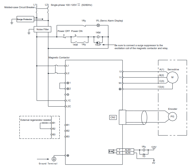
Single-phase 100V ProNet-04B /Single-phase 100V ProNet-E-04B
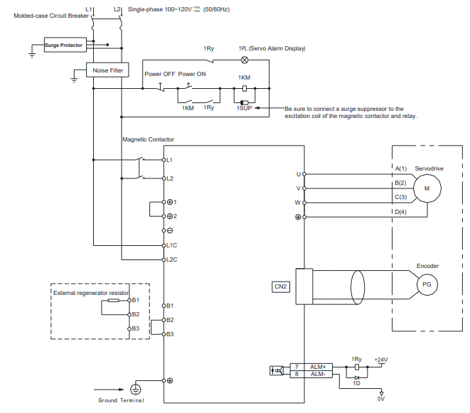
Single-phase 100V ProNet-08B /Single-phase 100V ProNet-E-08B
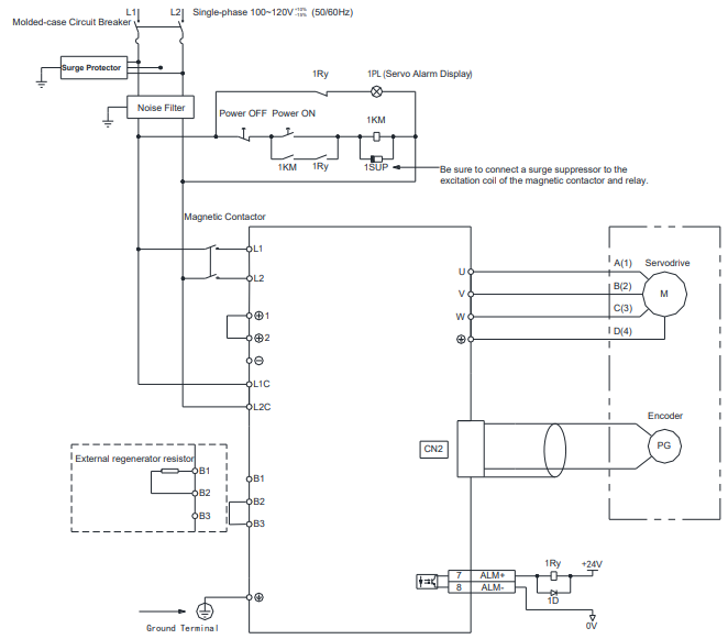
Notes:
When single-phase 100VAC is provided for main circuit on rated speed, instantaneous peak torque≤4.78 N.m.
When three-phase 100VAC is provided for main circuit on rated speed, instantaneous peak torque≤7.16 N.m.
3.2 I/O Signals
3.2.1 Examples of I/O Signal Connections
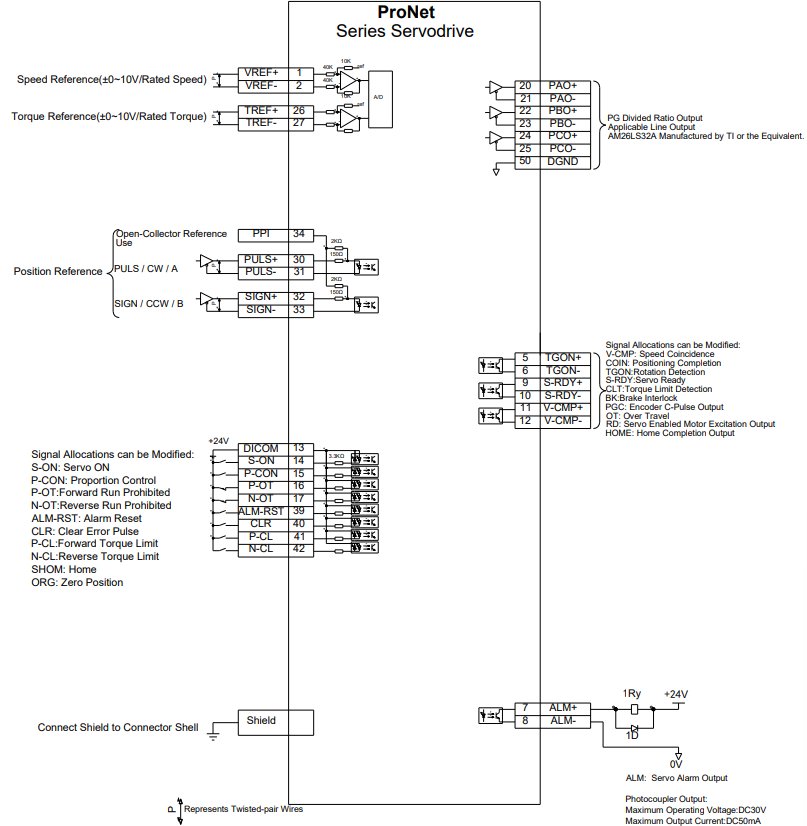
3.2.2 I/O Signal Names and Functions
Input Signals
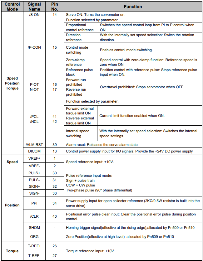
Output signals
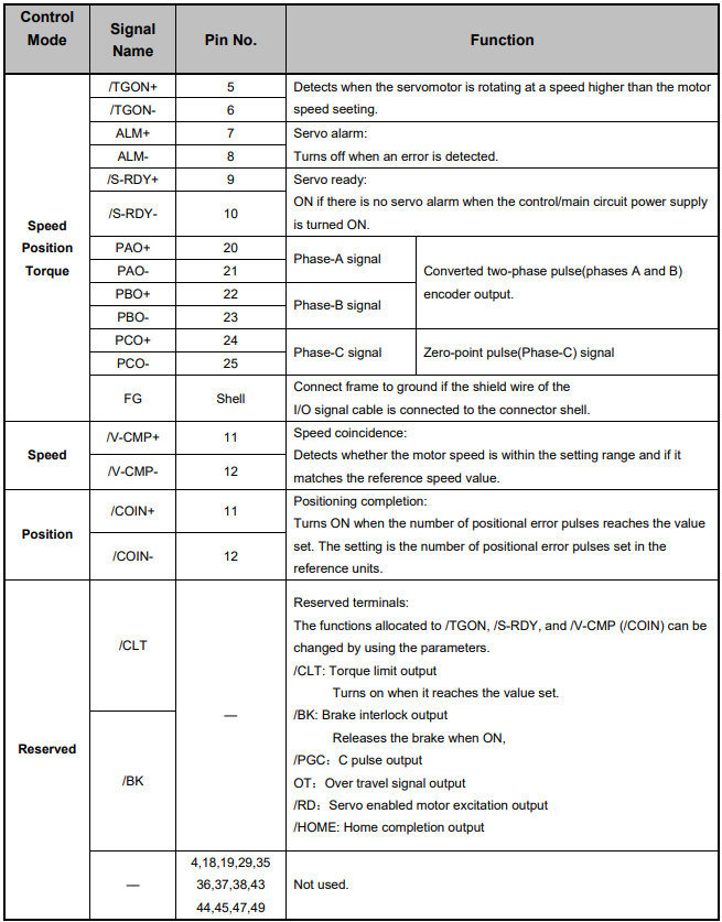
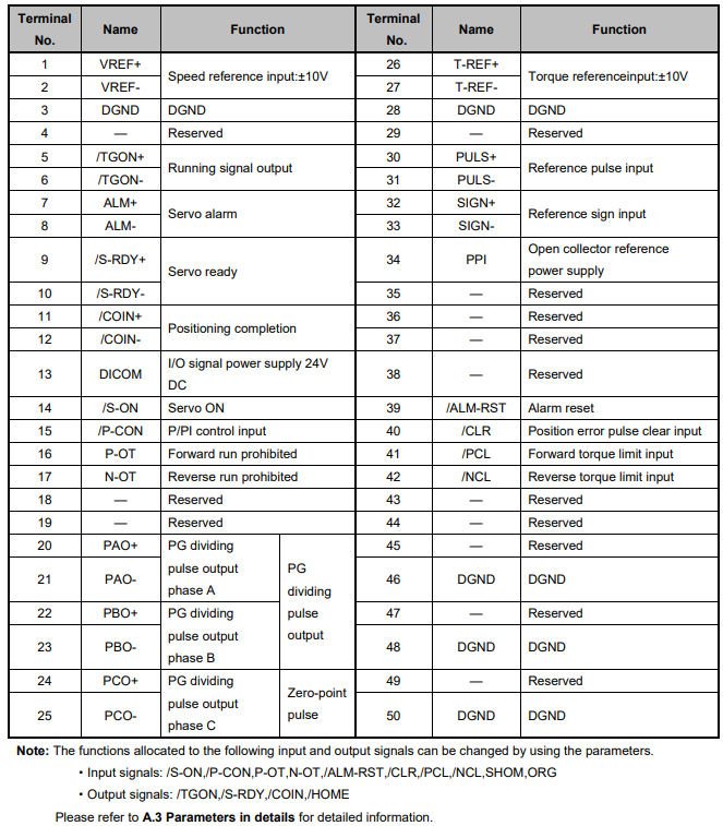
3.2.3 I/O Signal Connector (CN1) Terminal Layout
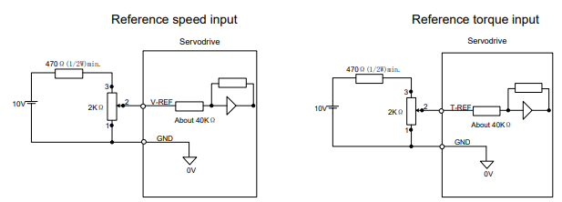
3.2.4 Interface Circuit
This section shows examples of servo drive I/O signal connection to the host controller.
■Interface for Analog Reference Input Circuit
Analog signals are either speed or torque reference signals at about 40kΩ impedance, and the maximum allowable voltages for input signals is ±10V.
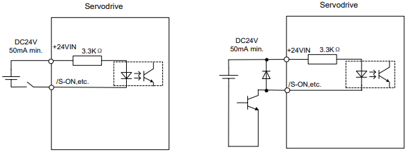
■Interface for Sequence Input Circuit
The sequence input circuit interface connects through a relay or open-collector transistor circuit. Select a low-current relay otherwise a faulty contact will result.
■Interface for Line Driver Output Circuit
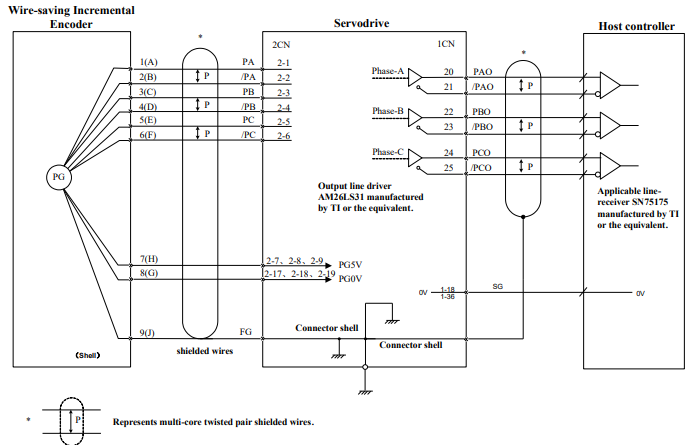
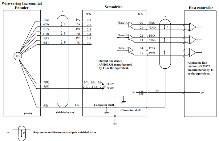
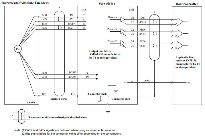
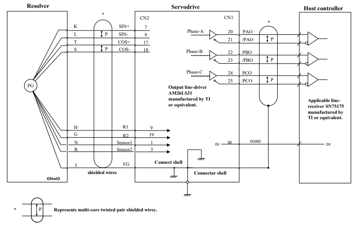
The amount of two-phase (phase A and phase B) pulse output signals (PAO,/PAO,PBO,/PBO) and zero-point pulse signals (PCO,/PCO) are output via line-driver output circuits. Normally, the servo drive uses this output circuit in speed control to comprise the position control system at the host controller. Connect the line-driver output circuit through a line receiver circuit at the host controller.
■Interface for Sequence Output Circuit
Photocoupler output circuits are used for Servo Alarm (ALM), Servo Ready(S-RDY), and other sequence output signal circuits. Connect a photocoupler output circuit through a relay circuit.
3.3 Wiring Encoders
3.3.1 Connecting an Encoder(CN2)
■ Wire-saving Incremental Encoder(2500P/R)(Waterproof)
■ Wire-saving Incremental Encoder(2500P/R)(Standard)
17/20 bit Incremental/Absolute Encoders
Resolver
3.3.2 Encoder Connector(CN2) Terminal Layout
Wire-saving Incremental Encoder(2500P/R)