
4. Wiring & Connection
4.1 Precautions for cable connection
LV cables shall be used to connect between control cabinet and peripheral equipment.
The signal cables of the control cabinet shall be laid in a distance far away from the main power supply circuit, while the HV power supply line shall not be parallel to the signal cables of the control cabinet. Where unavoidable, metal tube or metal slot shall be used to prevent the interference of electric signal. If the cables must be arranged in a cross way, the power cables and signal cables shall be laid in a perpendicular way.
Confirm the socket and cable number to prevent equipment damage arising from incorrect connection.
All non-workers shall be evacuated from the site when connecting cables. Be sure to put all cables in underground cable trench with cover.
Connect the control cabinet's ground wire to the earth for improved EMC performance.
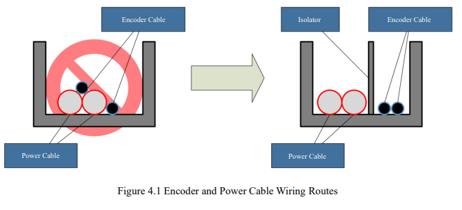
The wiring and routing of encoder cables must be separated from power cables. If they are placed in the same cable conduit, isolators must be used to keep them separated.
4.2 Basic Connection Diagram
The fundamental connection diagram for the control cabinet includes the robot body, control cabinet, teach pendant, surge protector, and circuit breaker.
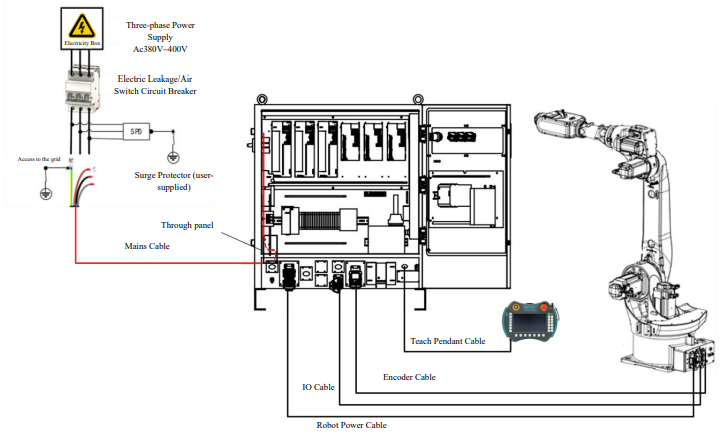
Figure 4.2 Basic Connection Diagram
4.3 Circuit Breaker/Surge Protector Selection
4.3.1 Circuit breaker/Air switch
The robot's motion trajectory involves a repetitive acceleration-deceleration process. As a result, the control cabinet experiences repetitive instances of high transient current in its input. This imposes specific requirements on the rated current and type of upstream circuit breakers or disconnectors. Additionally, being a frequencycontrolled industrial device, the design and operational principles of the robot control cabinet inherently lead to a certain level of leakage current.
ERS-S series CE certification version of the control cabinet circuit breaker/open recommended to use the rated current of 20A D-type circuit breaker, leakage protector recommended to use the sensitivity current ≥ 100mA, B-type leakage protector.
ERS-M series CE certification version of the control cabinet circuit breaker/open recommended to use the rated current of 20A D-type circuit breaker, leakage protector recommended to use the sensitivity current ≥ 100mA, B-type leakage protector.。
The circuit breaker specifications should meet the requirements in the table below.
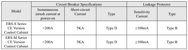
a) It is recommended to provide each robot control cabinet with a circuit breaker/air switch that meets the robot's load current, with a momentary impulse current of 200A during power-up and the ability to cut off a short-circuit current of 5KA. The leakage protection should use a Type B residual current circuit breaker with a sensitivity current ≥100mA.
b) If connecting multiple devices under one circuit breaker or air switch with a leakage protector, the current value and leakage current protection value of the air switch or circuit breaker should be multiplied based on the configuration value of a single unit.
4.3.2 Surge protector
It is advisable to add a suitable surge protector (SPD) at the power input of the control cabinet to meet the requirements of IEC60204-1.
4.4 Power Cable Selection
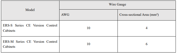
ESTUN control cabinets are not equipped with input power cables. Users need to provide their wiring or purchase from ESTUN. When choosing cables, comply with the relevant safety standards. The recommended cable specifications are as follows.
4.5 Power supply wiring
4.5.1 Description
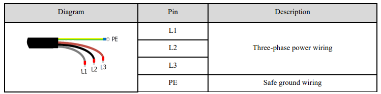
The control cabinet uses a three-phase AC 380V power supply. Follow the provided diagram for proper power cable assembly and correct wiring. Pay attention to the following connections:
4.5.2 Power Harness Assembly
When wiring the power supply cable, please note that it should be routed in the following way as shown in Figure:
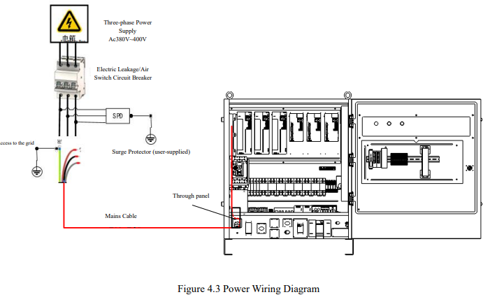
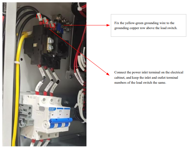
Connect the L1, L2, L3 three-phase power lines from the power grid to the upper space of the load switch inside the control cabinet. Connect the PE line to the grounding bar inside the control cabinet, as shown in Figure 4-4.
4.6 Teach pendant
4.6.1 Precautions for using teach pendant
1. Handle with care and avoid dropping, throwing, or striking the teach pendant, as this may cause damage or malfunction. When not in use, hang it on the dedicated holder to prevent accidental dropping (our internal drop test result is satisfactory at a height of 1 M);
2. Do not use sharp objects such as screws, knives, or pen tips to operate the touch screen. This may damage the touch screen. Use your fingers or a stylus pen to operate the touch screen;
3. When no USB devices are connected, make sure to cover the USB ports with protective caps to avoid exposing them to dust, which could cause interruptions or failures ;
4. When using USB plugs, do not apply excessive force. Normal use is sufficient;
5. If the USB is not recognized, unplug the USB drive, power off, and then plug it back in after powering on;
6. When using the E-stop button or key, do not apply excessive force. Normal use is sufficient;
7. To avoid losing system files,reboot the system at least 2 minutes apart;
8. When storing cables, do not place them under heavy machinery to avoid crushing, cutting, or pulling them apart;
9. Follow our defined wiring guidelines to avoid connection errors and potential issues;
10. The teach pendant is not explosion-proof. Do not use it in explosive environments or work units;
11. Keep the teach pendant away from water, oil, and similar environments;
12. The new T76 teach pendant can be used with all models, while the T72 is only compatible with PNP module control cabinets.
4.6.2 Appearance of teach pendant
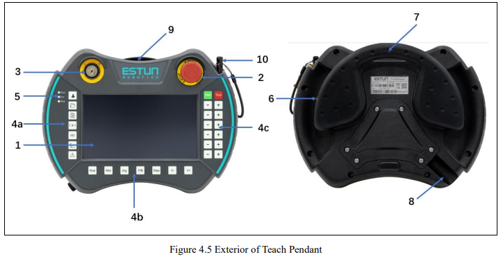
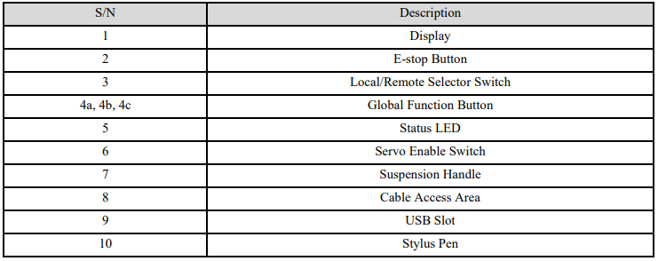
Table 4-1 Description of the Teach Pendant's Interface
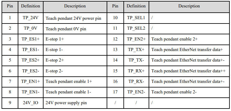
4.6.3 Teach pendant interface definition
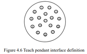
Table 4-2 Teach pendant interface definition
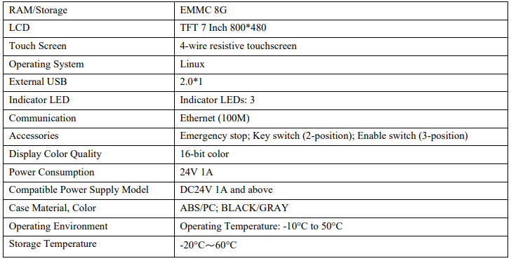
4.6.4 Specificatios of teach pendant

4.7 IOwiring
This section describes the IO interfaces and IO wiring in the ERS Series CE Version of the control cabinet.
The IO modules of the functional safety control cabinets are positioned within the cabinet as illustrated in Figure below.
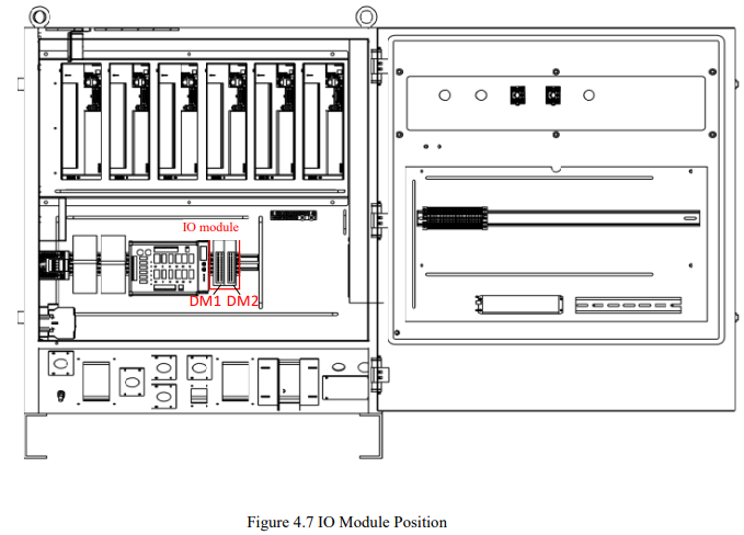
Inside the control cabinet, there are two IO modules labeled DM1 and DM2, each with 16 DIs and 16 DOs. some of the IOs in the DM1 module are occupied by the system and only some are available to the user, while the
16 DIs and 16 DOs in the DM2 module can be used by the user.
If there is not enough IO in ERS-M series CE certified version control cabinet, it can be extended with corresponding IO modules. Due to space constraints, it should be noted that ERS-S series CE certification version of the control cabinet can not be extended IO modules.
4.7.1 System IO
The system IO of ERS series control cabinet occupies 10 channels DI and 9 channels DO, the system IO definition and description are shown in the following table.
Table 4-3 ERS-M Series Control Cabinet System IO Definition and Explanation
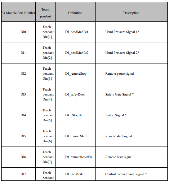
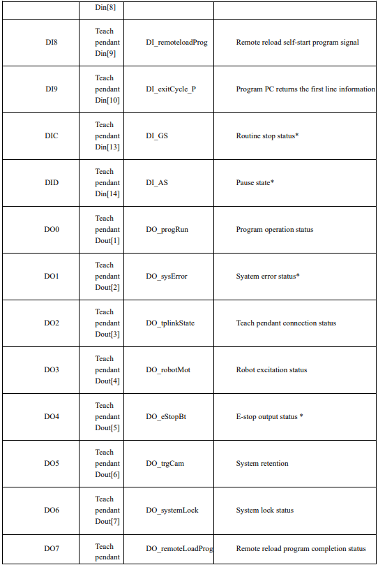

[Note] * on behalf of the control cabinet itself is occupied, the user may not use.
Among the system IOs, DO0 program running status signal can be connected to the external green light, when the robot movement green light, DO1 system error status signal can be connected to the external red light, when the robot issued an alarm red light, DO3 robot excitation status signal can be connected to the external yellow light, when the robot on the enable excitation yellow light. For specific wiring, please refer to "PNP type system DO" or "(Optional) NPN type system DO".
4.7.2 IO Signal specifications
The technical parameters of the digital I/O expansion module EC4-1616BWE are shown in Table below.
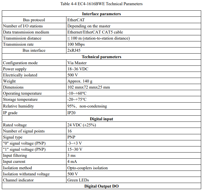
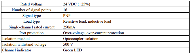
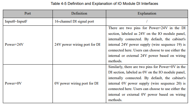
Definition and Explanation of DI Interfaces
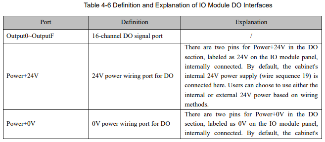
Definition and Explanation of DO Interfaces

4.7.3 System DI and General DI
The system DI and general-purpose DI in the IO module in the control cabinet are wired as follows.
The specific wiring methods for PNP DI are as follows:
(1) Internal 24V power supply wiring
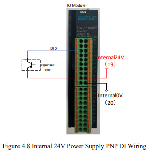
[Note]: When powered by internal 24V, the total load current of all DI and DO modules must not exceed 1A.
(2)External 24V power supply wiring
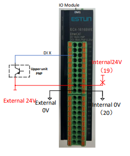 Figure 4.9 External 24V Power Supply PNP DI Wiring
[Note]: When powered by an external 24V source, it's necessary to disconnect the wiring between the 24V on the IO module and the internal 24V (19), as well as between the 0V on the IO module and the internal 0V (20), and ensure proper insulation.

(Optional)The specific wiring methods for NPN DI are as follows:
(1) Internal 24V power supply wiring
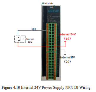
[Note]: When powered by internal 24V, the total load current of all DI and DO modules must not exceed 1A.
(2)External 24V power supply wiring
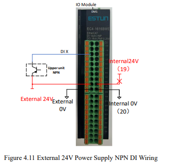
[Note]: When powered by an external 24V source, it's necessary to disconnect the wiring between the 24V on the IO module and the internal 24V (19), as well as between the 0V on the IO module and the internal 0V (20), and ensure proper insulation.

4.7.4 System DO and General DO
The specific wiring methods for PNP DO are illustrated as follows:
(1) Internal 24V power supply wiring
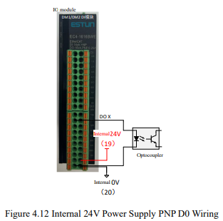 [Note]: When powered by internal 24V, the total load current of all DI and DO modules must not exceed 1A.
(2)External 24V power supply wiring
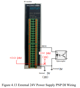
[Note]: When powered by an external 24V source, it's necessary to disconnect the wiring between the 24V on the IO module and the internal 24V (19), as well as between the 0V on the IO module and the internal 0V (20), and ensure proper insulation.
(Optional)The specific wiring methods for NPN DO are as follows:
(1) Internal 24V power supply wiring
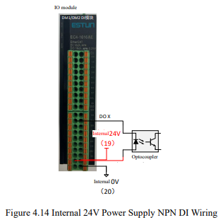
[Note]: When powered by internal 24V, the total load current of all DI and DO modules must not exceed 1A.
(2)External 24V power supply wiring
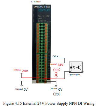
4.7.5 System DO connects to external three-color lamp signal wiring method
In the system IO, DO0 program running status signal can be connected to the external green light, when the robot movement green light on. DO1 system error status signal can be connected to the external red light, when the robot sends out an alarm red light on. DO3 robot excitation status signal can be connected to the external yellow light, when the robot on the enable for excitation yellow light on. The specific wiring is as follows:
PNP DO connects to external three-color lamp signal wiring method
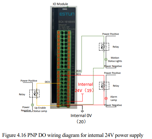
[Note]: If users use external power supply to connect the indicator, you need to choose the appropriate relay and control the load current of the DO module can not exceed 250mA.
(Optional)NPN DO connects to external three-color lamp signal wiring method
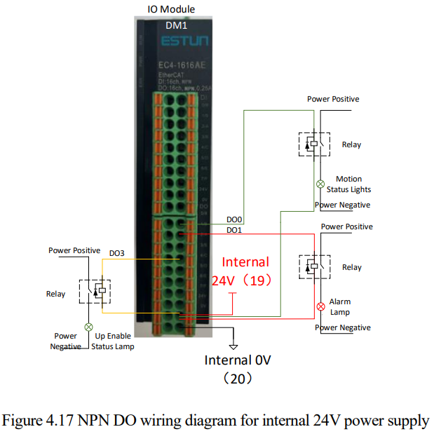
[Note]: If users use external power supply to connect the indicator, you need to choose the appropriate relay and control the load current of the DO module can not exceed 250mA.
4.8 SAFETY IO
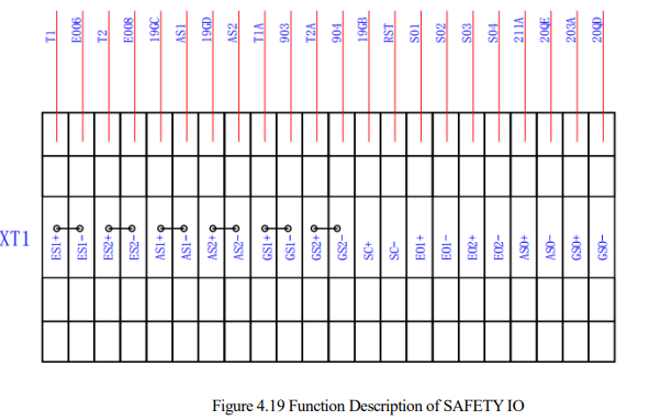
ERS Series CE Version robot control cabinets offer diverse safety stop methods, the specific SAFETY IO is on the XT1 terminal block as shown in Figure 4.22 below.
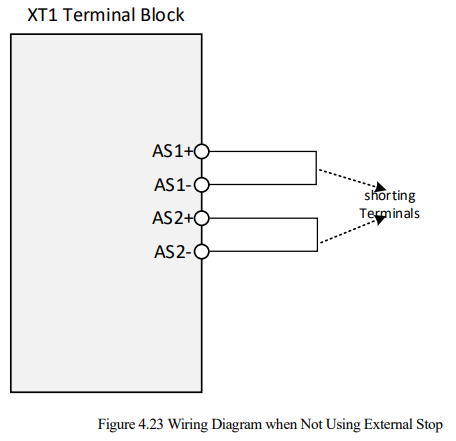
By default, shorting jumpers are inserted into the XT1 terminal, rendering the corresponding functions inactive. To use these functions, the respective shorting jumpers must be removed, and connections must be estaed following the appropriate wiring methods.
It is strongly advised not to remove the shorting jumpers if these functions are not in use, as doing so may trigger the corresponding functionalities, leading to operational halts or alarms.
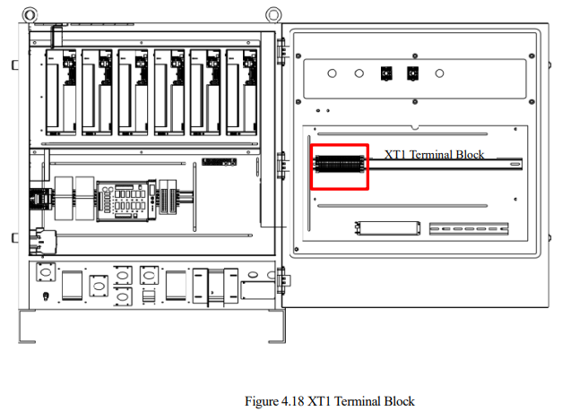
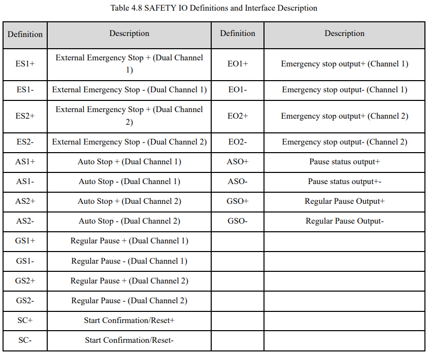
The input/output signals and functionalities related to safety stop are detailed in Table 4.8 below:
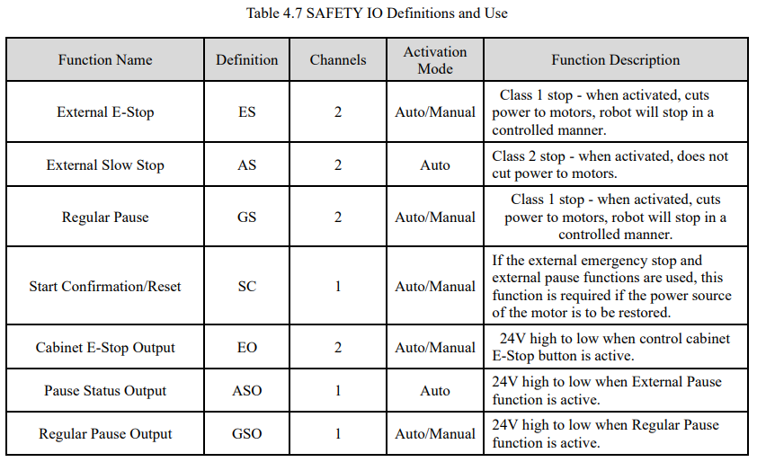
4.8.1 SAFETY IO interface specification
The input/output signals and functionalities related to safety stop are detailed in Table 4.9 below:
[Note]: SAFETY IO is prohibited for driving external loads!
4.8.2 External E-stop wiring method
The External E-Stop function allows users to trigger an emergency stop away from the control cabinet, akin to the functionality of the E-Stop button on the cabinet. Users can incorporate a self-provided E-stop button into the circuit.
The specific wiring method is depicted in Figure:
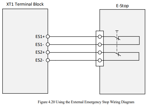
If you use a dual-channel external emergency stop, you need to remove the external shorting tabs, connect the upper end of one circuit of the pushbuttons to ES1+ and the lower end to ES1-; the upper end of the other circuit is connected to ES2+ and the lower end is connected to ES2-, so that it becomes a circuit to be energised and can be operated.
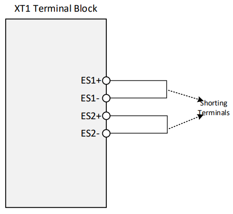 Figure 4.21 Wiring Diagram for Not Use of External E-Stop
4.8.3 External Stop wiring method
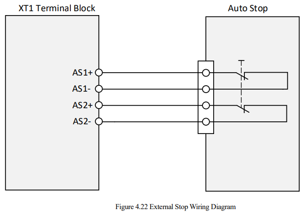
The external Stop function allows stopping the robot's motion during operation, used as safety doors or light curtains. It's employed to secure protective barriers or doors during robot operation. The wiring method is shown in the diagram below.
4.8.4 Start Confirmation/Reset wiring method
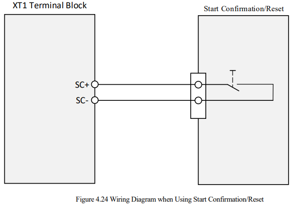
When using the Start Confirmation/Reset function, the SC signal is externally connected to a self-resetting normally open switch. Pressing the Start Confirmation/Reset button allows the control cabinet to provide power to the motors. The specific wiring method is depicted in the following diagram.
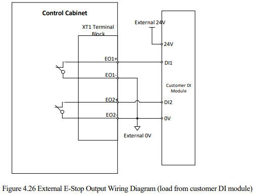
4.8.5 E-Stop Output wiring method
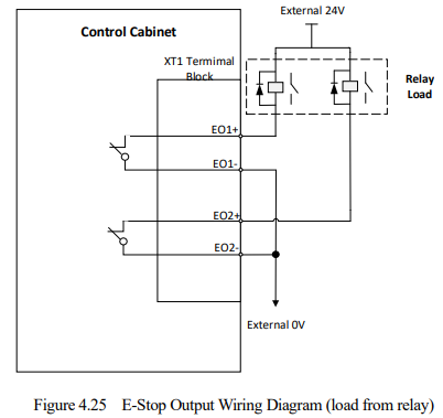
The E-Stop Output refers to the output signal of the External E-Stop function on SAFETY IO. The wiring methods are depicted in the figures below:
(1) Wiring method for a relay load

(2) Wiring method for a customer DI module load:

4.8.6 Pause Status Output wiring method
The pause state output refers to the output signal of the external pause function on the SAFETY IO and is wired as shown below.
(1) Wiring method for a relay load
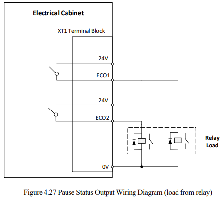
(2) Wiring method for a customer DI module load
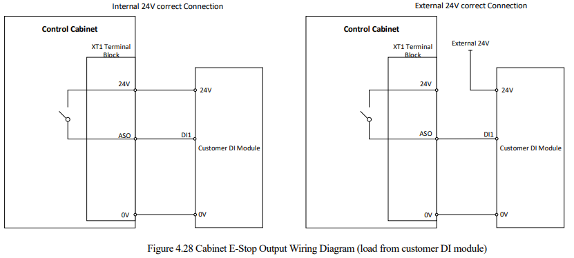
Note: The load current of all DI and DO modules must not exceed 1A when powered by the internal 24V power supply

4.8.7 Regular Pause Status Output wiring method
The Regular Pause Status Output refers to the output signal of the regular stop function on SAFETY IO, if any one of the regular stop signals is in effect, the GSO will change from 24V high level to low level. The wiring is shown in the following figure.
(1) Wiring method for a relay load
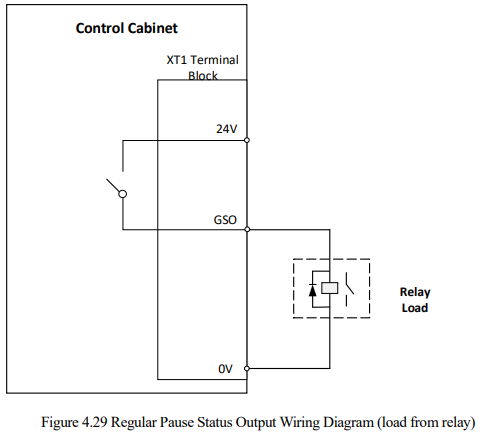
(2) Wiring method for a customer DI module load
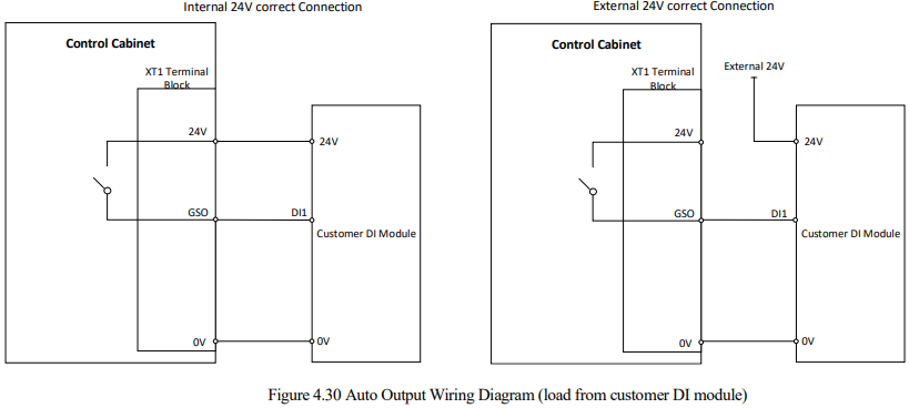
Note: The load current of all DI and DO modules must not exceed 1A when powered by the internal 24V power supply.

4.9 Controller
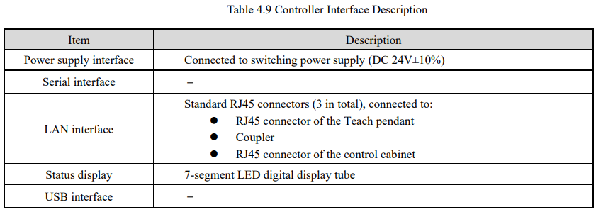
4.9.1 Controller Interface Description
The controller is the motion control device of the robot system, which receives instructions from the teach pendant and sends control signals. It is the core component of the system.
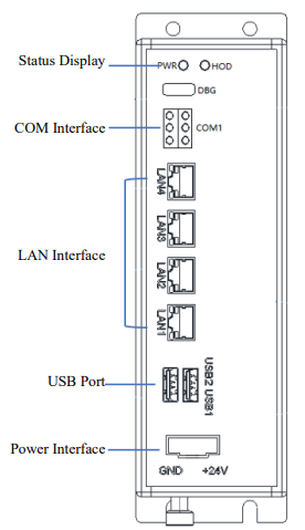
Figure 4.31 Controller Schematic
4.9.2 Communication connections
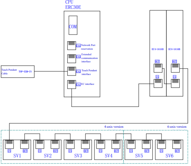
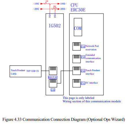
Figure 4.32 Communication Connection Diagram
4.10 Relay Module
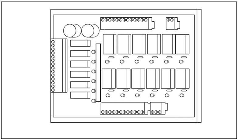
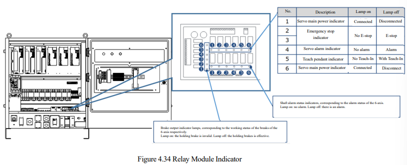
The relay module in the control cabinet integrates 18 LED indicators, which can indicate the current status in detail and provide guidance for the maintenance of the wiring inside the control cabinet.
No comments to display
No comments to display