
3. I/O Wiring
3.1 Input Signal
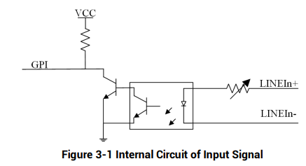
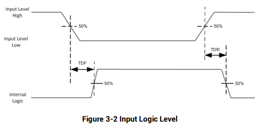
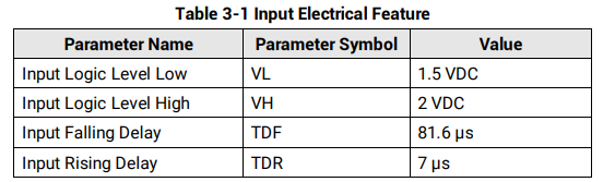
The device's LineIn 0/1/2 is opto-isolated input, and their internal circuit is as follows

3.2 Output Signal
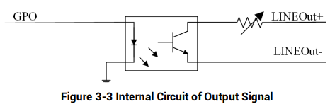
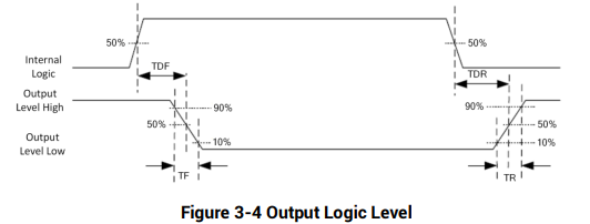
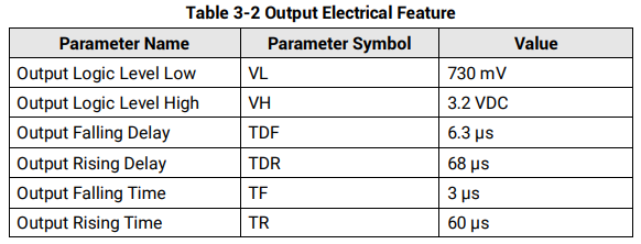
The device's LineOut 0/1/2 is opto-isolated output, and their internal circuit is as follows.


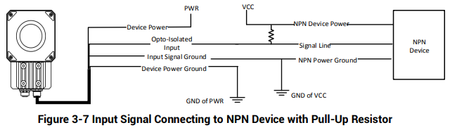
3.3 Input Signal Wiring
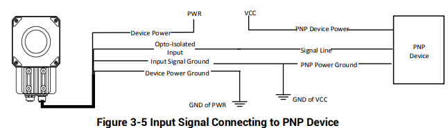
The device can receive external input signal via I/O interface, and here we take LineIn 0 and type I device as an example to introduce input signal wiring.

PNP Device
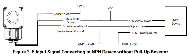
NPN Device
If the VCC of NPN device is 12 VDC or 24 VDC and pull-up resistor is not used, its wiring is as follows
If the VCC of NPN device is 12 VDC or 24 VDC and 1 KΩ pull-up resistor is used, its wiring is as follows.
3.4 Output Signal Wiring
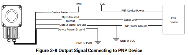
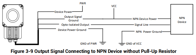
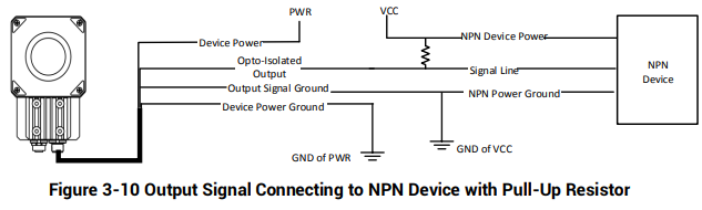
The device can output signal to external device via I/O interface, and here we take LineOut 0 and type I device as an example to introduce output signal wiring.

PNP Device
NPN Device
If the VCC of NPN device is 12 VDC or 24 VDC and pull-up resistor is not used, its wiring is as follows.
If the VCC of NPN device is 12 VDC or 24 VDC and 1 KΩ pull-up resistor is used, its wiring
is as follows.
3.5 RS-232 Serial Port
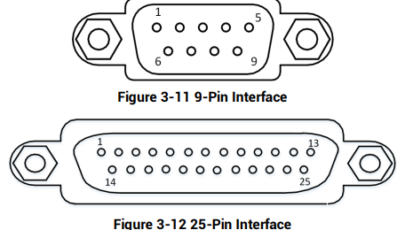
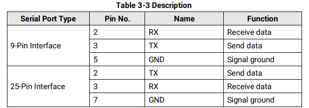
The device supports output via RS-232 serial port. The 9-pin male connector and 25-pin male connector are commonly used serial ports, as shown below. You can refer to the table below for the specific pin name and function
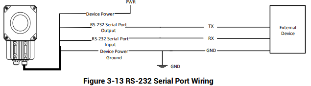
You can refer to the serial port wiring below to connect the device with an external device
No comments to display
No comments to display