
4. Installation
4.1 Installation Preparation
You need to prepare the following accessories before installation.
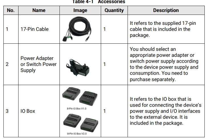
Note
● The type of the IO box may differ by the device model. Please refer to the actual one.
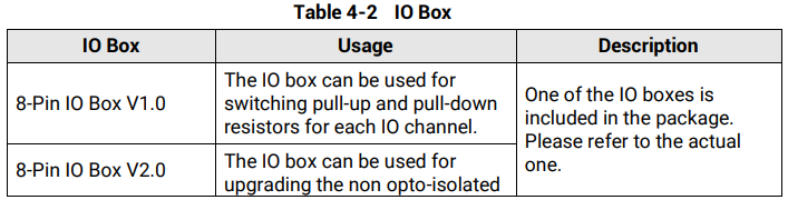

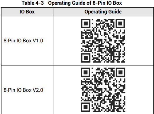
● You can scan the QR codes below to get the Operating Guide of 8-Pin IO Box.
4.2 Install Device
4.2.1 17-Pin Interface and 17-Pin M12 Cable
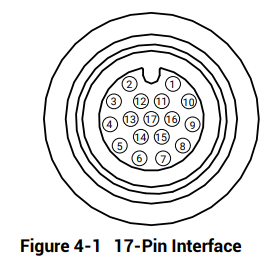
The device has a 17-pin M12 interface for providing power, digital I/O, Ethernet, and serial port.
4.2 Install Device
4.2.1 17-Pin Interface and 17-Pin M12 Cable
The device has a 17-pin M12 interface for providing power, digital I/O, Ethernet, and serial port.
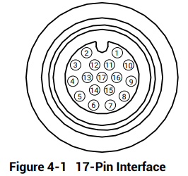
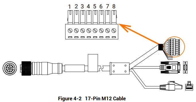
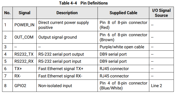
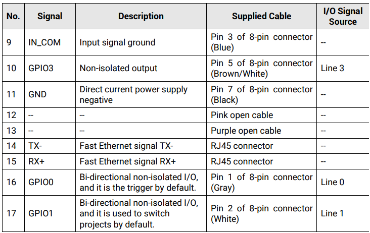
The supplied cable is a 17-pin M12 cable to 8-pin connector, RJ45, and DB9. The cable has converted the pins of device interface for power supply, digital I/O, RS-232 and data communication into the 8-pin connector, RJ45 network interface, and DB9 serial port.

4.2.2 Device Wiring
You can use the supplied 17-pin M12 cable to wire the device.
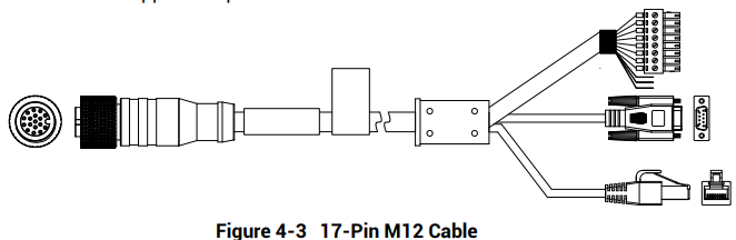
● 17-Pin M12 Interface: Connect the 17-pin M12 female interface to the 17-pin M12 male interface.
● 8-Pin Connector:
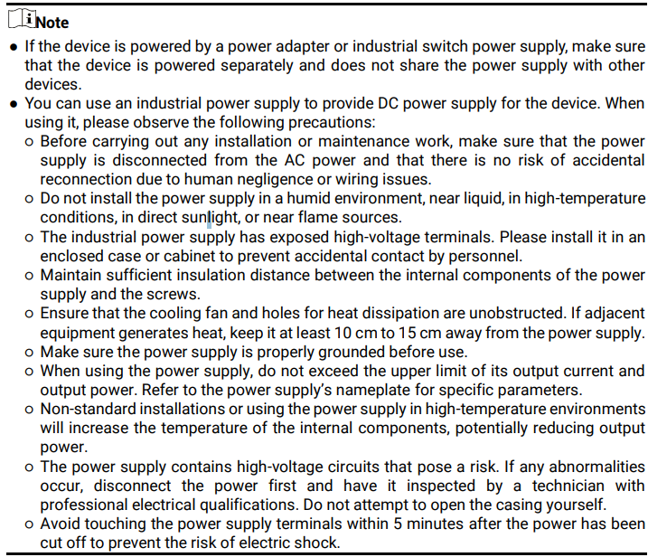
○ If the 8-pin IO box is not used, you can connect to the power adapter or switch power supply via the 8-pin connector (pin 7 and pin 8). For the I/O function, connect to the external device via other pins of the 8-pin connector. Refer to section I/O Electrical Features and Wiring.
○ (Recommended) If the 8-pin IO box is used, you can connect the 8-pin connector to the 8-pin IO box, and connect the 8-pin IO box to other device. For power supply, connect VCC and GND of IO box to the power adapter or switch power supply. For the I/O function, connect to the external device via other pins of the 8-pin IO box. Refer to the Operating Guide of 8-Pin IO Box.
● RJ45 Network Interface: Connect the RJ45 network interface to the switch or PC for data communication.
● (Optional) DB9 Serial Port: Refer to section RS-232 Serial Port for serial port communication.
4.2.3 Device Installation
Before You Start
● Make sure that the device in the package is in good condition and all assembly parts are included.
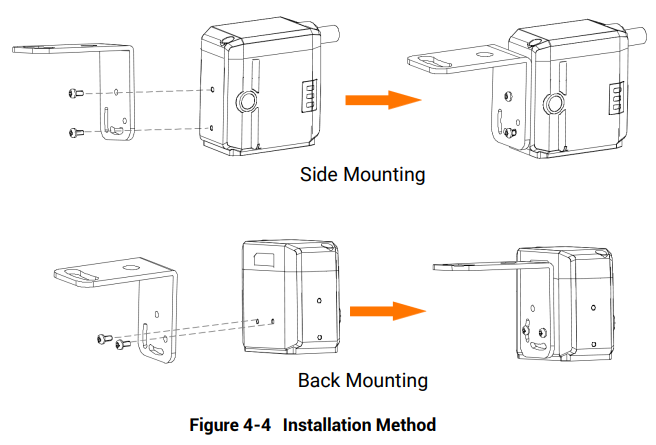
● Make sure that all related devices are powered off during the installation. You can use L-type bracket to install the device. Side mounting or back mounting is supported.

Steps
1. Use two M3 screws to fix the L-type bracket or other structural part to the mounting hole on the side or back of the device.
2. Fix the device to the mechanical assembly via the L-type bracket or other structural part.
No comments to display
No comments to display