
5. I/O Electrical Features and Wiring
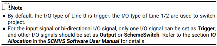
The device has four I/O interfaces and one RS-232 serial port. The four I/O interfaces include one input signal (Line 2), one output signal (Line 3), and two bi-directional I/Os (Line 0/1) that can be configured as input or output.
5.1 Input Signal
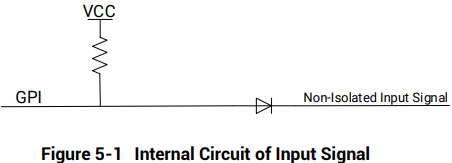
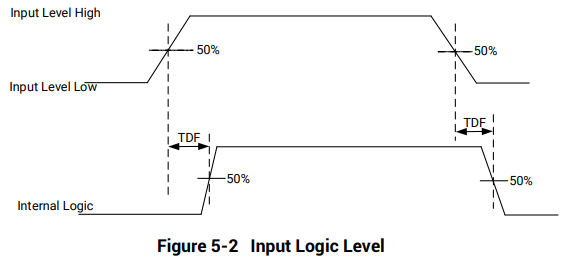
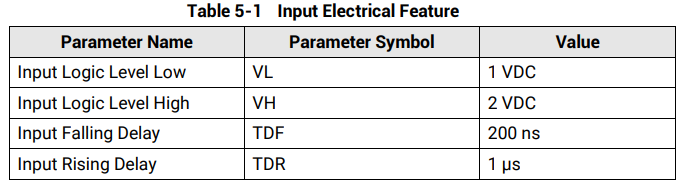
The device has one input signal (Line 2) and two bi-directional I/Os (Line 0/1) that can be configured as input signal, and their internal circuit is shown below.

5.2 Output Signal
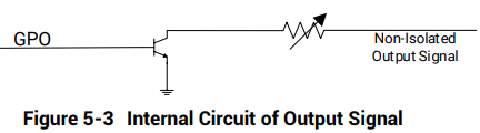
The device has one output signal (Line 3) and two bi-directional I/Os (Line 0/1) that can be configured as output signal, and their internal circuit is shown below.

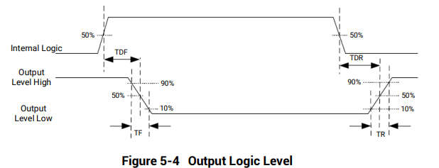
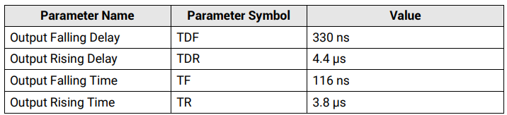
When the external voltage is 12 VDC and pull-up resistor is 1 KΩ, the output electric feature is shown below.

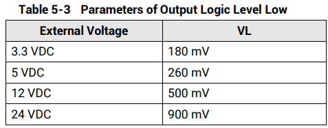
Relation between different external voltages and output logic level low is shown below.
5.3 I/O Wiring
The device can receive input signals from external devices and output signals to external devices. This section introduces how to wire the device’s I/O
Input/output signal wiring may differ by the type of the external device.
PNP Device
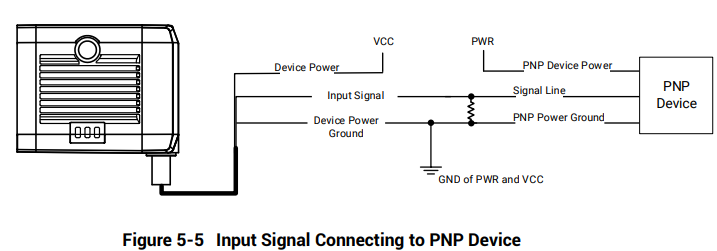
● When the bi-directional I/O is set as the non-isolated input signal for connecting to the PNP device, you should use a 1 KΩ pull-down resistor.
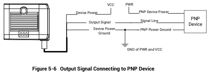
● When the bi-directional I/O is set as the non-isolated output signal for connecting to the PNP device, the wiring diagram is shown below.
NPN Device
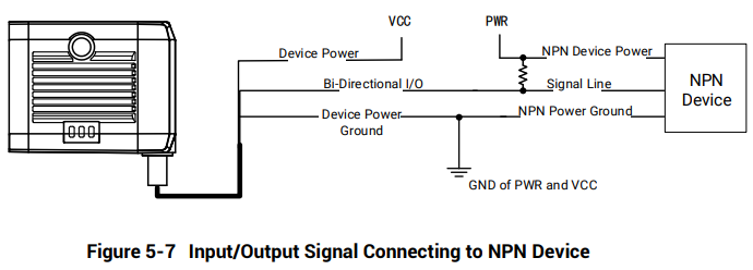
● When the bi-directional I/O is set as the non-isolated input/output signal for connecting to the NPN device, you should use a 1 KΩ pull-down resistor.
Switch
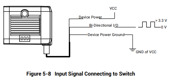
● When the bi-directional I/O is set as the non-isolated input signal for connecting to the switch, the wiring diagram is shown below.
5.4 RS-232 Serial Port
The device supports outputting data via RS-232 serial port, and you can set serial port communication via the client software. Refer to the SCMVS Software User Manual for details.
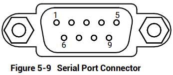
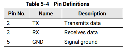
The supplied 17-pin cable has a 9-pin serial port connector. Refer to the figure and table below for pin definitions.
No comments to display
No comments to display