
2. DESCRIPTION AND OPERATION
This chapter provides an overview of how the Indexer 2 Program operates.
2.1: Operational Overview
On startup, the Indexer 2 Program zeros its program registers and enters its main loop, continually polling first the user defined Priority input (if configured) and then the user-defined Go input or register. Optionally, one sequence can be selected to execute on power up or amplifier reset.
If a Priority input or Go command is active, the Indexer 2 Program executes the selected sequence. The program puts the amplifier in the correct mode of operation to execute each step of the sequence as it progresses. During sequence execution, the Priority, Go, and sequence selection inputs are ignored. After successful completion of a sequence, the Indexer 2 Program returns to the main loop.
If an error occurs during a sequence, one of two responses can be programmed for each sequence:
The current sequence is aborted and the Indexer 2 Program reverts back to its main loop, or
The Indexer 2 Program starts immediate execution of another programmed sequence. At the end of this sequence, the program returns to its main loop.
2.2: Sequence Selection
The Indexer 2 Program can store up to 32 sequences (0 to 31). Upon receiving a Go command, the program executes the sequence that has been selected by a register or by digital inputs.
2.2.1: Use a Register to Select a Sequence
When the Indexer 2 Program receives a Go command and Use register to select sequence is the programmed sequence selection method, the program reads the first 5 bits (0-4) of the specified register to select a sequence. To select a sequence, write to the register a hex value (0x00 - 0x1f) or a decimal value (0 - 31). To write to a register using ASCII commands, see Reading and Writing Registers
2.2.2: Use Digital Inputs to Select a Sequence
Conflicting use of inputs is possible.

It is possible to assign functions to the inputs though the CME 2 Input/Output configuration screen that would conflict with the use of the BCD sequence selection, Priority and Go inputs assigned by Indexer 2 Program. Both functions of the input would be in effect simultaneously and might cause unexpected results. Exercise care to avoid such conflicts when assigning input functions.
Failure to heed this warning can cause equipment damage, injury, or death.
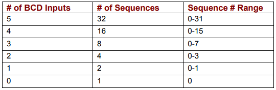
When the Indexer 2 Program receives a Go command and Use digital input is the programmed sequence selection method, the amplifier’s digital inputs select the sequence to execute. Up to five inputs can be used to represent a binary coded number with a decimal value between 0 and 31.
The table below shows the number of input-selectable sequences per number of inputs used.
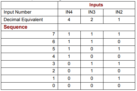
For instance, suppose the Indexer 2 Program has been configured to read three sequence selection inputs starting at IN2. This table shows the input states that would select each:
2.3: Go Command
A Go command causes Indexer 2 to execute the selected sequence. Programmable Go command trigger options include registers, digital inputs, and immediate single Go on startup or reset.
2.3.1: Use a Register to Initiate Go
When programmed to Use Register to Initiate Go, the Indexer 2 Program monitors bit 15 of the programmed Go register. If Bit 15 is set to 1 the program executes the selected sequence.
To initiate a register-driven Go when the sequence will be selected by digital inputs, set Bit 15 of the Go register by writing to the Go register a hex value 0x8000, or the decimal equivalent, 32768. (All other bits will be ignored.) To write to a register using ASCII commands, see Reading and Writing Registers.
When Go command and sequence selection are both programmed to Use Register, the same register is used for both purposes. In this case, use the same write operation to write the sequence to the register and set Bit 15 at the same time. For instance, to execute Sequence 12, write to the register the hex value 0x800c or the decimal equivalent, 32780.
Note that the Indexer 2 Program clears Bit 15 before executing the sequence so that a register or digital input cannot trigger another Go until Bit 15 is reset. (The state of Bit 15 does not affect the operation of Immediate Single Go.)
2.3.2: Use a Digital Input to Initiate Go
When programmed to Use Input to Initiate Go, the Indexer 2 Program monitors the state of the programmed Go input. The Go can be programmed to happen whenever the input is at the specified level (low or high), or only on the rising or falling edge of an input transition.
2.3.3: Use Immediate Single Go on Startup or Reset
This option programs the Indexer to trigger a Go command when the amplifier is powered up or reset or the Run button is pushed. A sequence is selected according to the programmed sequence selection choices.
If the Indexer is programmed to Use register to select sequence, then the sequence executed will be number 0, because all registers are cleared when the program starts.
If sequence selection is programmed to Use digital input, then the states of the programmed selection inputs determine which sequence is executed.
After immediate single Go, further Go commands are executed as programmed.
2.4: Summary: Sequence Selection and Go Choices
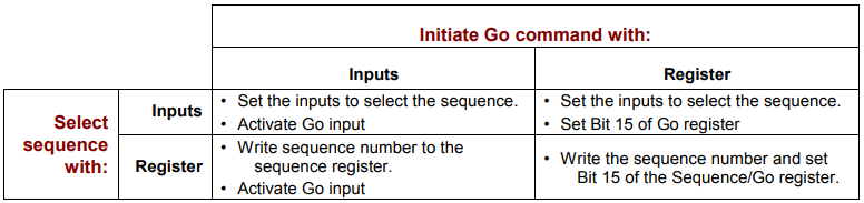
Either of the sequence selection methods (register or input) can be used with either of the Go initiation methods (register or input) in any combination, as shown below.
2.5: Priority Input Command
In addition to the 32 normal sequences, the Indexer 2 Program supports a Priority sequence. Unlike other sequences, the Priority sequence:
is selected and initiated with a single digital input
receives process priority over other sequence selection methods
Note that a Priority sequence does not stop or override any sequence in progress.
2.6: Indexer 2 Program Registers
The Indexer 2 Program has 32 registers that can be used to select sequences, initiate Go commands, and pass numeric parameters to functions in sequence steps. Each register is 32 bits long.
Register references can be used to pass numeric parameters, such as gains and trajectory settings, to most Indexer 2 Program functions. A register reference takes the form Rn, where n is a register number (0-31). For more details see Using Registers to Pass Values to Functions.
Control applications (HMI, PLC, or PC-based programs) can use any of the supported protocols to read and write the Indexer 2 Program registers. Supported protocols include the Copley ASCII Interface, CANopen, and DeviceNet.
For experimentation and simple setup and control, the CME 2 ToolsASCII Command Line feature can also be used, as can a telnet device such as the standard Microsoft Windows HyperTerminal. See ASCII Commands Over Serial.
Current register values can also be viewed while the Indexer 2 Program is running by using the CME 2 CVM Control Program ViewRegister Values command.
NOTE: Starting the Indexer 2 Program always sets all register values to zero.
2.7: Diagram of Typical Connections
In a typical Indexer 2 Program application, the connections between a Copley Controls amplifier and a PLC resemble those shown below.
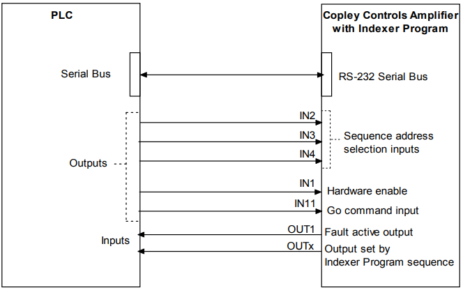
Here, inputs IN2-IN4 are used for sequence selection. Input IN11 is programmed to initiate the Indexer 2 Program Go command. The amplifier’s hardware enable input, IN1, is also controlled by the PLC. OUT1 is configured to go active when an amplifier fault occurs, and any of the amplifier’s digital outputs can be set by a step in an Indexer 2 Program sequence. The serial connection can be used to set register values.
No comments to display
No comments to display