
APPENDIX B: HOMING METHOD DESCRIPTIONS
This appendix describes the homing methods that can be chosen using the Indexer 2 Program
Home function
B.1: Homing Methods Overview
There are several homing methods. Each method establishes the:
Home reference (limit or home switch transition or encoder index pulse)
Direction of motion and, where appropriate, the relationship of the index pulse to limit or home switches.
B.2: Legend to Homing Method Descriptions
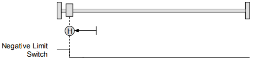
As highlighted in the example below, each homing method diagram shows the starting position on a mechanical stage. The arrow line indicates direction of motion, and the circled H indicates the home position. Solid line stems on the index pulse line indicate index pulse locations. Longer dashed lines overlay these stems as a visual aid. Finally, the relevant limit switch is represented, showing the active and inactive zones and transition.
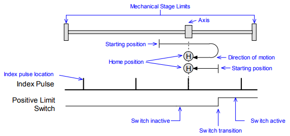
Note that in the homing method descriptions, negative motion is leftward and positive motion is rightward.
B.3: Homing Method Descriptions
B.3.1: Set current position as home
The current position is the home position.
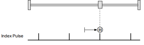
B.3.2: Next Index
Direction of Motion: Positive
Home is the first index pulse found in the positive direction. Direction of motion is positive. If a positive limit switch is activated before the index pulse, an error is generated.
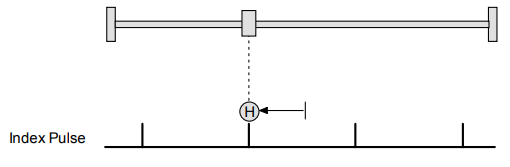
Direction of Motion: Negative
Home is the first index pulse found in negative direction. Direction of motion is negative. If a negative limit switch is activated before the index pulse, an error is generated.
B.3.3: Limit Switch
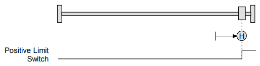
Direction of Motion: Positive
Home is the transition of the positive limit switch. Initial direction of motion is positive if the positive limit switch is inactive.
Direction of Motion: Negative
Home is the transition of negative limit switch. Initial direction of motion is negative if the negative limit switch is inactive.
B.3.4: Limit Switch Out to Index
Direction of Motion: Positive
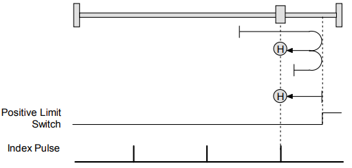
Home is the first index pulse to the negative side of the positive limit switch transition. Initial direction of motion is positive if the positive limit switch is inactive (shown here as low).
Direction of Motion: Negative
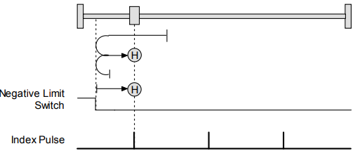
Home is the first index pulse to the positive side of the negative limit switch transition. Initial direction of motion is negative if the negative limit switch is inactive (shown here as low).
B.3.5: Hardstop
Direction of Motion: Positive
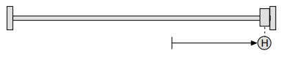
Home is the positive hard stop. Direction of motion is positive. The hard stop is reached when the amplifier outputs the homing Current Limit continuously for the amount of time specified in the Delay Time. If a positive limit switch is activated before the hard stop, an error is generated.
Direction of Motion: Negative
Home is the negative hard stop. Direction of motion is negative. The hard stop is reached when the amplifier outputs the homing Current Limit continuously for the amount of time specified in the Delay Time. If a negative limit switch is activated before the hard stop, an error is generated.

Hardstop Methods in Stepper Mode
In Stepnet amplifiers operating in stepper mode with an encoder, the hard stop is reached when the following error is exceeded. When using hardstop methods in stepper mode, do not disable following error.
B.3.6: Hardstop Out to Index
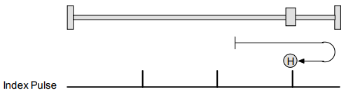
Direction of Motion: Positive
Home is the first index pulse on the negative side of the positive hard stop. Initial direction of motion is positive. The hard stop is reached when the amplifier outputs the homing Current Limit continuously for the amount of time specified in the Delay Time. If a positive limit switch is activated before the hard stop, an error is generated.
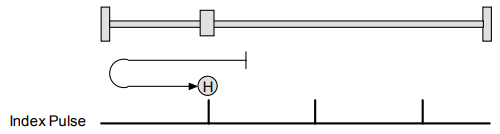
Direction of Motion: Negative
Home is the first index pulse on the positive side of the negative hard stop. Initial direction of motion is negative. The hard stop is reached when the amplifier outputs the homing Current Limit continuously for the amount of time specified in the Delay Time. If a negative limit switch is activated before the hard stop, an error is generated.
Hardstop Methods in Stepper Mode
In Stepnet amplifiers operating in stepper mode with an encoder, the hard stop is reached when the following error is exceeded. When using hardstop methods in stepper mode, do not disable following error.
B.3.7: Home Switch
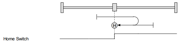
Direction of Motion: Positive
Home is the home switch transition. Initial direction of motion is positive if the home switch is inactive. If a limit switch is activated before the home switch transition, an error is generated.
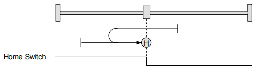
Direction of Motion: Negative
Home is the home switch transition. Initial direction of motion is negative if the home switch is inactive. If a limit switch is activated before the home switch transition, an error is generated.
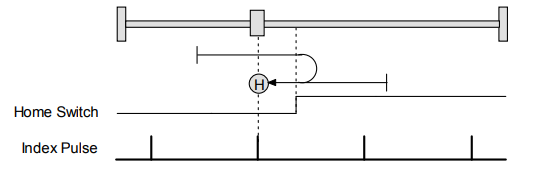
B.3.8: Home Switch Out to Index
Direction of Motion: Positive
Home is the first index pulse to the negative side of the home switch transition. Initial direction of motion is positive if the home switch is inactive. If a limit switch is activated before the home switch transition, an error is generated.
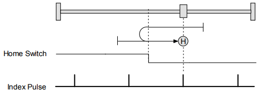
Direction of Motion: Negative
Home is the first index pulse to the positive side of the home switch transition. Initial direction of motion is negative if the home switch is inactive. If a limit switch is activated before the home switch transition, an error is generated.
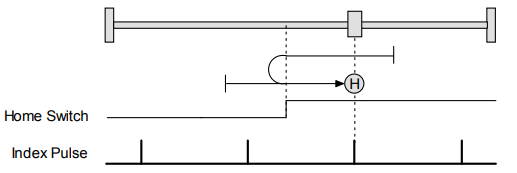
B.3.9: Home Switch In to Index
Direction of Motion: Positive
Home is the first index pulse to the positive side of the home switch transition. Initial direction of motion is positive if the home switch is inactive. If a limit switch is activated before the home switch transition, an error is generated.
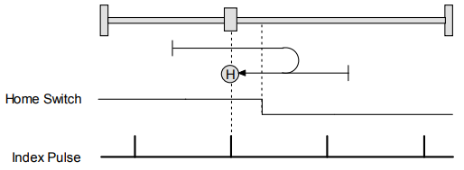
Direction of Motion: Negative
Home is the first index pulse to the negative side of the home switch transition. Initial direction of motion is negative if the home switch is inactive. If a limit switch is activated before the home switch transition, an error is generated.
B.3.10: Lower Home
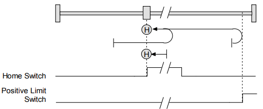
Direction of Motion: Positive
Home is the negative edge of a momentary home switch. Initial direction of motion is positive if the home switch is inactive. Motion will reverse if a positive limit switch is activated before the home switch; then, if a negative limit switch is activated before the home switch, an error is generated.
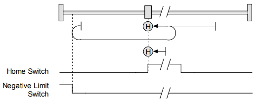
Direction of Motion: Negative
Home is the negative edge of a momentary home switch. Initial direction of motion is negative. If the initial motion leads away from the home switch, the axis reverses on encountering the negative limit switch; then, if a positive limit switch is activated before the home switch, an error is generated.
B.3.11: Upper Home
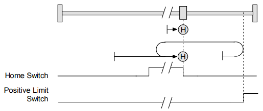
Direction of Motion: Positive
Home is the positive edge of a momentary home switch. Initial direction of motion is positive. If the initial motion leads away from the home switch, the axis reverses on encountering the positive limit switch; then, if a negative limit switch is activated before the home switch, an error is generated.
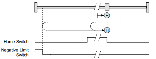
Direction of Motion: Negative
Home is the positive edge of momentary home switch. Initial direction of motion is negative if the home switch is inactive. If the initial motion leads away from the home switch, the axis reverses on encountering the negative limit switch; then, if a positive limit switch is activated before the home switch, an error is generated
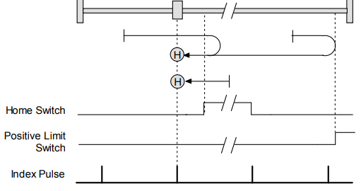
B.3.12: Lower Home Outside Index
Direction of Motion: Positive
Home is the first index pulse on the negative side of the negative edge of a momentary home switch. Initial direction of motion is positive if the home switch is inactive. If the initial motion leads away from the home switch, the axis reverses on encountering the positive limit switch; then, if a negative limit switch is activated before the home switch, an error is generated.
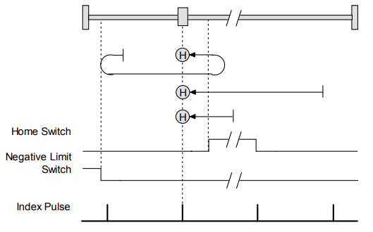
Direction of Motion: Negative
Home is the first index pulse on the negative side of the negative edge of a momentary home switch. Initial direction of motion is negative. If the initial motion leads away from the home switch, the axis reverses on encountering the negative limit switch; then, if a negative limit switch is activated before the home switch, an error is generated.
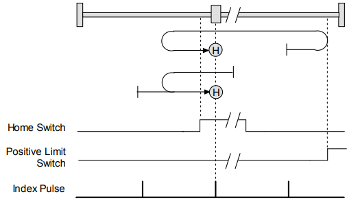
B.3.13: Lower Home Inside Index
Direction of Motion: Positive
Home is the first index pulse on the positive side of the negative edge of a momentary home switch. Initial direction of motion is positive if the home switch is inactive. If the initial motion leads away from the home switch, the axis reverses on encountering the positive limit switch; then, if a negative limit switch is activated before the home switch, an error is generated.
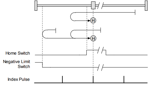
Direction of Motion: Negative
Home is the first index pulse on the positive side of the negative edge of a momentary home switch. Initial direction of motion is negative. If the initial motion leads away from the home switch, the axis reverses on encountering the negative limit switch; then, if a negative limit switch is activated before the home switch, an error is generated.
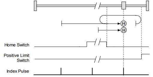
B.3.14: Upper Home Outside Index
Direction of Motion: Positive
Home is the first index pulse on the positive side of the positive edge of a momentary home switch. Initial direction of motion is positive. If the initial motion leads away from the home switch, the axis reverses on encountering the positive limit switch; then, if a negative limit switch is activated before the home switch, an error is generated.
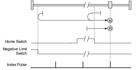
Direction of Motion: Negative
Home is the first index pulse on the positive side of the positive edge of a momentary home switch. Initial direction of motion is negative if the home switch is inactive. If the initial position is right of the home position, the axis reverses on encountering the home switch.
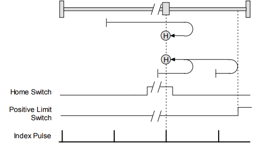
B.3.15: Upper Home Inside Index
Direction of Motion: Positive
Home is the first index pulse on the negative side of the positive edge of momentary home switch. Initial direction of motion is positive. If initial motion leads away from the home switch, the axis reverses on encountering the positive limit switch; then, if a negative limit switch is activated before the home switch, an error is generated.
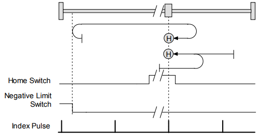
Direction of Motion: Negative
Home is the first index pulse on the negative side of the positive edge of a momentary home switch. Initial direction of motion is negative if the home switch is inactive. If initial motion leads away from the home switch, the axis reverses on encountering the negative limit; then, if a negative limit switch is activated before the home switch, an error is generated.
No comments to display
No comments to display