
3. FUNDAMENTAL CONCEPTS AND PROCEDURES
Before exploring any of the Copley Motion Objects sample programs or developing a new program, the programmer should be familiar with the contents of this chapter.
3.1: Before Running a Copley Motion Objects Program
The following general steps must be completed before running any Copley Motion Objects program, including the demonstration programs described in this manual:
3.1.1.1 Review the Product Warnings at the beginning of this manual (p. ii).
3.1.1.2 Install Copley Motion Objects as described in Installation (p. 5).
3.1.1.3 Install the CAN interface card’s driver and hardware. See the CAN card manufacturer’s documentation for more details.
3.1.1.4 Connect the amplifier, motor, and CAN network.
3.1.1.5 Set up and tune the motor and amplifier using Copley Controls CME 2 software. Be sure to set the CAN address and bit rate as described in CAN Network (p. 9)
3.2: CAN Network
3.2.1: Addressing and Bit Rate
Use Copley Controls CME 2 software to set up the amplifier’s CAN address and bit rate. Setting the CAN address to 0 on an amplifier disables the CAN operation for that amplifier.
In accordance with the CAN DS-102 V2.0 Copley supports bit rates of 1,000, 800, 500, 250, 125, 50, and 20 kb/s.
For more information on changing the CAN address and bit rate settings, see the CME 2 User Guide. Manuals are available for download under the Documents heading at http://www.copleycontrols.com/motion/downloads.
3.2.2: CAN Communication and Connection Errors
Possible CAN communication and connection errors include:
• The CAN address is incorrect
• The bit rate is incorrect
• The wrong CAN channel is connected on a multiple-channel CAN card.
• The CAN bus is improperly terminated.
• CAN bus is wired improperly or disconnected.
If any of these errors occurs, the Copley Motion Object typically responds with the error "SDO Timeout," indicating that there was an attempt to transmit a CANopen SDO information packet, but the packet reception was not confirmed.
3.3: Adding a Reference to a Program
For a program to use the Copley Motion Objects, a reference must first be added. Below are examples of adding a reference to the Copley Motion Objects in various environments.
3.3.1: Adding a Reference to a Program in VB
3.3.1.1 In the project workspace menu, choose the add reference command.
For instance, in .NET 2005: ProjectAdd Reference to open the Add Reference window, then select the COM tab.

3.3.1.2 Scroll to highlight the entry for CMO Type Library.
3.3.1.3 Click OK.
3.3.2: Adding a Reference to a Program in LabVIEW:
3.3.2.1 From the Refnum controls, choose Automation Refnum.
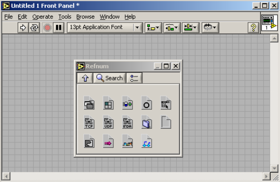
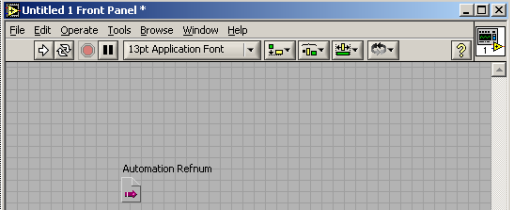
3.3.2.2 Place the Automation Refnum on the Front Panel.
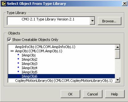
3.3.2.3 Right-click on the Automation Refnum block and choose Select ActiveX Class. Then browse to the CMO object in the Type Library list. Check Show Creatable Objects Only and then select the desired CMO object.
3.4: Object Initialization Sequence
3.4.1: CAN Network, and Amplifier Objects
Every Copley Motion Objects application requires the creation and initialization of at least two basic objects: one to represent the network, and one to represent each amplifier. These objects should always be initialized in the following order:
1. CANopen network object: CANOpenObj. See the CANOpenObj method Initialize.
2. Amplifier objects: AmpObj. See the AmpObj method Initialize. Failure to follow this sequence will result in an error.
3.5: Objects Contained by AmpObj
3.5.1: Overview
In addition to numerous methods and properties, the amplifier object is made up of several other objects. These are:
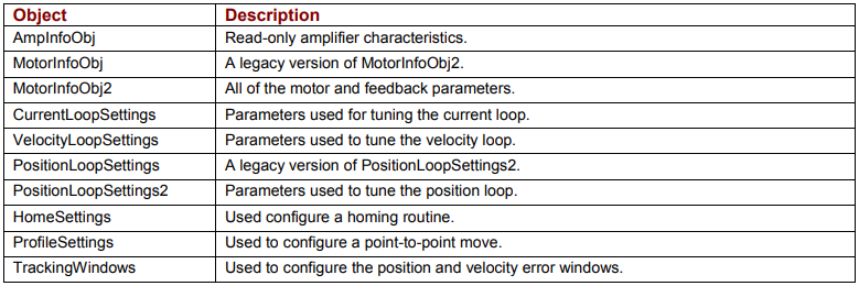
Each of these objects has a set of related methods and properties.
3.5.2: Creating and Initializing Objects Contained by AmpObj
The following examples use the ProfileSettings object to demonstrate the basic methods for using any of the objects contained in the AmpObj.
The AmpObj must first be Initialized before accessing the objects as properties. (See Initialize .)
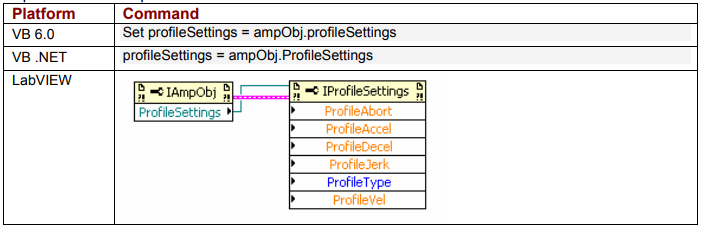
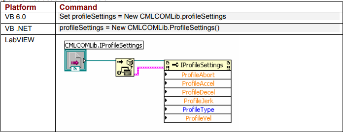
There are two ways to create an instance of the ProfileSettings object:
3.5.2.1 Get the instance from the AmpObj. This is the preferred method, because it sets all of the properties of the ProfileSettings object equal to the values programmed in the amplifier. Platform-specific instructions shown below.
 3.5.2.2 Create a new instance. This sets default values for all of the properties. Platformspecific instructions shown below.
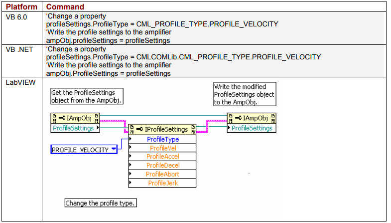
3.5.3: Modifying an AmpObj Object
Once an instance of the ProfileSettings object has been created as described in Creating and Initializing Objects Contained by AmpObj (p. 13), any of the properties can be changed and written back to the amplifier. See the platform-specific instructions below.
3.6: Node Guarding
3.6.1: Node Guarding Overview
Node guarding is a CANopen device-monitoring feature. The network manager configures the amplifier to expect node-guarding messages at some interval. The network manager then sends a message to the amplifier at that frequency, and the amplifier responds with a node-guarding message. This allows both the network manager and the amplifier to identify a network failure if the guarding messages stop. CMO can turn node guarding on or off, and change the interval. If the amplifier detects that the guarding messages stop, it will abort a move in progress and set the AMPEVENT_NODEGUARD bit active in the Amplifier Event Register. If node guarding is turned on, we recommend monitoring amplifier events for the node guard event. This can be done through the EventObj (see D: The Event Object) or through a timer, which periodically reads the event mask. See Node Guarding.
3.6.2: Possibility of False Node Guarding Conditions
In a Windows environment, various factors can delay node-guarding messages, resulting in “false” node guarding conditions. These factors include the non-deterministic nature of Windows operating systems and the performance effects of other processes running on the PC. Thus, by default, node guarding is disabled in Copley Motion Objects. If node guarding is required, do note enable node guarding without first testing the performance characteristics and usage load of the PC being used, and adjusting the node guarding parameters accordingly using the AmpSettingsObj Methods and Properties.
3.7: Error Handling
Copley Motion Objects test for error conditions. If an error is present, Copley Motion Objects reports the error in the form of COM-compatible error objects. The error object includes a text description, error number, and the source of the error. For better error handling, each program should include error-handling procedures to guarantee that unexpected motion does not occur.
3.8: Units
3.8.1: Default Amplifier Units
The default Copley Motion Objects units are encoder counts.
• Position or Distance: encoder counts
• Velocity: 0.1 encoder counts per second
• Acceleration: 10 encoder counts per second2
• Deceleration: 10 encoder counts per second2
• Jerk: 100 encoder counts per second3
3.8.2: User-Defined Units
The Amplifier Object property CountsPerUnit can store a scaling factor for converting between an amplifier’s default units (encoder counts) and user-defined units. Default = 1. For example, with a 5-miron encoder on a linear motor, to program in millimeters, set CountsPerUnit = 200, since there are 200 encoder counts in one millimeter.
3.9: Stepnet Amplifiers
3.9.1: Stepper and Servo Modes
On power up/reset Stepnet amplifiers start in stepper mode. If it is necessary to switch a Stepnet amplifier from step to servo mode, set the property AmpMode (p. 49) to one of the servo modes listed in Modes of Operation for CML_AMP_MODE (p. 50). This should be done immediately after amplifier initialization.
In the following example, the amplifier is initialized and then the amplifier’s mode of operation is switched to the servo Can profile mode:
ampObj.Initialize(canOpen, 1)
ampObj.AmpModeWrite = CMLCOMLib.CML_AMP_MODE.AMPMODE_SERVO_CAN_PROFILE
3.9.2: Open Loop Stepper Mode Actual Position and Velocity
When running open loop stepper mode, actual position and actual velocity readings remain at zero. The motor’s commanded position can be monitored with CMLCOMLib.AmpObj.PositionCommand (Units: microsteps).
The motor’s commanded velocity can be monitored with CMLCOMLib AmpObj.TrajectoryVel (Units microsteps/second).
When the amplifier is disabled, PositionCommand goes to zero because the amplifier cannot tell if the motor moves while disabled. As long as the amplifier is enabled, relative and absolute moves can be made based on PositionCommand.
3.9.3: Stepper Mode with Encoder Actual Position and Velocity
When running in stepper mode with an encoder, actual position can be monitored with CMLCOMLib.AmpObj.PositionActual (Units: microsteps). Actual velocity can be monitored with CMLCOMLib.AmpObj.VelocityLoad (Units microsteps/second).
NOTE: Actual velocity can also be monitored with CMLCOMLib.AmpObj.VelocityActual, but the units will be in encoder counts/second. This is not recommended, because user units will also be applied to this value.
No comments to display
No comments to display