
2. Variable Data Types
Different types of variables are supported by different domains, which are detailed as follows:
System Domain: The system predefined variables, which cannot be edited.
Global Domain: IO data type, PLC data type, socket data type, position data types, area data type, basic data type, weave data type, clock data type, pallet data type, and system data type.
Project Domain: IO data type, socket data type, position data types, basic data type, weave data type, pallet data type, and system data type.
Program Domain: IO data type, socket data type, position data type, basic data type, and system data type.
2.1 Basic data types
BOOL
This variable is used to store bool type data. It supports operations such as Create, Delete, and Modify in the scope of the three major variables: Global, Project, and Program.
Parameter description:
value: Data type: bool
Meaning: Variable value
saveflag: Data type: bool
Meaning: Power-down memory
INT
This variable is used to store integers. It supports operations such as Create, Delete, and Modify in the scope of the three major variables: Global, Project, and Program.
Parameter description:
value: Data type: int
Meaning: Variable value
saveflag: Data type: bool
Meaning: Power-down memory
REAL
This variable is used to store real numbers. It supports operations such as Create, Delete, and Modify in the scope of the three major variables: Global, Project, and Program.
Parameter description:
value: Data type: real
Meaning: Variable value
saveflag: Data type: bool
Meaning: Power-down memory
STRING
This variable is used to store character strings. It supports operations such as Create, Delete, and Modify in the scope of the three major variables: Global, Project, and Program.
Parameter description:
value: Data type: string
Meaning: Variable value
saveflag: Data type: bool
Meaning: Power-down memory
BoolOneArray
This variable is used to store bool type array data. It supports operations such as Create, Delete, and Modify in the scope of the three major variables: Global, Project, and Program.
Parameter description:
count: Data type: int
Meaning: Count of data
value: Data type: bool
Meaning: Variable value
IntOneArray
This variable is used to store the integer array data. It supports operations such as Create, Delete, and Modify in the scope of the three major variables: Global, Project, and Program.
Parameter description:
count: Data type: int
Meaning: Count of data
value: Data type: int
Meaning: Variable value
RealOneArray
This variable is used to store the real array data. It supports operations such as Create, Delete, and Modify in the scope of the three major variables: Global, Project, and Program.
Parameter description:
count: Data type: int
Meaning: Count of data
value: Data type: real
Meaning: Variable value
2.2 Position data type
APOS
This variable is used to store the coordinate values of axis in the joint space. It supports users to create and modify independently, and to perform assignment operations and other jobs in the teaching program.
Also, it supports operations such as Create, Delete, and Modify in the scope of the three major variables: Global, Project, and Program.
Parameter description:
a1: Data type: real
Meaning: The coordinates of the 1# axis of the joint.
a2: Data type: real
Meaning: The coordinates of the 2# axis of the joint.
a3: Data type: real
Meaning: The coordinates of the 3# axis of the joint.
...: The attributes of the parameters a4~a15 are the same as above, they are Real type variables, representing in turn the coordinate values of the axes of joints 4~15.
a16: Data type: real
Meaning: The coordinates of the 16# axis of the joint.
[Note] The number of parameters of axes will be displayed based on the number of axes. For example, the general six-axis robot displays aa1~a6, while the scara robot displays a1~a4.
POSCFG
Robot may have differed joint position combinations under the same Cartesian space position (corresponding to the multiple solutions of the robot inverse solution). This attribute is used to define the morphological configuration data corresponded to the spatial target point.
Parameter description:
mode: Data type: int
cf1: Data type: int
Meaning: The value of quadrant where the angle of the1 # axis of the joint is located.
cf2: Data type: int
Meaning: The value of quadrant where the angle of the 2# axis of the joint is located.
cf3: Data type: int
Meaning: The value of quadrant where the angle of the 3# axis of the joint is located.
cf4: Data type: int
Meaning: The value of quadrant where the angle of the 4# axis of the joint is located.
cf5: Data type: int
Meaning: The value of quadrant where the angle of the 5# axis of the joint is located.
cf6: Data type: int
Meaning: The value of quadrant where the angle of the 6# axis of the joint is located.
The values of these quadrants are divided as follows:
Non-negative numbers: 0: (-pi,pi], 1: (pi,3pi], 2: (3pi,5pi], ...; 2pi difference between each quadrant
Negative numbers: -1: (-3pi,-pi], -2: (-5pi,-3pi], ...; -2pi difference between each quadrant
① Definition of general-purpose six-joint dynamics mode
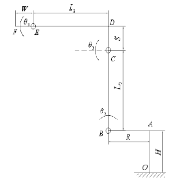
There are eight sets of solutions for the dynamics of the general-purpose six-joint. The mode value is defined as 0~7. The meanings are listed in table below:
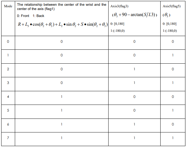
mode = flag5 + 2*flag3 + 4*flag1.
Notes:
aa. The relationship between the wrist center and the center of the axis is shown in the figure below. Front: refers to the positive direction of x in the figure; Back: refers to the negative direction of x in the figure.
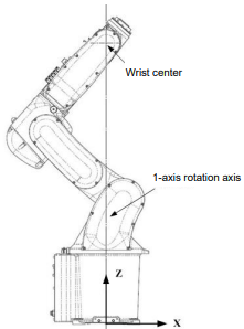
Meaning of bb: Axis3 (flag3): The second and third axis are on a straight line are taken as the boundary condition. 0 is for forward inclination, and 1 is for backward inclination.
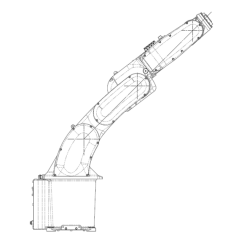
Meaning of cc: Axis5(flag5): The angle of 5 axes.
② Definition of SCARA dynamics mode
There are two sets of solutions for Scara dynamics. The mode values are defined as 0 and 1, with the meanings listed as follows:
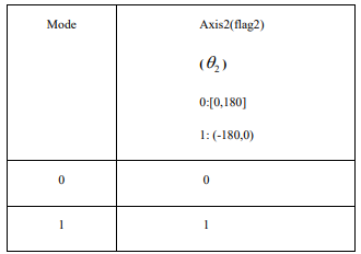
mode = flag2.
③ Definition of 3-axis plane robot dynamics + "3+1" robot mode
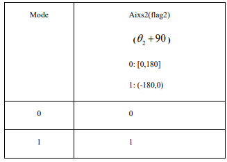
mode = flag2.
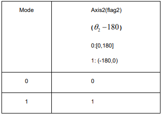
④ Definition of SCARA hoisting dynamics mode
There’re two sets of solutions for Scara hoisting dynamics. The mode value is defined as 0 and 1, with the meanings listed below:
CPOS
This variable is used to store the position of the TCP point in the Cartesian coordinates. It supports users to create and modify independently, and to perform assignment operations and other jobs in the teaching program. It also supports operations such as Create, Delete, and Modify in the scope of the three major variables: Global, Project, and Program
Parameter description:
confdata: Data type: POSCFG
Meaning: The morphological configuration information corresponded to the space target point.
x: Data type: real
Meaning: The coordinates of TCP point in the x direction in reference coordinates.
y: Data type: real
Meaning: The coordinates of TCP point in the y direction in reference coordinates.
z: Data type: real
Meaning: The coordinates of TCP point in the z direction in reference coordinates.
a: Data type: real
Meaning: The Euler angle of the TCP point relative to the z-axis of the reference coordinates
b: Data type: real
Meaning: The Euler angle of the TCP point relative to the y′-axis of the reference coordinates
c: Data type: real
Meaning: The Euler angle of the TCP point relative to the x″-axis of the reference coordinates
a7: Data type: real
Meaning: The coordinates of the 7# axis of the joint.
...: The attributes of parameters a8~a15 are similar to those mentioned above. They are all real-type variables and represent the coordinate values of Joints 8 to 15, respectively.
a16: Data type: real
Meaning: The coordinates of the 16# axis of the joint.
[Note] The number of parameters of axes will be displayed based on the number of axes
DAPOS
This variable is used to store the relative offset of each axis in the joint space. It supports users to create and modify independently, and to perform assignment operations and other jobs in the teaching program.
It also supports operations such as Create, Delete, and Modify in the scope of the three major variables: Global, Project, and Program.
Parameter description:
da1: Data type: real
Meaning: The angle offset of the 1# axis of the joint.
da2: Data type: real
Meaning: The angle offset of the 2# axis of the joint.
da3: Data type: real
Meaning: The angle offset of the 3# axis of the joint.
...: The attributes of parameters da4~da15 are similar to those mentioned above. They are all real-type variables and represent the offset angles of Joints 4 to 15, respectively.
da16: Data type: real
Meaning: The angle offset of the 16# axis of the joint.
[Note] The number of parameters of axes will be displayed based on the number of axes.. For example, the six-axis robot displays d1~d6, while the scara robot displays d1~d4.
DCPOS
This variable is used to store the relative offset of the TCP point in the Cartesian coordinates. It supports users to create and modify independently, and to perform assignment operations and other jobs in the teaching program. It also supports operations such as Create, Delete, and Modify in the scope of the three major variables: Global, Project, and Program.
Parameter description:
dx: Data type: real
Meaning: The displacement offset of TCP point in the x direction on the reference coordinates.
dy: Data type: real
Meaning: The displacement offset of TCP point in the y direction on the reference coordinates.
dz: Data type: real
Meaning: The displacement offset of TCP point in the z direction on the reference coordinates.
da: Data type: real
Meaning: The Euler angle offset of TCP point relative to the z-axis of the reference coordinates.
db: Data type: real
Meaning: The Euler angle offset of TCP point relative to the y′-axis of the reference coordinates.
dc: Data type: real
Meaning: The Euler angle offset of TCP point relative to the x″-axis of the reference coordinates.
da7: Data type: real
Meaning: The angle offset of the 7# axis of the joint.
...: The attributes of parameters da8 to da15 are indeed similar to those mentioned earlier. They are real-type variables and represent the offset angles of Joints 8 to 15, respectively.
da16: Data type: real
Meaning: The angle offset of the 16# axis of the joint.
[Note] The number of parameters of axes will be displayed based on the number of axes.
APOSARRAY
To store the APOS point array data. You can create, delete, and modify this variable only within the Global variable scope.
Parameter description:
count: Data type: int
Meaning: Count of data
APOSARRAY[X]: Data type: APOS
Meaning: The stored individual APOS values.
Note: [X] represents the index number of the array, such as APOSARRAY[0], APOSARRAY[1].
CPOSARRAY
To store the CPOS point array data. You can create, delete, and modify this variable only within the Global variable scope.
Parameter description:
count: Data type: int
Meaning: Count of data
CPOSARRAY[X]: Data type: CPOS
Meaning: The stored individual CPOS values.
Note: [X] represents the index number of the array, such as CPOSARRAY[0], CPOSARRAY[1].
2.3 System data type
CenterPos
The center of mass vector is set based on the position of the installed tool or load on the coordinates OToolXYZ, which his described below.
The direction of the tool & load mass information reference coordinates is shown in Figure 1 Figure 2 shows the definition example of the tool & load mass information coordinates.
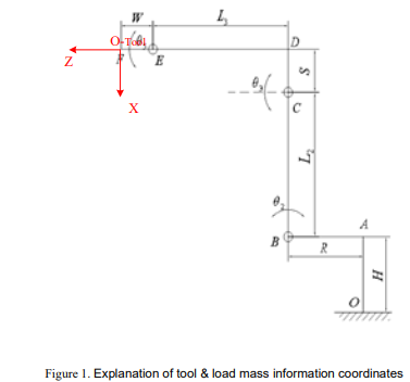
Note: The coordinate system OTool-XYZ is located at the end flange plane of the robot, and the Z axis of the coordinate system is coaxial with the axis of the J6 joint (taking 6-axis robot as an example).
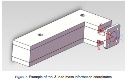
Note: Please refer to the coordinates OTool-XYZ in Figure 5-1 for the mass information output coordinates of tools and loads.
Parameter description:
Mx: Data type: real
Meaning: The offset of the load of the installed tool or fixture in the X direction in coordinates OToolXYZ, in mm. My: Data type: real
Meaning: The offset of the load of the installed tool or fixture in the Y direction in coordinates OToolXYZ, in mm. Mz: Data type: real
Meaning: The offset of the load of the installed tool or fixture in the Z direction in coordinates OToolXYZ, in mm.
InertiaTensor
This parameter represents the inertia tensor determined at the center position of the installed tool or payload. For a specific coordinate system diagram, you can refer to the explanatory diagram in the "CenterPos" variable type mentioned above.
Parameter description:
Ixx: Data type: real
Meaning: The moment of inertia when the load of the installed tool or fixture rotates in the X direction at the center of gravity, in kg·mm2.
Iyy: Data type: real
Meaning: The moment of inertia when the load of the installed tool or fixture rotates in the Y direction at the center of gravity, in kg·mm2
Izz: Data type: real
Meaning: The moment of inertia when the load of the installed tool or fixture rotates in the Z direction at the center of gravity, in kg·mm2.
Ixy: Data type: real
Meaning: The product of inertia of the load of the installed tool or fixture in the XY cross direction at the center of gravity, in kg·mm2.
Ixz: Data type: real
Meaning: The product of inertia of the load of the installed tool or fixture in the XZ cross direction at the center of gravity, in kg·mm2
Iyz: Data type: real
Meaning: The product of inertia of the load of the installed tool or fixture in the YZ cross direction at the center of gravity, in kg·mm2.
LoadDyn
It is used to store the end tool & load mass parameters of robot, and to calculate the full model of robot dynamics.
Parameter description:
M: Data type: real
Meaning: The weight of the tool & load, in kg.
pos: Data type: CenterPos
Meaning: See the meanings of CenterPos.
tensor: Data type: InertiaTensor
Meaning: See the meanings of InertiaTensor.
TOOL
The TOOL variable is used to record the tool parameters, and to define the displacement and rotation of the tool end in relation to the robot flange. The parameter can be calculated by the user based on the calibration of the variable interface or can be entered by the user. This variable can only be created and
modified in the Global domain.
Parameter description:
id: Data type: int
Meaning: The unique index number of tool coordinates. The value cannot be modified. It is assigned
automatically by the system when being created.
x: Data type: real
Meaning: The displacement offset of TCP relative to the flange coordinates in the x direction, in mm.
y: Data type: real
Meaning: The displacement offset of TCP relative to the flange coordinates in the y direction, in mm.
z: Data type: real
Meaning: The displacement offset of TCP relative to the flange coordinates in the z direction, in mm.
a: Data type: real
Meaning: The Euler angle of TCP relative to the z-axis of the flange coordinates, in deg.
b: Data type: real
Meaning: The Euler angle of TCP relative to the y′-axis of the flange coordinates, in deg.
c: Data type: real
Meaning: The Euler angle of TCP relative to the x″-axis of the flange coordinates, in deg.
dyn: Data type: LoadDyn
Meaning: The mass information of the tool, which is used to calculate the full model of robot dynamics.
The system predefines the tool variable nullTool, in which the value of each offset is 0 by default. User can define the tool coordinates to be used on the basis of site requirements.
USERCOOR
The USERCOOR variable type is used to record user coordinate system parameters, defining the displacement and rotation of the user coordinate system relative to the World (Base) Coordinate System. This parameter can be calculated based on calibration using the variable interface or input manually by the user. The creation and modification of this variable are only allowed within the Global domin.
Parameter description:
id: Data type: int
Meaning: The unique index number of the user coordinates. The value cannot be modified. It is assigned automatically by the system when being created.
x: Data type: real
Meaning: Displacement offset of TCP in the x-direction relative to the World (Base) Coordinate System, measured in mm.
y: Data type: real
Meaning: Displacement offset of TCP in the y-direction relative to the World (Base) Coordinate System, measured in mm.
z: Data type: real
Meaning: Displacement offset of TCP in the z-direction relative to the World (Base) Coordinate System, measured in mm.
a: Data type: real
Meaning: uler angle representing the rotation of TCP around the z-axis of the World (Base) Coordinate System, measured in degrees.
b: Data type: real
Meaning: Euler angle representing the rotation of TCP around the y -axis of the World (Base) Coordinate System, measured in degrees.
c: Data type: real
Meaning: Euler angle representing the rotation of TCP around the x -axis of the World (Base) Coordinate System, measured in degrees.
The system predefines the world coordinates World, in which the value of each offset is 0 by default.
User can define the user coordinates to be used on the basis of site requirements.
EXTTCP
EXTTCP variable is used to record the parameters of external tool coordinates, and to define the displacement and rotation of the external tool coordinates relative to the world coordinates. The parameter can be calculated based on the variable interface calibration, or be input by the user. This variable can only be created and modified in the Global domain.
Parameter description:
id: Data type: int
Meaning: The unique index number of the external tool coordinates. The value cannot be modified. It is assigned automatically by the system when being created.
x: Data type: real
Meaning: Displacement offset of TCP in the x-direction relative to the Tool Coordinate System, measured in mm.
y: Data type: real
POSITIONER
The POSITIONER type variable selects the positioner (ID) by index.
Parameter description:
index: Positioner serial number
Data type: int
Meaning: The range of index values is [0, 6]. In this context, 0 represents that the variable is invalid, while
SPEED
It is used to define the motion speed of the robot and the external axis. For easy use, the system presets the common speed variables (system variables, not to be modified by users). It also supports operations such as Create, Delete, and Modify in the scope of the three major variables Global, Project, and Program.
Parameter description:
per: The percentage of joint speed.
Data type: real
Meaning: It is used to specify the motion speed for joint motion commands. It is applicable to commands MovJ, MovJRel and MovJSearch, and the value ranged from 1% to 100%.
tcp: TCP line speed
Data type: real
Meaning: It is used to define the linear speed of the robot endpoint. It is used for MovL, MovC and other linear and full-circle motion commands.
ori: Spatial rotating speed
Data type: real
Meaning: It is used to define the rotation speed of the endpoint posture of the robot.
exj_l: The external axis linear speed.
Data type: real
Meaning: It is used to define the motion speed of the external linear axis.
exj_r: The angular speed of the external axis.
Data type: real
Meaning: It is used to define the motion speed of the external rotating axis.
ZONE
It is used to define how a motion ends, or to define the size of the turning area between two motion trajectories. For easy use, the system presets the commonly used transition variables (system variables, not to be modified by the user). It also supports operations such as Create, Delete, and Modify in the scope of the three major variables Global, Project, and Program.
Parameter description:
per: Joint path turn percentage:
Data type: real
Meaning: Applicable to joint motion commands such as MovJ, MovJRel, MovJSearch, etc. It represents the distance remaining to the target angle when the turn begins.
dis: The size of the turning area in Cartesian space.
Data type: real
Meaning: It is used in linear arc motion commands such asMovL, MovC, etc., to define the turning area size of the Cartesian space trajectory, that is, when the robot moves to a place that is still dis mm away from the target point, it starts to move to the next target point. It is in mm.
vConst: Constant speed transition enable state.
Data type: int
Meaning: The enable state indicating whether the linear speed of the transition section to be constant or not. 1 means the transition is constant, and 0 means the change in the tracking transition parameters.
Note: This parameter is typically used when the online speed is not high, and the specific value may vary depending on the robot type.
PAYLOAD
The PAYLOAD variable is used to record the workpiece load parameters, and to define the robot end-load parameters and mass information. The use of detailed mass information assists in the full model calculation of the robot dynamics in order to improve the motion tact even more. This parameter can currently only be entered by the user after calculating the value in advance, without a programming pendant calibration calculation. This variable can only be created and modified in the Global domain.
Parameter description:
id: Data type: int
Meaning: The unique index number of the workpiece load. The value cannot be modified. It is assigned automatically by the system when being created.
dyn: Data type: LoadDyn
Meaning: Mass information of workpiece loads for full model calculations of robot dynamics.
The system has a predefined workload of PAYLOAD0, where the default value for each offset is 0. The user may define the workpiece parameters to be used according to the site requirements.
LsScale
The LsScale variable is used to record the gain ratio threshold parameter for each joint axis to improve the low-speed jitter in a certain speed range and is used in conjunction with the speed range threshold parameter. This variable can only be created and modified in the Global domain.
Parameter description:
J1: Data type: int
Meaning: Gain ratio threshold corresponding to J1 axis, in %
J2: Data type: int
Meaning: Gain ratio threshold corresponding to J2 axis, in %
J3: Data type: int
Meaning: Gain ratio threshold corresponding to J3 axis, in %
J4: Data type: int
Meaning: Gain ratio threshold corresponding to J4 axis, in %
J5: Data type: int
Meaning: Gain ratio threshold corresponding to J5 axis, in %
J6: Data type: int
Meaning: Gain ratio threshold corresponding to J6 axis, in %
LsThresh
The LsThresh variable is used to record the speed interval threshold for each joint axis to improve low speed jitter in a certain speed interval and is used in conjunction with the gain ratio threshold parameter.
The range is [10,1000], in r/min. This variable can only be created and modified in the Global domain.
Parameter description:
J1: Data type: int
Meaning: Speed interval threshold corresponding to J1 axis, in %
J2: Data type: int
Meaning: Speed interval threshold corresponding to J2 axis, in %
J3: Data type: int
Meaning: Speed interval threshold corresponding to J3 axis, in %
J4: Data type: int
Meaning: Speed interval threshold corresponding to J4 axis, in %
J5: Data type: int
Meaning: Speed interval threshold corresponding to J5 axis, in %
J6: Data type: int
Meaning: Speed interval threshold corresponding to J6 axis, in %
INTERRUPT
This variable is used to store information about the INTERUPT name as a unique index of the interrupt identifier. It only supports It also supports operations such as Create, Delete, and Modify in the Global variable scope.
Parameter description:
value: Data type: string
Meaning: Store information on the name of the interrupt marker.
Note: When creating this variable on the teach pendant, the Variable value will automatically synchronize with the variable name. For example, if an INTERRUPT type variable named "Inq" is created, the Inq.value will also be "Inq" after creation.
COLLIPARAM
The COLLIPARAM variable is used to select the corresponding collision self-tuning parameter (ID) by means of an index.
Parameter description:
index: The Collision Auto Tune parameter index
Data type: int
Meaning: The range of values is [0, 6]. Where 0 means that the variable is invalid, and other means that the collision self-tuning parameter with ID index.
2.4 IOData type
DI
The digital input variable.
Parameter description:
port: Data type: int
Meaning: The digital input port number bound to such variable.
value: Data type: int
Meaning: The value is 0 or 1, indicating the input status of the corresponding port.
riseSts: Data type: bool
Meaning: The rising edge signal status of the port.
downSts: Data type: bool
Meaning: The falling edge status of the port.
DO
The digital output variable.
Parameter description:
port: Data type: int
Meaning: The digital output port number bound to such variable.
value: Data type: int
Meaning: The value is 0 or 1, indicating the output status of the corresponding port
AI
The analog input variable.
Parameter description:
port: Data type: int
Meaning: The analog input port number bound to such variable.
value: Data type: real
Meaning: Its value is ranged from -10 to 10V, indicating the input voltage value of the corresponding port.
AO
The analog output variable.
Parameter description:
port: Data type: int
Meaning: The analog output port number bound to such variable.
value: Data type: real
Meaning: Its value is ranged from -10 to 10V, indicating the output voltage value of the corresponding port.
SimDI
The virtual analog input variable.
Parameter description:
port: Data type: int
Meaning: The virtual analog input port number bound to such variable.
value: Data type: int
Meaning: The value is 0 or 1, indicating the input status of the corresponding port.
riseSts: Data type: bool
Meaning: The rising edge signal status of the port.
downSts: Data type: bool
Meaning: The falling edge status of the port.
SimDO
The virtual analog output variable.
Parameter description:
port: Data type: int
Meaning: The virtual digital output port number bound to such variable.
value: Data type: int
Meaning: The value is 0 or 1, indicating the output status of the corresponding port.
SimAI
The virtual analog input variable.
Parameter description:
port: Data type: int
Meaning: The virtual analog input port number bound to such variable.
value: Data type: real
Meaning: Indicates the input value of the corresponding port
SimAO
The virtual analog output variable.
Parameter description:
port: Data type: int
Meaning: The virtual analog output port number bound to such variable.
value: Data type: real
Meaning: Indicates the output value of the corresponding port.
2.5 Weave data type
WEAVE
This variable is used to store some configuration parameters when the robot weaves on a straight line/arc trajectory. Also, it allows users to Create, Delete, Modify and other operations in the three variable scopes Global, Project, and Program.
Parameter description:
Type: Data type: int
Meaning: Weave type of robot. It is a sine Weave when the value is 1, and is a triangular Weave when the value is 2.
Freq: Data type: real
Meaning: The frequency when the robot weaves, in Hz.
Amp_L: Data type: real
Meaning: The amplitude when the robot weaves left, in mm.
Amp_R: Data type: real
Meaning: The amplitude when the robot weaves right, in mm.
StopTime_L: Data type: int
Meaning: The time when robot stops at wave peak. It refers to the time in ms at which the weaving stops when it reaches the left amplitude.
StopTime_R: Data type: int
Meaning: The time when robot stops at wave trough. It refers to the time in ms at which the weaving stops when it reaches the right amplitude.
StopTime_C: Data type: int
Meaning: The time when robot stops at the middle. It refers to the time in ms at which the weaving stops when it reaches the middle position.
RotAngle_X: Data type: real
Meaning: The rotating angle of the weaving reference plane around the weaving direction. This parameter is used to determine the final weaving plane, in deg.
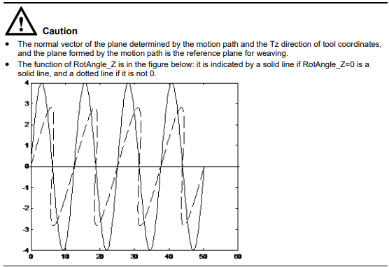
RotAngle_Z: Data type: real
Meaning: The rotating angle around the normal vector of the weaving plane, which determines the shape of the sine weave, in deg.
2.6 Clock data type
CLOCK
It is used to store the value of the clock information. It supports only the operations such as Create, Delete and Modify in the Global domin.
Parameter description:
id: Data type: int
Meaning: The number of the Clock variable.
state: Data type: real
Meaning: The enable state of the Clock variable.
value: Data type: real
Meaning: The count value of the Clock variable.
2.7 Area data type
AREA
It is used to store the value of Area information. It supports only the operations such as Create, Delete and Modify in the Global domin.
Parameter description:
id: Data type: int
Meaning: The number of local variables.
activate: Data type: bool
Meaning: Activate this area or not.
isInArea: Data type: bool
Meaning: Whether it is in this area.
initActivate: Data type: bool
Meaning: The AREA auto-activation flag.
areaType: Data type: int
Meaning: The type of area.
areaShape: Data type: int
Meaning: The shape of area.
refSysScope: Data type: int
Meaning: The scope of reference coordinates.
refSysName: Data type: string
Meaning: The name of the reference coordinates.
enInPut: Data type: bool
Meaning: Input enabling.
enInHigh: Data type: bool
Meaning: The input enabling is high and valid.
enOutPut: Data type: bool
Meaning: Output enabling.
enOutHigh: Data type: bool
Meaning: The output enabling is high and valid.
diType: Data type: int
Meaning: The type of DI.
InputActStatePort: Data type: int
Meaning: The actual input status.
doType: Data type: int
Meaning: The type of DO.
OutputActStatePort: Data type: int
Meaning: The actual output status.
StartPointX: Data type: real
Meaning: The coordinate x of the origin of the area.
StartPointY: Data type: real
Meaning: The coordinate y of the origin of the area.
StartPointZ: Data type: real
Meaning: The coordinate z of the origin of the area.
lenXR: Data type: real
Meaning: The length of the rectangular area, or the radius of the cylindrical area.
lenYH: Data type: real
Meaning: The width of the rectangular area, or the height of the cylindrical area.
lenZ: Data type: real
Meaning: The height of the rectangular area.
isFlangeEnd: Data type: int
Meaning: Used to monitor TCP or flange side in area monitoring
POLYHEDRON
The POLYHEDRON variable selects the polyhedron region (ID) by index. It supports only the operations such as Create, Delete and Modify in the Global domin.
Parameter description:
index: Data type: int
Meaning: The polyhedron area index. The index values range from 0 to 4. Here, 0 indicates that the variable is invalid, while other values represent the polyhedron area with the ID equal to the specified index.
activate: Data type: bool
Meaning: Whether this polyhedron area is active or not.
isInArea: Data type: bool
Meaning: Whether it is within the polyhedron area.
2.8 PLCData type
PLCREAL
It is used to store PLC real number, which correspond to real variables on the plc side according to the data number. It supports only the operations such as Create, Delete and Modify in the Global domin.
Parameter description:
plcNum: Data type: int
Meaning: Data number
value: Data type: real
Meaning: Variable value
saveflag: Data type: bool
Meaning: Power-down memory
PLCBOOL
It is used to store PLC boolean values, which correspond to bool variables on the plc side according to the data number. It supports only the operations such as Create, Delete and Modify in the Global domin.
Parameter description:
plcNum: Data type: int
Meaning: Data number
value: Data type: bool
Meaning: Variable value
saveflag: Data type: bool
Meaning: Power-down memory
PLCINT
It is used to store PLC short integer data according to the data number corresponding to the int variable on the PLC side. This variable only supports operations such as Create, Delete, and Modify in the global variable scope.
Parameter description:
plcNum: Data type: int
Meaning: Data number
value: Data type: int
Meaning: Variable value
saveflag: Data type: bool
Meaning: Power-down memory
PLCDINT
It is used to store PLC short integral values, which correspond to dint variables on the plc side according to the data number. It supports only the operations such as Create, Delete and Modify in the Global domin.
Parameter description:
plcNum: Data type: int
Meaning: Data number
value: Data type: int
Meaning: Variable value
saveflag: Data type: bool
Meaning: Power-down memory
2.9 Pallet data type
PLACEOPTIONS
The information contained in the pre-place and the post-place points in the Pallet variable. This data type can only be used together in a way being nested in the Pallet data type.
Parameter description:
isUse: Data type: bool
Meaning: Whether the parameter is valid or not.
sideOffset: Data type: real
Meaning: Horizontal offset.
height: Data type: real
Meaning: Height offset.
PALLET
It is used to store the Pallet information. This variable allows users to create and modify independently. It supports operations such as Create, Delete, and Modify in the scope of Global and Project variables.
Parameter description:
actParts: Data type: int
Meaning: The actual number of workpieces in the pallet.
maxParts: Data type: int
Meaning: The maximum number of workpieces in the pallet.
isEmpty: Data type: bool
Meaning: Pallet is empty or not.
isFull: Data type: bool
Meaning: Pallet is full or not.
xNum: Data type: int
Meaning: The number of workpieces in the x direction of the pallet.
yNum: Data type: int
Meaning: The number of workpieces in the y direction of the pallet.
zNum: Data type: int
Meaning: The number of workpieces in the z direction of the pallet.
xdistOfPart: Data type: real
Meaning: The length of a single workpiece in the x direction of the pallet.
ydistOfPart: Data type: real
Meaning: The length of a single workpiece in the y direction of the pallet.
zdistOfPart: Data type: real
Meaning: The length of a single workpiece in the z direction of the pallet.
refSysScope: Data type: int
Meaning: The scope of coordinates referred by the pallet parameters.
refSysName: Data type: string
Meaning: The name of coordinates referred by the pallet parameters.
palletDir: Data type: int
Meaning: The palletizing or de-palletizing direction.
palletOrder: Data type: int
Meaning: The palletizing or de-palletizing sequence.
firstPartScope: Data type: int
Meaning: The scope of the first workpiece position variable.
firstPartPos: Data type: string
Meaning: The name of the first workpiece position variable.
isEntryPosUsed: Data type: bool
Meaning: Move to the palletizing entry point or not.
palletEntryScope: Data type: int
Meaning: The scope of the palletizing entry point position variable.
palletEntryPos: Data type: string
Meaning: The name of the palletizing entry point position.
preplaceOptions: Data type: PLACEOPTIONS
Meaning: The pre-place information.
postplaceOptions: Data type: PLACEOPTIONS
Meaning: The post-place information.
2.10 SOCKET data type
Socket
It is used to store Socket name information. This variable allows users to create and modify independently.
It supports operations such as Create, Delete, and Modify in the scope of Global, Project and Program variables.
Parameter description:
value: Data type: string
Meaning: The name of socket.
No comments to display
No comments to display