
3. Commands
3.1 Motion commands
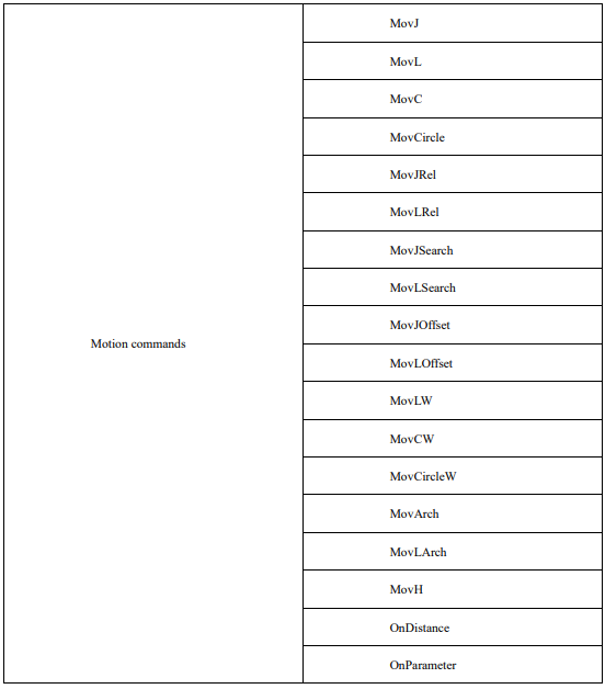
The list of motion commands:
MovJ
It indicates that each joint of the robot performs point-to-point motion. The end trajectory of the robot is an irregular curve, and the IO command can be operated when the command operates to an end. Description of the command parameters:
MovJ P [V] [B] [C] [Tool][Coord] [PayLoad][DO]
(Note: parameters indicated with [] are optional)
P: Target position (Target Pos)
Data type: APOS or CPOS variable
Meaning: The target point position in the coordinate system.
[V]: Target speed (Velo)
Data type: SPEED variable
Meaning: To specify the speed at which the robot executes MovJ. It includes the translational speed of the robots end effector, rotational speed, and speed of external axes, among others. The per component of the
SPEED variable is valid. If there are external axes present, the exj_l and exj_r components in the SPEED variable are valid as well.
Note: This parameter is optional and defaults to V4000.
[B]: Transition type (BlendType)
Data type: enum (FINE/RELATIVE/DEFAULT)
Meaning: The way of transition when the robot approaches the endpoint.
− FINE: No transition.
− RELATIVE: Relative transition.
− ABSOLUTE: Absolute transition.
− DEFAULT: Default type.
Note: This parameter is optional and defaults to FINE.
[C]: Transition Value (BlendValue)
Data type: ZONE variable
Meaning: The transition value when the robot approaches the endpoint.
Note: This parameter is optional and defaults to C100.
[Tool]: Tool Parameters (Tool)
Data type: TOOL variable
Meaning: The tool parameters used when the robot executes the path.
Note: This parameter is optional and defaults to to the current Tool Parameters set in the system.
[Coord]: Coordinate System Parameters (Coord)
Data type: USERCOOR variable
Meaning: The user coordinate system used by the robot when executing the path.
Note: This parameter is optional and defaults to defaults to the current Coordinate System Parameters set in the system.
[PayLoad]: Workpiece load (PayLoad)
Data type: PAYLOAD variable
Meaning: The workpiece load parameter used by the robot when executing the path.
Note: This parameter is optional and to the current payload parameter set in the system.
[DO]: IO operation to be performed after motion done (Add Do)
Data type: string
Meaning: The IO operation that can be triggered after the robot completes the command:
− NULL: No operation.
− IO commands: Perform IO operations. Currently supported IO instructions include SetDo, SetAo,
SetSimDo, SetSimAo, PulseOut, PulseSimOut, SetDO8421, SetDIEdge and SetSimDIEdge.
Example 1:

Example 2:

Example 3:


Example 4:

MovL
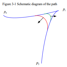
MovL is the linear motion command, through which the TCP point of the robot can be moved linearly to the target position at the set speed. If the start and end postures of the motion differ, then during operation the posture will synchronously rotate to the ending posture along with the position. It is the same as MovJ. An additional IO operation can be performed when the command is executed. The parameter setting of MovL is similar to MovJ. The command parameters are described as below:
MovLP [V] [B] [C][Tool][Coord] [PayLoad][O] [DO]
(Note: parameters indicated with [] are optional)
P: Target Position (Target Pos)
Data type: APOS or CPOS variable
Meaning: The target point position in the coordinate system.
[V]: Target speed (Velo)
Data type: SPEED variable
To specify the speed at which the robot executes MovL. It includes the translational speed of the robots end effector, rotational speed, and speed of external axes, among others. In this case, the tcp and ori components in the SPEED variable are valid. If there are external axes present, the exj_l and exj_r components in the SPEED variable are valid as well.
Note: This parameter is optional and defaults to V4000.
[B]: Transition type (BlendType)
Data type: enum (FINE/RELATIVE/DEFAULT)
Meaning: The way of transition when the robot approaches the endpoint.
− FINE: No transition.
− RELATIVE: Relative transition.
− ABSOLUTE: Absolute transition.
− DEFAULT: The type of default.
Note: This parameter is optional and defaults to FINE.
[C]: Transition Value (BlendValue)
Data type: ZONE variable
Meaning: The transition value when the robot approaches the endpoint.
Note: This parameter is optional and defaults to C100.
[Tool]: Tool Parameters (Tool)
Data type: TOOL variable
Meaning: The tool parameters used when the robot executes the path.
Note: This parameter is optional and defaults to the Tool Parameters set in the current system.
[Coord]: Coordinate System Parameters (Coord)
Data type: USERCOOR or EXTTCP or POSITIONER variable
Meaning: The user coordinate system/external TCP coordinate system/POSITIONER coordinate system used by the robot when executing the path.
Note: This parameter is optional and defaults to the Coordinate System Parameters set in the current system.
[PayLoad]: Workpiece load (PayLoad)
Data type: PAYLOAD variable
Meaning: The workpiece load parameter used by the robot when executing the path.
Note: This parameter is optional and defaults to the payload parameters set in the current system.
O: Rate type (OverrideType)
Data type: enum (GOVRON/GOVROFF)
− GOVRON: This path segment is affected by the Global Speed Multiplier.
− GOVROFF: This path segment is not affected by the Global Speed Multiplier.
Meaning: To set whether the current command path is affected by the Global Speed Multiplier.
Note: This parameter is optional and defaults to GOVRON.
[DO]: IO operations to be executed after motion done (Add Do)
Data type: string
Meaning: The IO operations that can be triggered after the robot completes the command:
− NULL: No operation.
− IO commands: Executing IO operation. The IO commands currently available are SetDo,
SetAo, SetSimDo, SetSimAo, PulseOut, PulseSimOut, SetDO8421, SetDIEdge,
SetSimDIEdge.
MovC
Arc command refers to the full-circle motion made by the robot’s TCP point from the starting position to the target by passing through the middle position. If the start and end postures of the motion are different, the posture will rotate to the end posture synchronously with the position, but it may not necessarily pass through the middle position.
MovCA P[V] [B] [C][Tool][Coord] [PayLoad][O] [DO]
(Note: parameters indicated with [] are optional)
A: Middle position (AuxPos)
Data type: APOS or CPOS variable
Meaning: The auxiliary point position used to determine the size of the arc and its motion direction. The orientation of this point does not affect the final path execution.
P: Target position (Target Pos)
Data type: APOS or CPOS variable
Meaning: The target point position in the coordinate system.
[V]: Target speed (Velo)
Data type: SPEED variable
Meaning: To specify the speed at which the robot executes MovC. It includes the translational speed of the robots end effector, rotational speed, and speed of external axes, among others. In this case, the tcp and ori components in the SPEED variable are valid. If there are external axes present, the exj_l and exj_r components in the SPEED variable are valid as well.
Note: This parameter is optional and defaults to V4000.
[B]: Transition type (BlendType)
Data type: enum (FINE/RELATIVE/DEFAULT)
Meaning: The way of transition when the robot approaches the endpoint
− FINE: No transition.
− RELATIVE: Relative transition.
− ABSOLUTE: Absolute transition.
− DEFAULT: The type of default.
Note: This parameter is optional and defaults to FINE.
[C]: Transition Value (BlendValue)
Data type: ZONE variable
Meaning: The transition value when the robot approaches the endpoint.
Note: This parameter is optional and defaults to C100.
[Tool]: Tool Parameters (Tool)
Data type: TOOL variable
Meaning: The tool parameters used when the robot executes the path.
Note: This parameter is optional and defaults to the Tool Parameters set in the current system.
[Coord]: Coordinate System Parameters (Coord)
Data type: USERCOOR or EXTTCP or POSITIONER variable
Meaning: The user coordinate system/external TCP coordinate system/POSITIONER coordinate system used by the robot when executing the path.
Note: This parameter is optional and defaults to the Coordinate System Parameters set in the current system.
[PayLoad]: Workpiece load (PayLoad)
Data type: PAYLOAD variable
Meaning: The workpiece load parameter used by the robot when executing the path.
Note: This parameter is optional and defaults to the payload parameters set in the current system.
O: Rate type (OverrideType)
Data type: enum (GOVRON/GOVROFF)
− GOVRON: This path segment is affected by the Global Speed Multiplier.
− GOVROFF: This path segment is not affected by the Global Speed Multiplier.
Meaning: To set whether the current command path is affected by the Global Speed Multiplier.
Note: This parameter is optional and defaults to GOVRON.
[DO]: IO operations to be executed after motion done (Add Do)
Data type: string
Meaning: The IO operations that can be triggered after the robot completes the command:
− NULL: No operation.
− IO COMMANDS: EXECUTING IO OPERATION. THE IO COMMANDS CURRENTLY
AVAILABLE ARESetDo, SetAo, SetSimDo, SetSimAo, PulseOut, PulseSimOut, SetDO8421,
SetDIEdge, SetSimDIEdge.
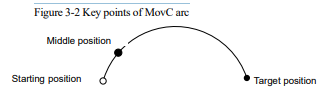
This command must satisfy:
To perform a full full-circle motion with the robot’s TCP end, two arc motion commands need to be executed.
MovCircle
MovCircle command means that the robot TCP point moves in a full circle from the start position to the start position through the auxiliary point 1 and auxiliary point 2 positions, with the pose remaining constant during the movement.
MovCircle A P[V] [B] [C][Tool] [Coord] [PayLoad] [O] [DO]
(Note: parameters indicated with [] are optional)
A: Middle position1 (AuxPos1)
Data type: APOS or CPOS variable
Meaning: The position 1 of the middle auxiliary point of the full circle, which is used to determine the size and movement direction of the arc. The pose of this point will not affect the final trajectory.
P: Middle position2 (AuxPos2)
Data type: APOS or CPOS variable
Meaning: The position 2 of the middle auxiliary point of the full circle, which is used to determine the size and movement direction of the arc. The pose of this point will not affect the final trajectory.
[V]: Target speed (Velo)
Data type: SPEED variable
Meaning: To specify the speed at which the robot executes MovCircle. It includes the translational speed of the robots end effector, rotational speed, and speed of external axes, among others. In this case, the tcp and ori components in the SPEED variable are valid. If there are external axes present, the exj_l and exj_r components in the SPEED variable are valid as well.
Note: This parameter is optional and defaults to V4000.
[B]: Transition type (BlendType)
Data type: enum (FINE/RELATIVE/DEFAULT)
Meaning: The way of transition when the robot approaches the endpoint.
− FINE: No transition.
− RELATIVE: Relative transition.
− ABSOLUTE: Absolute transition.
− DEFAULT: The type of default.
Note: This parameter is optional and defaults to FINE.
[C]: Transition Value (BlendValue)
Data type: ZONE variable
Meaning: The transition value when the robot approaches the endpoint.
Note: This parameter is optional and defaults to C100.
[Tool]: Tool Parameters (Tool)
Data type: TOOL variable
Meaning: The tool parameters used when the robot executes the path.
Note: This parameter is optional and defaults to the Tool Parameters set in the current system.
[Coord]: Coordinate System Parameters (Coord)
Data type: USERCOOR or EXTTCP or POSITIONER variable
Meaning: The user coordinate system/external TCP coordinate system/POSITIONER coordinate system used by the robot when executing the path.
Note: This parameter is optional and defaults to the Coordinate System Parameters set in the current system.
[PayLoad]: Workpiece load (PayLoad)
Data type: PAYLOAD variable
Meaning: The workpiece load parameter used by the robot when executing the path.
Note: This parameter is optional and defaults to the payload parameters set in the current system.
O: Rate type (OverrideType)
Data type: enum (GOVRON/GOVROFF)
− GOVRON: This path segment is affected by the Global Speed Multiplier.
− GOVROFF: This path segment is not affected by the Global Speed Multiplier.
Meaning: To set whether the current command path is affected by the Global Speed Multiplier.
Note: This parameter is optional and defaults to GOVRON.
[DO]: IO operations to be executed after motion done (Add Do)
Data type: string
Meaning: The IO operations that can be triggered after the robot completes the command:
− NULL: No operation.
− IO commands: executing io operation. The IO commands currently available are SetDo, SetAo,
SetSimDo, SetSimAo, PulseOut, PulseSimOut, SetDO8421, SetDIEdge, SetSimDIEdge
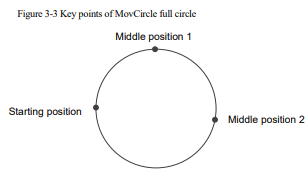
The command must adhere to the following specifications:
When teaching the points for the circular path, the "Middle position1" or "Middle position2" should not be too close to the starting point. The distance between "Middle position1" and "Middle position2" should also not be too close. Otherwise, it will trigger an alarm of "Calculating arc auxiliary information error";
The robots orientation remains constant during the full-circle motion;
During the full-circle motion, transitions are supported, and the command speed is not affected by the Global Multiplier;
If the starting point is in a singular position, cross-singularity mode must be enabled to execute the full-circle motion;
External TCP functionality supports full-circle motion;
Variable positioner and linear guides support full-circle motion, but it is crucial to ensure that the additional axis position remains unchanged during the full-circle motion;
Conveyor tracking functionality does not support full-circle motion;
MovJRel
The MovJ interpolation relative offset command. It works by taking the current robot position or the target position of the previous motion command as the starting point, and then perform the robot motion operation.
Unlike the commands such as MovJ, the target relative position value used by this command cannot be obtained through teaching. User needs to create a new joint relative position variable in the list of variables before, and then select it from the drop-down list. The parameters are defined as follows.
MovJRelP[V] [B] [C] [PayLoad][DO]
(Note: parameters indicated with [] are optional)
P: Target Relative Position (RelPos)
Data type: DAPOS variable
Meaning: The position increment the robot will move when executing this command.
[V]: Target speed (Velo)
Data type: SPEED variable
Meaning: To specify the speed at which the robot executes MovJRel. It includes the translational speed of the robots end effector, rotational speed, and speed of external axes, among others. In this case, the per component in the SPEED variable is valid. If there are external axes present, the exj_l and exj_r components in the SPEED variable are valid as well.
Note: This parameter is optional and defaults to V4000.
[B]: Transition type (BlendType)
Data type: enum (FINE/RELATIVE/DEFAULT)
Meaning: The way of transition when the robot approaches the endpoint.
− FINE: No transition.
− RELATIVE: Relative transition.
− ABSOLUTE: Absolute transition.
− DEFAULT: The type of default.
Note: This parameter is optional and defaults to FINE.
[C]: Transition Value (BlendValue)
Data type: ZONE variable
Meaning: The transition value when the robot approaches the endpoint.
Note: This parameter is optional and defaults to C100.
[PayLoad]: Workpiece load (PayLoad)
Data type: PAYLOAD variable
Meaning: The workpiece load parameter used by the robot when executing the path.
Note: This parameter is optional and defaults to the payload parameters set in the current system.
[DO]: IO operations to be executed after motion done (Add Do)
Data type: string
Meaning: The IO operations that can be triggered after the robot completes the command:
− NULL: No operation.
− IO COMMANDS: EXECUTING IO OPERATION. THE IO COMMANDS CURRENTLY
AVAILABLE ARESetDo, SetAo, SetSimDo, SetSimAo, PulseOut, PulseSimOut, SetDO8421,
SetDIEdge, SetSimDIEdge.
Example 1:

Example 2:

MovLRel
This command is used for relative linear motion. The command always starts from the current robot position or the target position of the previous motion command, and the robot moves relative to the specified displacement or orientation offset. Transition parameters can also be set, similar to MovJRel. The parameters are defined as shown in the following diagram:
MovLRelPT [V] [B] [C][PayLoad][O] [DO]
(Note: parameters indicated with [] are optional)
P: Target Relative Position (RelPos)
Data type: DCPOS variable
Meaning: The position increment the robot will move when executing this command.
T: Reference Coordinate System (RefSys)
Data type: enum (COORD/TOOL)
− COORD: Reference Coordinate System (RefSys).
− TOOL: Tool coordinate system.
Meaning: Reference coordinate system: Cartesian or Tool.
[V]: Target speed (Velo)
Data type: SPEED variable
Meaning: To specify the speed at which the robot executes MovLRel. It includes the translational speed of the robots end eff ector, rotational speed, and speed of external axes, among others. In this case, the tcp and ori components in the SPEED variable are valid. If there are external axes present, the exj_l and exj_r components in the SPEED variable are valid as well.
Note: This parameter is optional and defaults to V4000.
[B]: Transition type (BlendType)
Data type: enum (FINE/RELATIVE/DEFAULT)
Meaning: The way of transition when the robot approaches the endpoint.
− FINE: No transition.
− RELATIVE: Relative transition.
− ABSOLUTE: Absolute transition.
− DEFAULT: The type of default.
Note: This parameter is optional and defaults to FINE
[C]: Transition Value (BlendValue)
Data type: ZONE variable
Meaning: The transition value when the robot approaches the endpoint.
Note: This parameter is optional and defaults to C100.
[PayLoad]: Workpiece load (PayLoad)
Data type: PAYLOAD variable
Meaning: The workpiece load parameter used by the robot when executing the path.
Note: This parameter is optional and defaults to the payload parameters set in the current system.
O: Rate type (OverrideType)
Data type: enum (GOVRON/GOVROFF)
− GOVRON: This path segment is affected by the Global Speed Multiplier.
− GOVROFF: This path segment is not affected by the Global Speed Multiplier.
Meaning: To set whether the current command path is affected by the Global Speed Multiplier.
Note: This parameter is optional and defaults to GOVRON.
[DO]: IO operations to be executed after motion done (Add Do)
Data type: string
Meaning: The IO operations that can be triggered after the robot completes the command:
− NULL: No operation.
− IO COMMANDS: EXECUTING IO OPERATION. THE IO COMMANDS CURRENTLY
AVAILABLE ARESetDo, SetAo, SetSimDo, SetSimAo, PulseOut, PulseSimOut, SetDO8421,
SetDIEdge, SetSimDIEdge.
Example 1:

Example 2:

MovJSearch
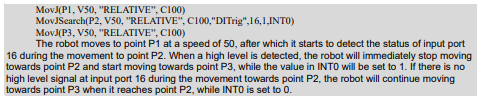
A search command. It performs IO detection or torque detection when executing the MovL command.
When the search condition is IO detection, if the indexed IO value reaches the Trigger value, the execution of the current command is stopped, and the next command is continued.
When the search condition is torque detection, if the indexed axis torque value reaches the Trigger value, the execution of the current command is stopped, and the next command is continued.
Please note that this command interrupts the transition.
The command parameters are defined as follows:
MovJSearchP [V] [B] [C][Tool][Coord] [PayLoad]Type Number Value [StopType]
[StopDecScale] R SearchP Goto [DO]
(Note: parameters indicated with [] are optional)
P: Target position (Target Pos)
Data type: APOS or CPOS variable
Meaning: The target point position in the coordinate system.
[V]: Target speed (Velo)
Data type: SPEED variable
Meaning: To specify the speed at which the robot executes MovJSearch. It includes the translational speed of the robots end effector, rotational speed, and speed of external axes, among others. In this case, the per component in the SPEED variable is valid. If there are external axes present, the exj_l and exj_r components in the SPEED variable are valid as well.
Note: This parameter is optional and defaults to V4000.
[B]: Transition type (BlendType)
Data type: enum (FINE/RELATIVE/DEFAULT)
Meaning: The way of transition when the robot approaches the endpoint.
− FINE: No transition.
− DEFAULT: The type of default.
Note: This parameter is optional and defaults to FINE.
[C]: Transition Value (BlendValue)
Data type: ZONE
Meaning: The transition value when the robot approaches the endpoint.
Note: This parameter is optional and defaults to C100.
[Tool]: Tool Parameters (Tool)
Data type: TOOL variable
Meaning: The tool parameters used when the robot executes the path.
Note: This parameter is optional and defaults to the Tool Parameters set in the current system.
[Coord]: Coordinate System Parameters (Coord)
Data type: USERCOOR variable
Meaning: The user coordinate system used by the robot when executing the path.
Note: This parameter is optional and defaults to the Coordinate System Parameters set in the current system.
[PayLoad]: Workpiece load (PayLoad)
Data type: PAYLOAD variable
Meaning: The workpiece load parameter used by the robot when executing the path.
Note: This parameter is optional and defaults to the payload parameters set in the current system.
Type: Type of detection (SearchType)
Data type: enum (DITrig/AITrig/SIMDITrig/SIMAITrig/TorqTrig)
− DITrig: Physical digital input trigger.
− AITrig: Physical analog input trigger.
− SIMDITrig: Virtual digital input trigger.
− SIMAITrig: Virtual analog input trigger.
− TorqTrig: Torque trigger.
Meaning: The type of operation to be monitored when the robot runs the path.
Number: Trigger index (SearchIndex)
Data type: int
Meaning: The Trigger index number to be monitored when the robot runs the path. For example, in the case of
DITrig trigger, this index number corresponds to the input port to be monitored. In the case of TorqTrig trigger, this index number corresponds to the axis to be monitored.
Value: Trigger value (SearchValue)
Data type: real
Meaning: The threshold value to be detected when the robot runs the path. For example, in the case of DITrig trigger, this value represents the high or low logic level to be detected on a specific input port. In the case of TorqTrig trigger, this value represents the rated torque permillage of a specific axis.
StopType: STOP type (StopType)
Data type: enum (HARDSTOP/SOFTSTOP/DEFAULT)
− HARDSTOP: Stops immediately;
− SOFTSTOP: Stop at reduced speed;
− DEFAULT: The type of default.
Meaning: The way to stop when a signal is detected.
Note: This parameter is optional and defaults to HARDSTOP.
StopDecScale: Decel Factor (StopDecScale)
Data type: real.
Meaning: The value is valid when "SOFTSTOP" is selected as "Stop Type". It is used to adjust the
Decel/Accel factor, the greater the value, the faster the deceleration.
R: Returned value (ResultV)
Data type: INT variable
Meaning: To return the status of the command execution upon completion. Returning 0 indicates that the condition triggering the command was not satisfied, returning 1 indicates that the condition triggering the command was satisfied, and returning 2 indicates that the condition triggering the command was satisfied at the motion starting point.
SearchP: Position of successful search (SearchPos)
Data type: APOS
Meaning: To return the coordinate position of the robot when the condition triggering the command is satisfied.
Note: This parameter is optional.
Goto: Label name to jump to in case of a search failure (LabelName)
Data type: label.
Meaning: The name of the label to which the program pointer will jump in case of a search failure.
This parameter is optional. If set to default, the system will not jump to the specified label for execution in case of a search failure.
[DO]: IO operations to be executed after motion done (Add Do)
Data type: string
Meaning: The IO operations that can be triggered after the robot completes the command:
− NULL: No operation.
− IO COMMANDS: EXECUTING IO OPERATION. THE IO COMMANDS CURRENTLY
AVAILABLE ARESetDo, SetAo, SetSimDo, SetSimAo, PulseOut, PulseSimOut, SetDO8421,
SetDIEdge, SetSimDIEdge.
Example 1:
MovLSearch
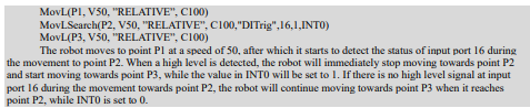
The Search Ccommand. It refers to IO detection or torque detection while executing this MovL command, which is similar to MovJSearch.
When the search condition is of IO detection and the value of the indexed IO reaches the trigger value, stop running this command and continue to execute the next command
When the search condition is of torque detection and the value of the index axis torque reaches the trigger value, stop running the command and continue to execute the next command.
Please note that this command will interrupt the transition.
The specific command parameters are defined as follows:
MovLSearchP [V] [B] [C][Tool][Coord] [PayLoad]Type Number Value [StopType] [StopDecScale] R SearchP Goto [DO]
(Note: parameters indicated with [] are optional)
P: Target position (Target Pos)
Data type: APOS or CPOS variable
Meaning: The target point position in the coordinate system.
[V]: Target speed (Velo)
Data type: SPEED variable
Meaning: To specify the speed at which the robot executes MovJSearch. It includes the translational speed of the robots end effector, rotational speed, and speed of external axes, among others. In this case, the tcp and ori components in the SPEED variable are valid. If there are external axes present, the exj_l and exj_r components in the SPEED variable are valid as well.
Note: This parameter is optional and defaults to V4000.
[B]: Transition type (BlendType)
Data type: enum (FINE/RELATIVE/DEFAULT)
Meaning: The way of transition when the robot approaches the endpoint.
− FINE: No transition.
− DEFAULT: The type of default.
Note: This parameter is optional and defaults to FINE.
[C]: Transition Value (BlendValue)
Data type: ZONE
Meaning: The transition value when the robot approaches the endpoint.
Note: This parameter is optional and defaults to C100.
[Tool]: Tool Parameters (Tool)
Data type: TOOL variable
Meaning: The tool parameters used when the robot executes the path.
Note: This parameter is optional and defaults to the Tool Parameters set in the current system.
[Coord]: Coordinate System Parameters (Coord)
Data type: USERCOOR or EXTTCP or POSITIONER variable
Meaning: The user coordinate system/external TCP coordinate system/POSITIONER coordinate system used by the robot when executing the path.
Note: This parameter is optional and defaults to the Coordinate System Parameters set in the current system.
[PayLoad]: Workpiece load (PayLoad)
Data type: PAYLOAD variable
Meaning: The workpiece load parameter used by the robot when executing the path.
Note: This parameter is optional and defaults to the payload parameters set in the current system.
Type: Type of detection (SearchType)
Data type: enum (DITrig/AITrig/SIMDITrig/SIMAITrig/TorqTrig)
− DITrig: Physical digital input trigger.
− AITrig: Physical analog input trigger.
− SIMDITrig: Virtual digital input trigger.
− SIMAITrig: Virtual analog input trigger.
− TorqTrig: Torque trigger.
Meaning: The type of operation to be monitored when the robot runs the path.
Number: Trigger index (SearchIndex)
Data type: int
Meaning: The Trigger index number to be monitored when the robot runs the path. For example, in the case of DITrig trigger, this index number corresponds to the input port to be monitored. In the case of TorqTrig trigger, this index number corresponds to the axis to be monitored.
Value: Trigger value (SearchValue)
Data type: real
Meaning: The threshold value to be detected when the robot runs the path. For example, in the case of DITrig trigger, this value represents the high or low logic level to be detected on a specific input port. In the case of TorqTrig trigger, this value represents the rated torque permillage of a specific axis.
StopType: STOP type (StopType)
Data type: enum (HARDSTOP/SOFTSTOP/DEFAULT)
− HARDSTOP: Stops immediately.
− SOFTSTOP: Stop at reduced speed.
− DEFAULT: The type of default.
Meaning: The way to stop when a signal is detected.
Note: This parameter is optional and defaults to HARDSTOP.
StopDecScale: Decel Factor (StopDecScale)
Data type: real.
Meaning: The value is valid when "SOFTSTOP" is selected as "Stop Type". It is used to adjust the Decel/Accel factor, the greater the value, the faster the deceleration.
R: Returned value (ResultV)
Data type: INT variable
Meaning: To return the execution status of this command. Returning 0 indicates that the condition triggering the command was not satisfied and the execution ended. Returning 1 indicates that the condition triggering the command was satisfied and the execution ended. Returning 2 indicates that the condition triggering the command was satisfied at the starting point of the motion and the execution ended.
SearchP: Position of successful search (SearchPos)
Data type: CPOS
Meaning: To return the coordinate position of the robot when the condition triggering the command is satisfied.
Note: This parameter is optional.
Goto: Label name to jump to in case of a search failure (LabelName)
Data type: label.
Meaning: The name of the label to which the program pointer will jump in case of a search failure.
This parameter is optional. If set to default, the system will not jump to the specified label for execution in case of a search failure.
[DO]: IO operations to be executed after motion done (Add Do)
Data type: string
Meaning: The IO operations that can be triggered after the robot completes the command:
− NULL: No operation.
− IO COMMANDS: EXECUTING IO OPERATION. THE IO COMMANDS CURRENTLY
AVAILABLE ARESetDo, SetAo, SetSimDo, SetSimAo, PulseOut, PulseSimOut, SetDO8421,
SetDIEdge, SetSimDIEdge.
Example 1:
MovJOffset
The Joint Space Offset command. It refers to a relative motion starting from a specified reference position, relative to a coordinate system or tool. The only difference from MovJRel is that this command specifies the starting point of the offset motion, which may not be the current position or the endpoint of the previous command. Other functionalities remain the same.
The specific command parameters are defined as follows:
MovJOffset RP TP T Tool Coord [V] [B] [C][PayLoad][O] [DO]
(Note: parameters indicated with [] are optional)
RP: Reference position (RefPos)
Data type: APOS or CPOS variable
Meaning: The position of the reference point in the coordinate system
TP: Target Relative Position (RelPos)
Data type: DCPOS or DAPOS variable
Meaning: The position increment relative to the reference position
T: Reference Coordinates (RefSys)
Data type: enum (COORD/TOOL)
− COORD: The user coordinate system.
− TOOL: The tool coordinate system.
Meaning: The reference coordinate system, either Cartesian or Tool.
Tool: Tool Parameters (Tool)
Data type: TOOL variable
Meaning: The tool parameters used when the robot executes the path.
Coord: Coordinate System Parameters (Coord)
Data type: USERCOOR variable
Meaning: The user coordinate system used by the robot when executing the path.
[V]: Target speed (Velo)
Data type: SPEED variable
Meaning: To specify the speed at which the robot performs the MovJOffset command. Please note that only the "per" component of the SPEED variable is valid in this context.
Note: This parameter is optional and defaults to V4000.
[B]: Transition type (BlendType)
Data type: enum (FINE/RELATIVE/DEFAULT)
Meaning: The way of transition when the robot approaches the endpoint.
− FINE: No transition.
− RELATIVE: Relative transition.
− ABSOLUTE: Absolute transition.
− DEFAULT: The type of default.
Note: This parameter is optional and defaults to FINE.
[C]: Transition Value (BlendValue)
Data type: ZONE
Meaning: The transition value when the robot approaches the endpoint.
Note: This parameter is optional and defaults to C100.
[PayLoad]: Workpiece load (PayLoad)
Data type: PAYLOAD variable
Meaning: The workpiece load parameter used by the robot when executing the path.
Note: This parameter is optional and defaults to the payload parameters set in the current system.
[DO]: IO operations to be executed after motion done (Add Do)
Data type: string
Meaning: The IO operations that can be triggered after the robot completes the command:
− NULL: No operation.
− IO COMMANDS: EXECUTING IO OPERATION. THE IO COMMANDS CURRENTLY AVAILABLE ARESetDo, SetAo, SetSimDo, SetSimAo, PulseOut, PulseSimOut, SetDO8421, SetDIEdge, SetSimDIEdge.
Example 1:

MovLOffset
The Linear Offset command. Itspecifies a reference position as the starting point and performs a relative offset motion with respect to the coordinate system or tool. The key difference from MovLRel is that this command explicitly specifies the starting point for the offset motion, which may not necessarily be the current position or the endpoint of the previous instruction, while other functionalities remain the same.
The specific command parameters are defined as follows:
MovLOffset RPTP T Tool Coord [V] [B] [C][PayLoad][O] [DO]
(Note: parameters indicated with [] are optional)
RP: Reference position (RefPos)
Data type: APOS or CPOS variable
Meaning: The position of the reference point in the coordinate system
TP: Target Relative Position (RelPos)
Data type: DCPOS variable
Meaning: The position increment relative to the reference position
T: Reference coordinate system (RefSys)
Data type: enum (COORD/TOOL)
− COORD: The Cartesian coordinate system.
− TOOL: The tool coordinate system.
Meaning: Reference Coordinates: either Cartesian or Tool
Tool: Tool Parameters (Tool)
Data type: TOOL variable
Meaning: The tool parameters used when the robot executes the path.
Coord: Coordinate System Parameters (Coord)
Data type: USERCOOR variable
Meaning: The user coordinate system used by the robot when executing the path.
[V]: Target speed (Velo)
Data type: SPEED variable
Meaning: To specify the speed at which the robot executes MovLOffset. It includes the translational speed of the robots end effector, rotational speed, and speed of external axes, among others. In this case, the tcp and ori components in the SPEED variable are valid. If there are external axes present, the exj_l and exj_r components in the SPEED variable are valid as well.
Note: This parameter is optional and defaults to V4000.
[B]: Transition type (BlendType)
Data type: enum (FINE/RELATIVE/DEFAULT)
Meaning: The way of transition when the robot approaches the endpoint.
− FINE: No transition.
− RELATIVE: Relative transition.
− ABSOLUTE: Absolute transition.
− DEFAULT: The type of default.
Note: This parameter is optional and defaults to FINE.
[C]: Transition Value (BlendValue)
Data type: ZONE
Meaning: The transition value when the robot approaches the endpoint.
Note: This parameter is optional and defaults to C100.
[PayLoad]: Workpiece load (PayLoad)
Data type: PAYLOAD variable
Meaning: The workpiece load parameter used by the robot when executing the path.
Note: This parameter is optional and defaults to the payload parameters set in the current system.
O: Rate type (OverrideType)
Data type: enum (GOVRON/GOVROFF)
− GOVRON: This path segment is affected by the Global Speed Multiplier.
− GOVROFF: This path segment is not affected by the Global Speed Multiplier.
Meaning: To set whether the current command path is affected by the Global Speed Multiplier.
Note: This parameter is optional and defaults to GOVRON.
[DO]: IO operations to be executed after motion done (Add Do)
Data type: string
Meaning: The IO operations that can be triggered after the robot completes the command:
− NULL: No operation.
− IO COMMANDS: EXECUTING IO OPERATION. THE IO COMMANDS CURRENTLY
AVAILABLE ARESetDo, SetAo, SetSimDo, SetSimAo, PulseOut, PulseSimOut, SetDO8421,
SetDIEdge, SetSimDIEdge.
Example 1:

MovLW
The WEAVE Motion command. It refers to the weave motion performed along the arc direction by setting the weave frequency and weave mplitude.
The parameters for this command are defined as shown in the diagram:
MovLWP [V] [B] [C][Tool][Coord] [PayLoad]WEAVE [O] [DO]
(Note: parameters indicated with [] are optional)
P: Target position (Target Pos)
Data type: APOS or CPOS variable
Meaning: The target point position in the coordinate system.
[V]: Target speed (Velo)
Data type: SPEED variable
Meaning: To specify the speed at which the robot executes MovLW. It includes the translational speed of the robots end effector, rotational speed, and speed of external axes, among others. In this case, the tcp and ori components in the SPEED variable are valid. If there are external axes present, the exj_l and exj_r components in the SPEED variable are valid as well.
Note: This parameter is optional and defaults to V4000.
[B]: Transition type (BlendType)
Data type: enum (FINE/RELATIVE/DEFAULT)
Meaning: The way of transition when the robot approaches the endpoint.
− FINE: No transition.
− RELATIVE: Relative transition.
− ABSOLUTE: Absolute transition.
− DEFAULT: The type of default.
Note: This parameter is optional and defaults to FINE.
[C]: Transition Value (BlendValue)
Data type: ZONE
Meaning: The transition value when the robot approaches the endpoint.
Note: This parameter is optional and defaults to C100.
[Tool]: Tool Parameters (Tool)
Data type: TOOL variable
Meaning: The tool parameters used when the robot executes the path.
Note: This parameter is optional and defaults to the Tool Parameters set in the current system.
[Coord]: Coordinate System Parameters (Coord)
Data type: USERCOOR or POSITIONER variable
Meaning: The user coordinate system/positioner coordinate system used by the robot to execute the path.
Note: This parameter is optional and defaults to the Coordinate System Parameters set in the current system.
[PayLoad]: Workpiece load (PayLoad)
Data type: PAYLOAD variable
Meaning: The workpiece load parameter used by the robot when executing the path.
Note: This parameter is optional and defaults to the payload parameters set in the current system.
WEAVE: WEAVE variable (Weave Value)
Data type: WEAVE variable
Meaning: The parameter set for the robots weave motion, which includes the weave frequency, weave amplitude, dwell time, rotation, and other related parameters.
O: Rate type (OverrideType)
Data type: enum (GOVRON/GOVROFF)
− GOVRON: This path segment is affected by the Global Speed Multiplier.
− GOVROFF: This path segment is not affected by the Global Speed Multiplier.
Meaning: To set whether the current command path is affected by the Global Speed Multiplier.
Note: This parameter is optional and defaults to GOVRON.
[DO]: IO operations to be executed after motion done (Add Do)
Data type: string
Meaning: The IO operations that can be triggered after the robot completes the command:
− NULL: No operation.
− IO COMMANDS: EXECUTING IO OPERATION. THE IO COMMANDS CURRENTLY AVAILABLE ARESetDo, SetAo, SetSimDo, SetSimAo, PulseOut, PulseSimOut, SetDO8421, SetDIEdge, SetSimDIEdge.
MovCW
The Circular Weave command. It refers to the weave motion performed along the arc direction by setting the weave frequency and weave mplitude.
The parameters for this command are defined as shown in the diagram:
MovCW AP [V] [B] [C][Tool][Coord] [PayLoad]WEAVE [O] [DO]
(Note: parameters indicated with [] are optional)
A: Middle position (AuxPos)
Data type: APOS or CPOS variable
Meaning: The auxiliary point position used to determine the size of the arc and its motion direction. The orientation of this point does not affect the final path execution.
P: Target position (Target Pos)
Data type: APOS or CPOS variable
Meaning: The target point position in the coordinate system.
[V]: Target speed (Velo)
Data type: SPEED variable
Meaning: To specify the speed at which the robot executes MovCW. It includes the translational speed of the robots end effector, rotational speed, and speed of external axes, among others. In this case, the tcp and ori components in the SPEED variable are valid. If there are external axes present, the exj_l and exj_r components in the SPEED variable are valid as well.
Note: This parameter is optional and defaults to V4000.
[B]: Transition type (BlendType)
Data type: enum (FINE/RELATIVE/DEFAULT)
Meaning: The way of transition when the robot approaches the endpoint.
− FINE: No transition.
− RELATIVE: Relative transition.
− ABSOLUTE: Absolute transition.
− DEFAULT: The type of default.
Note: This parameter is optional and defaults to FINE.
[C]: Transition Value (BlendValue)
Data type: ZONE
Meaning: The transition value when the robot approaches the endpoint.
Note: This parameter is optional and defaults to C100.
[Tool]: Tool Parameters (Tool)
Data type: TOOL variable
Meaning: The tool parameters used when the robot executes the path.
Note: This parameter is optional and defaults to the Tool Parameters set in the current system.
[Coord]: Coordinate System Parameters (Coord)
Data type: USERCOOR or POSITIONER variable
Meaning: The user coordinate system/positioner coordinate system used by the robot to execute the path.
Note: This parameter is optional and defaults to the Coordinate System Parameters set in the current system.
[PayLoad]: Workpiece load (PayLoad)
Data type: PAYLOAD variable
Meaning: The workpiece load parameter used by the robot when executing the path.
Note: This parameter is optional and defaults to the payload parameters set in the current system.
WEAVE: WEAVE variable (Weave Value)
Data type: WEAVE variable
Meaning: The parameter set for the robots weave motion, which includes the weave frequency, weave amplitude, dwell time, rotation, and other related parameters.
O: Rate type (OverrideType)
Data type: enum (GOVRON/GOVROFF)
− GOVRON: This path segment is affected by the Global Speed Multiplier.
− GOVROFF: This path segment is not affected by the Global Speed Multiplier.
Meaning: To set whether the current command path is affected by the Global Speed Multiplier.
Note: This parameter is optional and defaults to GOVRON.
[DO]: IO operations to be executed after motion done (Add Do)
Data type: string
Meaning: The IO operations that can be triggered after the robot completes the command:
− NULL: No operation.
− IO COMMANDS: EXECUTING IO OPERATION. THE IO COMMANDS CURRENTLY
AVAILABLE ARESetDo, SetAo, SetSimDo, SetSimAo, PulseOut, PulseSimOut, SetDO8421,
SetDIEdge, SetSimDIEdge.
MovCircleW
The Circle Weave command. It allows the robot to maintain continuous weave motion during a full circle movement.
The supported weave motions currently include sinusoidal weave and triangular weave.
The parameters for this command are defined as shown in the diagram:
MovCircleW A P [V] [B] [C] [Tool] [Coord] [PayLoad] WEAVE [O] [DO]
(Note: parameters indicated with [] are optional)
A: Middle position1 (AuxPos1)
Data type: APOS or CPOS variable
Meaning: The middle position 1, which is used to determine the size and direction of the circular arc during a full-circle motion. The posture of this point does not affect the final path execution.
P: Middle position2 (AuxPos2)
Data type: APOS or CPOS variable
Meaning: The middle position 2, which is used to determine the size and direction of the circular arc during a full-circle motion. The posture of this point does not affect the final path execution.
[V]: Target speed (Velo)
Data type: SPEED variable
Meaning: To specify the speed at which the robot executes MovCircleW. It includes the translational speed of the robots end effector, rotational speed, and speed of external axes, among others. In this case, the tcp and ori components in the SPEED variable are valid. If there are external axes present, the exj_l and exj_r components in the SPEED variable are valid as well.
Note: This parameter is optional and defaults to V4000.
[B]: Transition type (BlendType)
Data type: enum (FINE/RELATIVE/DEFAULT)
Meaning: The way of transition when the robot approaches the endpoint.
− FINE: No transition.
− RELATIVE: Relative transition.
− ABSOLUTE: Absolute transition.
− DEFAULT: The type of default.
Note: This parameter is optional and defaults to FINE.
[C]: Transition Value (BlendValue)
Data type: ZONE
Meaning: The transition value when the robot approaches the endpoint.
Note: This parameter is optional and defaults to C100.
[Tool]: Tool Parameters (Tool)
Data type: TOOL variable
Meaning: The tool parameters used when the robot executes the path
Note: This parameter is optional and defaults to the Tool Parameters set in the current system.
[Coord]: Coordinate System Parameters (Coord)
Data type: USERCOOR or POSITIONER variable
Meaning: The user coordinate system/positioner coordinate system used by the robot to execute the path.
Note: This parameter is optional and defaults to the Coordinate System Parameters set in the current system.
[PayLoad]: Workpiece load (PayLoad)
Data type: PAYLOAD variable
Meaning: The workpiece load parameter used by the robot when executing the path.
Note: This parameter is optional and defaults to the payload parameters set in the current system.
WEAVE: WEAVE variable (Weave Value)
Data type: WEAVE variable
Meaning: The parameter set for the robots weave motion, which includes the weave frequency, weave amplitude, dwell time, rotation, and other related parameters.
O: Rate type (OverrideType)
Data type: enum (GOVRON/GOVROFF)
− GOVRON: This path segment is affected by the Global Speed Multiplier.
− GOVROFF: This path segment is not affected by the Global Speed Multiplier.
Meaning: To set whether the current command path is affected by the Global Speed Multiplier.
Note: This parameter is optional and defaults to GOVRON.
[DO]: IO operations to be executed after motion done (Add Do)
Data type: string
Meaning: The IO operations that can be triggered after the robot completes the command:
− NULL: No operation.
− IO COMMANDS: EXECUTING IO OPERATION. THE IO COMMANDS CURRENTLY AVAILABLE ARESetDo, SetAo, SetSimDo, SetSimAo, PulseOut, PulseSimOut, SetDO8421, SetDIEdge, SetSimDIEdge.
OnDistance
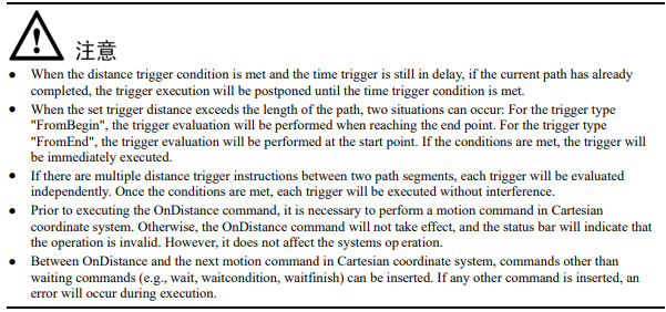
The Distance Trigger command. It allows the controller to perform certain actions, such as assigning values or setting IO, when the robot moves a specified distance from the start or end point of a linear or circular path, without interrupting the transition.
The parameter definitions for this command are as follows:
OnDistance TypeDistTimeMs DO
Type: Trigger type (Type)
Data type: enum (FromBegin/FromEnd)
− FromBegin: Trigger from the start point.
− FromEnd: Trigger from the end point.
Meaning: The method to detect the distance trigger. It determines whether the trigger distance is calculated from the start or end point
Dist: Trigger distance (TrigDis)
Data type: real or REAL variable
Meaning: The distance relative to the start or end point that triggers the action.
TimeMs: The distance relative to the start or end point that triggers the action.
Data type: int or INT variable
Meaning: The delay time after meeting the trigger condition before executing the action. This value can be negative, where a negative value indicates a forward delay trigger.
DO: IO operation to be executed after motion done (Do)
Data type: string
Meaning: To specify the command operation to be triggered when the robot meets the trigger condition. These operations can include assignment commands and IO commands.
When the trigger type is set to "FromBegin", the controller enters the trigger wait state after the robot moves the specified distance from the start point. After the delay trigger time, the related trigger operation is executed.
When the trigger type is set to "FromEnd", the controller enters the trigger wait state after the robot moves the specified distance from the end point. After the delay trigger time, the related trigger operation is executed.
Example 1: Execute the Do operation with a delay of 100ms when the distance from the start point to P2 on the trajectory from P1 to P2 is 200mm.

Example 2: Execute the Do operation with a delay of 100ms when the distance from the start point to P2 on the trajectory from P1 to P2 is 200mm.

OnParameter
The Distance Percentage Trigger command. It is used to trigger certain operations, such as assigning values or setting IO, at a specific location along the motion paths without interrupting the transitions. When the robot reaches the defined percentage of the path, the controller enters a trigger waiting state. After a specified delay time, it proceeds to execute the associated trigger operations.
The parameter definitions for this command are as follows:
OnParameter Percence TimeMsDO
Perence: Trigger Type (Type)
Data type: int
Meaning: The percentage of the path where the trigger should occur
TimeMs: Trigger Time (TrigTime)
Data type: int or INT variable
Meaning: The delay time after satisfying the trigger condition. Negative values indicate a delay towards the beginning of the motion.
DO: IO operations to be executed after motion done (Do)
Data type: string
Meaning: The command operations that can be triggered when the robot satisfies the trigger condition, including assignment instructions and IO commands.
Example:

MovArch
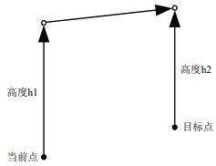
The joint arc motion comand for SCARA robot models. It is executed in the form of MovJ to complete a path. The entire motion process involves the following steps: first, the robot lifts to a height of h1 at the current point, then moves to a height of h2 relative to the target point, and finally descends by a height of h2 to reach the target point, thereby accomplishing an arc motion. Similar to regular motion instructions, additional I/O operations can be performed upon completion of this command. The Target Speed of this command is specified as a percentage.
Note: This command is currently only applicable to SCARA robot models and does not support six axis robots.
The command parameters are described as below:
MovArchP [V] [B] [C][Tool][Coord] [PayLoad]H H2Z [DO]
(Note: parameters indicated with [] are optional)
P: Target position (Target Pos)
Data type: APOS or CPOS variable
Meaning: The target point position in the coordinate system.
[V]: Target speed (Velo)
Data type: SPEED variable
Meaning: To specify the speed at which the robot executes MovL. It includes the translational speed of the robots end effector, rotational speed, and speed of external axes, among others. In this case, the per component in the SPEED variable is valid. If there are external axes present, the exj_l and exj_r components in the SPEED variable are valid as well.
Note: This parameter is optional and defaults to V4000.
[B]: Transition type (BlendType)
Data type: enum (FINE/RELATIVE/DEFAULT)
Meaning: The way of transition when the robot approaches the endpoint.
− FINE: No transition.
− RELATIVE: Relative transition.
− ABSOLUTE: Absolute transition.
− DEFAULT: The type of default.
Note: This parameter is optional and defaults to FINE.
[C]: Transition Value (BlendValue)
Data type: ZONE
Meaning: When the robot approaches the endpoint, the Transition Value (a ZONE-type variable) is utilized. In this context, the "per" parameter corresponds to the relative transition type, while the "dis" parameter corresponds to the absolute transition type.
Note: This parameter is optional and defaults to C100.
[Tool]: Tool Parameters (Tool)
Data type: TOOL variable
Meaning: The tool parameters used when the robot executes the path.
Note: This parameter is optional and defaults to the Tool Parameters set in the current system.
[Coord]: Coordinate System Parameters (Coord)
Data type: USERCOOR variable
Meaning: The user coordinate system used by the robot when executing the path.
Note: This parameter is optional and defaults to the Coordinate System Parameters set in the current system.
[PayLoad]: Workpiece load (PayLoad)
Data type: PAYLOAD variable
Meaning: The workpiece load parameter used by the robot when executing the path.
Note: This parameter is optional and defaults to the payload parameters set in the current system.
H: Lifting height (Lift High)
Data type: real
Meaning: The height that the robot needs to lift during the arc motion.
H2: Drop height Drop High)
Data type: real
Meaning: The height that the robot needs to descend during the arc motion.
Z: CornerValue
Data type: ZONE
Meaning: The corner value that the robot follows during the arc motion.
[DO]: IO operations to be executed after motion done (Add Do)
Data type: string
Meaning: The IO operations that can be triggered after the robot completes the command:
− NULL: No operation.
− IO COMMANDS: EXECUTING IO OPERATION. THE IO COMMANDS CURRENTLY AVAILABLE ARESetDo, SetAo, SetSimDo, SetSimAo, PulseOut, PulseSimOut, SetDO8421, SetDIEdge, SetSimDIEdge.
Example:

MovLArch
The linear arch-shaped motion comand for SCARA robot models. It is executed in the form of MovL to complete the path. The motion process involves raising the robot to a height of h1 at the current point, then moving in a MovL manner to a height of h2 relative to the target point, and finally descending by a height of h2 to reach the target point, thereby accomplishing an arch-shaped motion. Similar to normal motion commands, additional I/O operations can be performed upon completion of this command. The target speed of this command is specified as a percentage.
Note: This command is currently only applicable to SCARA robot models and is not supported for six axis robots.
The command parameters are described as below:
MovLArchP [V] [B] [C][Tool][Coord] [PayLoad]H H2Z [O] [DO]
(Note: parameters indicated with [] are optional)
P: Target position (Target Pos)
Data type: APOS or CPOS variable
Meaning: The target point position in the coordinate system.
[V]: Target speed (Velo)
Data type: SPEED variable
Meaning: To specify the speed at which the robot executes MovL. It includes the translational speed of the robots end effector, rotational speed, and speed of external axes, among others. In this case, the per component in the SPEED variable is valid. If there are external axes present, the exj_l and exj_r components in the SPEED variable are valid as well.
Note: This parameter is optional and defaults to V4000.
[B]: Transition type (BlendType)
Data type: enum (FINE/RELATIVE/DEFAULT)
Meaning: The way of transition when the robot approaches the endpoint.
− FINE: No transition.
− RELATIVE: Relative transition.
− ABSOLUTE: Absolute transition.
− DEFAULT: The type of default.
Note: This parameter is optional and defaults to FINE.
[C]: Transition Value (BlendValue)
Data type: ZONE
Meaning: The value of the transition when the robot approaches the end point (ZONE type variable) is determined by the "per" parameter for the relative Transition type, and the "dis" parameter for the absolute Transition type.
Note: This parameter is optional and defaults to C100.
[Tool]: Tool Parameters (Tool)
Data type: TOOL variable
Meaning: The tool parameters used when the robot executes the path.
Note: This parameter is optional and defaults to the Tool Parameters set in the current system.
[Coord]: Coordinate System Parameters (Coord)
Data type: USERCOOR variable
Meaning: The user coordinate system used by the robot when executing the path.
Note: This parameter is optional and defaults to the Coordinate System Parameters set in the current system.
[PayLoad]: Workpiece load (PayLoad)
Data type: PAYLOAD variable
Meaning: The workpiece load parameter used by the robot when executing the path.
Note: This parameter is optional and defaults to the payload parameters set in the current system.
H: Lifting height (Lift High)
Data type: real
Meaning: The height that the robot needs to lift during the arch-shaped motion.
H2: Drop height Drop High)
Data type: real
Meaning: The height that the robot needs to descend during the arch-shaped motion.
Z: Corner Value
Data type: ZONE
Meaning: The corner value that the robot follows during the arch-shaped motion.
O: Rate type (OverrideType)
Data type: enum (GOVRON/GOVROFF)
− GOVRON: This path segment is affected by the Global Speed Multiplier.
− GOVROFF: This path segment is not affected by the Global Speed Multiplier.
Meaning: To set whether the current command path is affected by the Global Speed Multiplier.
Note: This parameter is optional and defaults to GOVRON.
[DO]: IO operations to be executed after motion done (Add Do)
Data type: string
Meaning: The IO operations that can be triggered after the robot completes the command:
− NULL: No operation.
− IO COMMANDS: EXECUTING IO OPERATION. THE IO COMMANDS CURRENTLY AVAILABLE ARESetDo, SetAo, SetSimDo, SetSimAo, PulseOut, PulseSimOut, SetDO8421, SetDIEdge, SetSimDIEdge.
Example:

MovH
The helical motion command. It allows the robots TCP point to perform a helical motion to the target position. If the starting and ending orientations of the motion are different, the posture will rotate synchronously with the position during the motion to reach the final posture.
The command parameters are described as below:
MovH A P [V] [B] [C] [Tool] [Coord] [PayLoad] R S [DO]
(Note: parameters indicated with [] are optional)
A: Middle position (AuxPos)
Data type: APOS or CPOS variable
Meaning: The position of the helical middle auxiliary point. The auxiliary point is used to determine the helical plane and the helical direction (precession in clockwise and counterclockwise). The helical movement may not pass through the auxiliary point.
P: Target position (Target Pos)
Data type: APOS or CPOS variable
Meaning: The target point position in the coordinate system.
[V]: Target speed (Velo)
Data type: SPEED variable
Meaning: To specify the speed at which the robot executes the MovH command. The maximum path linear speed of the helical line is 0.25 times the maximum system speed.
[B]: Transition type (BlendType)
Note: MovH does not support transitions.
[C]: Transition Value (BlendValue)
Note: This parameter does not have any effect.
[Tool]: Tool Parameters (Tool)
Data type: TOOL variable
Meaning: The tool parameters used when the robot executes the path.
Note: This parameter is optional and defaults to the Tool Parameters set in the current system.
[Coord]: Coordinate System Parameters (Coord)
Data type: USERCOOR variable
Meaning: The user coordinate system used by the robot when executing the path.
Note: This parameter is optional and defaults to the Coordinate System Parameters set in the current system.
[PayLoad]: Workpiece load (PayLoad)
Data type: PAYLOAD variable
Meaning: The workpiece load parameter used by the robot when executing the path.
Note: This parameter is optional and defaults to the payload parameters set in the current system.
R: Radius)
Data type: real
Meaning: The radius of the helical line during the helical motion, in millimeters (mm).
S: Stepping distance
Data type: real
Meaning: The distance moved in the direction from the starting point to the ending point after completing one revolution of the helical rotation, in millimeters (mm).
[DO]: IO operations to be executed after motion done (Add Do)
Data type: string
Meaning: The IO operations that can be triggered after the robot completes the command:
− NULL: No operation.
− IO COMMANDS: EXECUTING IO OPERATION. THE IO COMMANDS CURRENTLY AVAILABLE ARESetDo, SetAo, SetSimDo, SetSimAo, PulseOut, PulseSimOut, SetDO8421, SetSimDO8421, SetDIEdge, SetSimDIEdge.
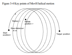
For Helical motion, the transition and WaitFinish are not supported.
Example:

3.2 Control commands
The list of control commands:
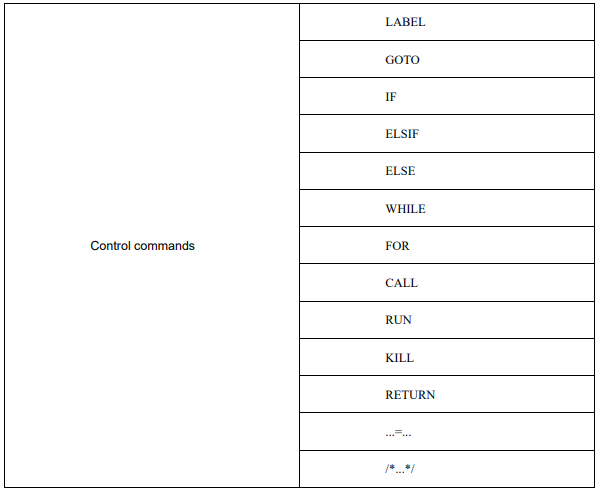
LABEL
Label command is used to define the GOTO jump target.
Example:

GOTO
GOTO command is used to jump to different parts of the program. The jump target is defined by the LABEL. It is not allowed to jump into the WHILE loop program block or the IF program block from outside.
Example:

IF
IF command is used for jump control of the conditional judgment expression. When the result of the conditional judgment expression is TRUE, the program executes the block content under IF. Every IF command must be followed by the keyword ENDIF to mark the end of the conditional statement block.
Example:

ELSIF
ELSIF relies upon the IF command. It follows closely the IF command block. When the IF logic is not established, the ELSIF logic judgment is performed.
The way to set the ELSIF expression is the same as that of the IF expression.

ELSE
The ELSE command is used in conjunction with the IF command to specify the statements to be executed when the condition of the IF statement is not satisfied.
Example:

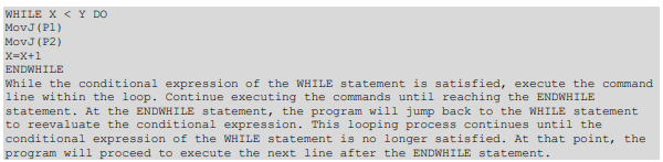
WHILE
WHILE command executes sub-statements in loops when the conditions are met. The loop control for this command must be terminated using the keyword ENDWHILE.
Example:
FOR
The FOR command is used to loop and execute a substatement while a condition is satisfied. This command must be terminated using the keyword ENDFOR as the loop control end. The FOR command consists of three segments separated by commas and has the following format:
FOR INT0.value = 0, INT0.value < 10, INT0.value = INT0.value + 1 DO
…
ENDFOR
The first segment of characters initializes the assignment. The second segment of characters is the loop condition. If the condition is satisfied, the content within the FOR loop is executed. If the condition is not satisfied, the program exits the FOR loop. The third segment consists of periodic execution statements that are executed once at the end of each iteration of the FOR loop
Example:

CALL
The CALL program command. The current program jumps to another subroutine in the same project, which then jumps back to the current program after execution.
For example, CALL B in program A, CALL C in B, CALL D in C, and CALL E in D
Example:

RUN
The program parallel running command. It enables the robot to run other programs while running the current program (programs must be in the same project), which means a new thread will be started to execute the other program while the current program continues to run normally.
Note: The current system supports running up to eight concurrent programs (excluding the main running program), and the RUN programs should not include motion-related commands.
Example:

KILL
To stop the commands running in parallel. This command is used to terminate programs launched by the RUN command.
Example:

RETURN
The Return command. After executing this command, the program will jump to the end of the program, to effectively terminate the current program.
Example:

...=...
Establish an expression to assign a value to a variable.
Example:

/*…*/
COMMENT command, to add definitions or remarks to the program.
This command will not affect the operation of the program, but only for reading and understanding the program.
Example:

3.3 WAIT commands
List of WAIT commands:

Wait
It is used to set the robot wait time in ms, either as an int constant or as an INT variable.
Example:

WaitFinish
It is used to control the execution of the program during the robots motion, and can be set to execute the next line of command when a certain percentage of the motion is executed.
Example:

WaitCondition
Set the conditions for the robot to execute the WAIT. If the condition is satisfied, the next command is executed. If the condition is not satisfied within the set time, it returns to the timeout state and continues with the next command.
WaitConditionCTIETV [Goto]
C: Judgement condition (Condition)
Meaning: Conditional Expression: Execute the next instruction only when the condition is true; otherwise, the program will continue to wait until the condition becomes true.
T: Duration (Time)
Data type: int or INT variable, with a value of a positive integer or 0.
Meaning: Represents the time duration required for waiting, measured in milliseconds (ms). If the value of this parameter is 0, the program will wait until the condition is true before proceeding to execute the next command. If the value is not 0, even if the condition is still not true, the system will skip this command after waiting for the specified duration and continue executing the subsequent command.
IE: Interrupt enabling (Interrupt enable)
Data type: 0 or 1
Meaning: Set whether or not to continue timing after the program resumes during the waiting process.
0: Stop timing when the program stops, and continue timing before the program stopped when being resumed.
1: When the program stops, stop timing, and continue timing when being resumed.
TV: Timeout judgment value (Timeout Value)
Data type: INT variable.
Meaning: If the input condition is TRUE and the command is executed, assign a value of 0 to the variable;When the command is executed due to timeout, assign 1 to the variable.
[Goto]: Tag name for timeout jump (Label name)
Data type: label
Meaning: The name of the label, which should correspond to a LABEL command that has been taught in the currently loaded program, such as "Start." After a timeout, the program pointer will jump to the corresponding
command line associated with the specified label name.
Note: This parameter is optional and defaults to "No Jump".
Example:

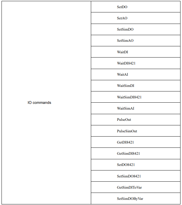
3.4 IO commands
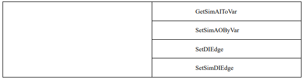
The list of IO commands:
SetDO
This command is used to set a digital output port to the TRUE (1) or FALSE (0) state.
The command parameters are described as below:
SetDO DOUT VALUE
DOUT: Digital Output variable (Target DO Port)
Data type: DO variable type
Meaning: The digital output port variable to be set.
VALUE: Target value (Value)
Data type: int
Meaning: The value of the digital output port to be set, either 0 or 1 can be entered, representing the low or high level of the port respectively.
For example 1:

SetAO
Set the analog output port to a certain value.
The command parameters are described as below:
SetAOAOUT VALUE
AOUT: Analog output variable (Target AO Port)
Data type: AO variable type
Meaning: The analog output port variable to be set.
VALUE: Target value (Value)
Data type: real
Meaning: The value to set for the analog output port. It can be in the range of -10.0 to 10.0, representing the output level of the port.
For example 1:

SetSimDO
Set the virtual digital output port to TRUE (1) or FALSE (0)
SetSimDOSIMDOUT VALUE
SIMDOUT: Virtual digital output variable (Target SimDO Port)
Data type: SimDO variable type
Meaning: The virtual digital output port variable to be set.
VALUE: Target value (Value)
Data type: int
Meaning: The value to set for the virtual digital output port. It can be either 0 or 1, representing the state of the port.
For example 1:

SetSimAO
Set the virtual analog output port to a certain value.
The command parameters are described as below:
SetSimAOSIMAOUT VALUE
SIMAOUT: Virtual analog output variable (Target SimAO Port)
Data type: SimAO variable type
Meaning: The virtual analog output port variable to be set.
VALUE: Target value (Value)
Data type: real
Meaning: The value to set for the virtual analog output port. It can be in the range of -10.0 to 10.0, representing the output value of the port.
Example 1:

WaitDI
This command is used to wait for a digital input port to be set (1) or reset (0) within a specified duration. If the condition is met within the set duration, the program continues executing. If the condition is not met within the set duration, the Timeout judgment value is set to 1, and the program continues executing.
Explanation of the command parameters:
WaitDIDIN VALUE T INTERENABLE RET [Goto]
DIN: Digital input variable (Target DI Port)
Data type: DI variable type
Meaning: The digital input variable used for the wait condition evaluation.
VALUE: Target value (Value)
Data type: int
Meaning: When the value of the digital input variable matches the Target value, it is considered as the condition being met, and the program can continue executing.
T: Duration (Time)
Data type: int or INT variable
Meaning: The duration for waiting for a specific DI signal. This parameter specifies the duration in milliseconds (ms). When the value is 0, it forces the program to wait until the DI signal is satisfied before considering it a successful execution.
INTERENABLE: Interrupt enabling (Interrupt Enable)
Data type: int
Meaning: This parameter determines whether the timer restarts when the program is halted and resumed during the waiting process.
− 0: Stop timing when the program stops, and continue timing before the program stopped when being resumed.
− 1: When the program stops, stop timing, and continue timing when being resumed.
RET: Timeout judgment value (Timeout Flag)
Data type: INT
Meaning: Return to the state after the command is executed
− 0: Signal is detected successfully
− 1: No signal is detected, and the command times out and returns.
[Goto]: Tag name for timeout jump (Label name)
Data type: label
Meaning: The name of the label, which should correspond to a LABEL command that has been taught in the currently loaded program, such as "Start." After a timeout, the program pointer will jump to the instruction line corresponding to the specified label name.
Note: This parameter is optional and defaults to "No Jump".
Example 1:

WaitAI
This command is used to wait for an analog input port to have a value equal to the specified value within a specified duration. If the condition is met within the set duration, the program continues executing. If the condition is not met within the set duration, the Timeout judgment value is set to 1, and the program continues executing.
The command parameters are described as below:
WaitAIAIN VALUE T INTERENABLE RET [Goto]
AIN: Analog input variable (Target AI Port)
Data type: AI variable type
Meaning: The analog input variable used for the wait condition evaluation.
VALUE: Target value (Value)
Data type: real.
Meaning: When the value of the analog input variable matches the target value, it is considered as satisfying the wait condition, and the program can continue executing.
T: Duration (Time)
Data type: int or INT variable
Meaning: The duration for waiting for a specific AI signal, specified in milliseconds (ms). If the value is 0, it forces the program to wait until the AI signal satisfies the condition before considering it a successful execution.
INTERENABLE: Interrupt enabling (Interrupt Enable)
Data type: int
Meaning: This parameter determines whether the timer restarts when the program is halted and resumed during the wait process.
− 0: Stop timing when the program stops, and continue timing before the program stopped when being resumed.
− 1: When the program stops, stop timing, and continue timing when being resumed.
RET: Timeout judgment value (Timeout Flag)
Data type: INT
Meaning: To return the status after the execution of this command.
− 0: Signal is detected successfully
− 1: No signal is detected, and the command times out and returns.
[Goto]: Label name for timeout jump (Label name)
Data type: label
Meaning: The label name to jump to after a timeout occurs. This label should correspond to a LABEL command that has been taught in the currently loaded program. When a timeout occurs, the program pointer will jump to the command line associated with the specified label name.
Note: This parameter is optional and defaults to "No Jump".
Example 1:

WaitSimDI
The command is used to wait for a virtual digital input port to match a given value within a specified duration. If the
condition is met within the set duration, the program will continue execution. If the condition is not met within the set
duration, the Timeout judgment value will be set to 1, and the program will continue execution.
The command parameters are described as below:
WaitSimDISIMDIN VALUE T INTERENABLE RET [Goto]
SIMDIN: Virtual digital input variable (Target SimDI Port)
Data type: SimDI variable type
Meaning: The virtual digital input variable used for the wait condition evaluation.
VALUE: Target value (Value)
Data type: int
Meaning: When the value of the virtual digital input variable matches the Target value, the condition is
considered met, and the program continues execution.
T: Duration (Time)
Data type: int or INT variable
Meaning: The waiting duration, which is used to specify the duration for waiting a specific SimDI signal,
measured in milliseconds. When the value is 0, it forces the program to wait until the DI signal is satisfied
before considering it a successful execution.
INTERENABLE: Interrupt enabling (Interrupt Enable)
Data type: int
Meaning: The parameter is used to set whether or not to restart timing after restarting if the program is halted when waiting.
− 0: Stop timing when the program stops, and continue timing before the program stopped when being resumed.
− 1: When the program stops, stop timing, and continue timing when being resumed.
RET: Timeout judgment value (Timeout Flag)
Data type: INT
Meaning: To return the status after the command execution is done.
− 0: Signal is detected successfully
− 1: No signal is detected, and the command times out and returns.
[Goto]: Tag name for timeout jump (Label name)
Data type: label
Meaning: The label name to jump to after a timeout occurs. This label should correspond to a LABEL command that has been taught in the currently loaded program, such as "Start". When a timeout occurs, the program pointer will jump to the command line associated with the specified label name.
Note: This parameter is optional and defaults to "No Jump".
Example 1:

This command is used to wait for the virtual analog input variable to be equal to a given value within a specified duration. If the condition is met within the set duration, the program continues executing; otherwise, the timeout judgment value is set to 1, and the program continues executing.
The command parameters are described as below:
WaitSimAISIMAIN VALUE T INTERENABLE RET [Goto]
SIMAIN: Virtual analog input variable (Target SimAI Port)
Data type: SimAI variable type
Meaning: The virtual analog input variable for the wait condition evaluation.
VALUE: Target value (Value)
Data type: real
Meaning: When the value of the virtual analog input variable is equal to the target value, it is considered as satisfying the wait condition, and the program can proceed to the next step.
T: Duration (Time)
Data type: int or INT variable
Meaning: The waiting duration, which is used to specify the duration for waiting a specific SimDI signal, measured in milliseconds. When the value is 0, it forces the program to wait until the DI signal is satisfied before considering it a successful execution.
INTERENABLE: Interrupt enabling (Interrupt Enable)
Data type: int
Meaning: The parameter is used to set whether or not to restart timing after restarting if the program is halted when waiting.
− 0: Stop timing when the program stops, and continue timing before the program stopped when being resumed.
− 1: When the program stops, stop timing, and continue timing when being resumed.
RET: Timeout judgment value (Timeout Flag)
Data type: INT
Meaning: To return the status after the command execution is done.
− 0: Signal is detected successfully
− 1: No signal is detected, and the command times out and returns.
[Goto]: The label name for timeout jump (Label name)
Data type: label
Meaning: The label name to jump to after a timeout occurs. This label should correspond to a LABEL command that has been taught in the currently loaded program, such as "Start". When a timeout occurs, the program pointer will jump to the command line associated with the specified label name.
Note: This parameter is optional and defaults to “No Jump”.
Example 1:

WaitDI8421
The command is used to wait for a specific combination of states in a group of consecutive digital input (DI) ports within a specified duration. If the condition is met within the set duration, the program will proceed to the next step.
If the condition is not met within the set duration, the timeout judgment value will be set to 1, and the program will continue executing the subsequent steps.
The command parameters are described as below:
WaitDI8421 BEGINPORT ENDPORT VALUE T INTERENABLE RET [Goto]
BEGINPORT: The beginning DI port (Begin Port)
Data type: int
Meaning: The beginning port number of the consecutive DI ports in the segment.
ENDPORT: The ending DI port (End Port)
Data type: int
Meaning: The ending port number of the consecutive DI ports in the segment.
VALUE: Target value (Value)
Data type: int
Meaning: To convert the value of the consecutive DI port segment into a decimal number. If it is equal to the target value (VALUE), it is considered to meet the condition.
T: Duration (Time)
Data type: int or INT variable
Meaning: The duration in milliseconds to wait for the digital input (DI) signal in this group. When the value is 0, it will forcefully wait until the DI signal satisfies the condition before considering it as a successful execution.
INTERENABLE: Interrupt enabling (Interrupt Enable)
Data type: int
Meaning: This parameter is used to determine whether the timing restarts if the program is halted and resumed during the waiting process.
− 0: Stop timing when the program stops, and continue timing before the program stopped when being resumed.
− 1: When the program stops, stop timing, and continue timing when being resumed.
RET: Timeout judgment value (Timeout Flag)
Data type: INT
Meaning: To return the status after the command execution is done.
− 0: Signal is detected successfully
− 1: No signal is detected, and the command times out and returns.
[Goto]: Tag name for timeout jump (Label name)
Data type: label
Meaning: The label name to jump to after a timeout occurs. This label should correspond to a LABEL command that has been taught in the currently loaded program, such as "Start". When a timeout occurs, the program pointer will jump to the command line associated with the specified label name.
Note: This parameter is optional and defaults to “No Jump”.
Example 1:

WaitSimDI8421
This command is used to wait for a specified duration for a group of consecutive virtual digital input (SimDI) ports to satisfy a specific state combination. If the condition is met within the set duration, the program will continue execution. If the condition is not met within the set duration, the timeout judgment value will be set to 1, and the program will continue execution.
The command parameters are described as below:
WaitSimDI8421 BEGINPORT ENDPORT VALUE T INTERENABLE RET [Goto]
BEGINPORT: The beginning SimDI port (Begin Port)
Data type: int
Meaning: The beginning port number of the consecutive SimDI ports in the segment.
ENDPORT: The ending SimDI port (End Port)
Data type: int
Meaning: The ending port number of the consecutive SimDI ports in the segment.
VALUE: Target value (Value)
Data type: int
Meaning: To convert the value of the consecutive SimDI port segment into a decimal number. If it is equal to the target value (VALUE), it is considered to meet the condition.
T: Duration (Time)
Data type: int or INT variable
Meaning: The duration in milliseconds to wait for the digital input (SimDI) signal in this group. When the value is 0, it will forcefully wait until the DI signal satisfies the condition before considering it as a successful execution.
INTERENABLE: Interrupt enabling (Interrupt Enable)
Data type: int
Meaning: This parameter is used to determine whether the timing restarts if the program is halted and resumed during the waiting process.
− 0: Stop timing when the program stops, and continue timing before the program stopped when being resumed.
− 1: When the program stops, stop timing, and continue timing when being resumed.
RET: Timeout judgment value (Timeout Flag)
Data type: INT
Meaning: To return the status after the command execution is done.
− 0: Signal is detected successfully
− 1: No signal is detected, and the command times out and returns.
[Goto]: Tag name for timeout jump (Label name)
Data type: label
Meaning: The label name to jump to after a timeout occurs. This label should correspond to a LABEL command that has been taught in the currently loaded program, such as "Start". When a timeout occurs, the program pointer will jump to the command line associated with the specified label name.
Note: This parameter is optional and defaults to “No Jump”.
For example1:

PulseOut
This command is used to generate a pulse with a specified duration and state at a specific digital output port.
The command parameters are described as below:
PulseOutDOUT VALUE T INTERENABLE
DOUT: Digital output variable (Target DO Port)
Data type: DO variable type
Meaning: To specify the digital output port of the output pulse.
VALUE: Target value (Value)
Data type: int
Meaning: The state of the pulse to be output at the specified digital output port.
T: Duration (Time)
Data type: int
Meaning: The duration for which the pulse signal will be maintained
INTERENABLE: Interrupt enabling (Interrupt Enable)
Data type: int
Meaning: This parameter determines whether the port continues to output the pulse signal if the program is halted during the pulse output process.
− 0: When the program is stopped, the pulse output will continue for the set time and then stop. Its function will not be affected by the program stopping.
− 1: When both the program and output are stopped, the output will continue when the program continues to run, which means that it is synchronized with the program running state. The output acts based on the state of the program.
For example1:

PulseSimOut
This command is used to generate a pulse with a specified duration and state at a specific virtual digital output port.
The command parameters are described as below:
PulseOutSIMDOUT VALUE T INTERENABLE
SIMDOUT: Virtual digital output variable (TargetSim DO Port)
Data type: SimDO variable type
Meaning: To specify the virtual digital output port of the output pulse.
VALUE: Target value (Value)
Data type: int
Meaning: The state of the pulse to be output at the specified virtual digital output port.
T: Duration (Time)
Data type: int
Meaning: The duration for which the pulse signal will be maintained
INTERENABLE: Interrupt enabling (Interrupt Enable)
Data type: int
Meaning: This parameter determines whether the port continues to output the pulse signal if the program is halted during the pulse output process.
− 0: When the program is stopped, the pulse output will continue for the set time and then stop. Its function will not be affected by the program stopping.
− 1: When both the program and output are stopped, the output will continue when the program continues to run, which means that it is synchronized with the program running state. The output acts based on the state of the program.
For example1:

GetDI8421
This command is used to get the status of a consecutive digital input DI port, (regard it as a segment of binary data) and return it as a decimal number.
The command parameters are described as below:
GetDI8421BEGINPORT ENDPORT RETURNVALUE
BEGINPORT: The beginning DI port (Begin Port)
Data type: int
Meaning: The beginning port number of the consecutive DI ports in the segment.
ENDPORT: The ending DI port (End Port)
Data type: int
Meaning: The ending port number of the consecutive DI ports in the segment.
RETURNVALUE: Returned value (Return Value)
Data type: INT
Meaning: To treat the consecutive DI ports as a binary number, convert it to a decimal value and return the decimal number.
For example1:

GetSimDI8421
This command is used to get the status of a consecutive digital input SimDI port, (regard it as a segment of binary data) and return it as a decimal number.
The command parameters are described as below:
GetSimDI8421BEGINPORT ENDPORT RETURNVALUE
BEGINPORT: The beginning SimDI port (Begin Port)
Data type: int
Meaning: The beginning port number of the consecutive SimDI ports in the segment.
ENDPORT: The ending SimDI port (End Port)
Data type: int
Meaning: The ending port number of the consecutive SimDI ports in the segment.
RETURNVALUE: Returned value (Return Value)
Data type: INT
Meaning: To treat the consecutive SimDI ports as a binary number, convert it to a decimal value and return the decimal number.
For example1:

SetDO8421
Set a segment of continuous DO port status (regard it as a segment of binary data); convert the decimal number transmitted in into a binary number, and set it to the designated DO port.
The command parameters are described as below:
SetDO8421BEGINPORT ENDPORT SETVALUE
BEGINPORT: Start DO port (Begin Port)
Data type: int
Meaning: The beginning port number of the consecutive DO ports in the segment.
ENDPORT: End DO port (End Port)
Data type: int
Meaning: The ending port number of the consecutive DO ports in the segment.
SETVALUE: Set Value
Data type: int
Meaning: To convert the decimal number into a binary number and set it to the specified consecutive DO ports in the segment.
For example1:

SetSimDO8421
This command is used to set the state of a consecutive range of SimDO ports (regard them as a segment of binary data). It converts the incoming decimal number into a binary number and sets it to the specified SimDO ports.
The command parameters are described as below:
SetSimDO8421BEGINPORT ENDPORT SETVALUE
BEGINPORT: Start SimDO port (Begin Port)
Data type: int
Meaning: The beginning port number of the consecutive SimDO ports in the segment.
ENDPORT: End SimDO port (End Port)
Data type: int
Meaning: The ending port number of the consecutive SimDO ports in the segment.
SETVALUE: Set Value
Data type: int
Meaning: To convert the decimal number into a binary number and set it to the specified consecutive SimDO ports in the segment.
For example1:

GetSimDIToVar
Map the virtual digital input signal to a variable.
The command parameters are described as below:
GetSimDITOVarSIMDIN VAR
SIMDIN: Virtual digital input port variable (SimDI Port)
Data type: SimDI variable type
Meaning: To retrieve the status of the virtual digital input port and assigns it as the value to the target variable.
VAR: Target variable (Target Variable)
Data type: BOOL
Meaning: To accept the value retrieved from the simulated digital input port.
For example1:

SetSimDOByVar
Map the value of a Boolean variable to a digital output variable.
The command parameters are described as below:
SetSimDOByVarSIMDOUT VAR
SIMDOUT: Virtual digital output port variable (SimDO Port)
Data type: SimDO variable type
Meaning: To output the acquired variable value on the SimDO port to which the variable is bound.
VAR: Variable
Data type: BOOL
Meaning: To get the value of this variable and output it to the specified virtual digital output port.
Example 1:

GetSimAIToVar
This command is used to map a virtual analog input signal to a variable.
The command parameters are described as below:
GetSimAIToVarSIMAIN VAR
SIMAIN: Virtual analog input port variable (Sim AI Port)
Data type: SimAI variable type
Meaning: To get the state of the virtual analog input port at this end as the value to be assigned to the target variable.
VAR: Target variable
Data type: REAL
Meaning: To accept the value of the virtual analog input port on the acquisition end.
For example1:

SetSimAOByVar
This command maps the value of a REAL variable to a virtual analog output variable.
The command parameters are described as below:
SetSimAOByVarSIMAOUT VAR
SIMAOUT: Virtual analog output port variable (Sim AO Port)
Data type: SimAI variable type
Meaning: The virtual analog output port to be set and output.
VAR: variable
Data type: REAL
Meaning: To get the value of this variable and output it to the specified virtual analog output port.
For example1:

SetDIEdge
Set the edge signal state of a virtual digital input port forcibly by using the commands.
The command parameters are described as below:
SetDIEdgeDIN EDGETYPE VALUE
DIN: Digital input port variable (Target DI Port)
Data type: DI variable type
Meaning: The digital input variable for the edge signal to be forced.
EDGETYPE: Edge type (Edge Type)
Data type: enum
Meaning: To select the edge type to be forced on a given port.
VALUE: Force Value
Data type: int
Meaning: The value of the edge signal to be forced at a given port.
For example1:

SetSimDIEdge
Set the edge signal state of a virtual digital input port forcibly by using the commands.
The command parameters are described as below:
SetDIEdgeSIMDIN EDGETYPE VALUE
SIMDIN: Vrtual digital input port variable (Target SimDI Port)
Data type: SimDI variable type
Meaning: The virtual digital input variable for the edge signal to be forced.
EDGETYPE: Edge type (Edge Type)
Data type: enum
Meaning: The virtual digital input variable for the edge signal to be forced.
VALUE: Force Value
Data type: int
Meaning: The value of the edge signal to be forced at a given port.
For example1:

3.5 SET commands
The list of SET commands:
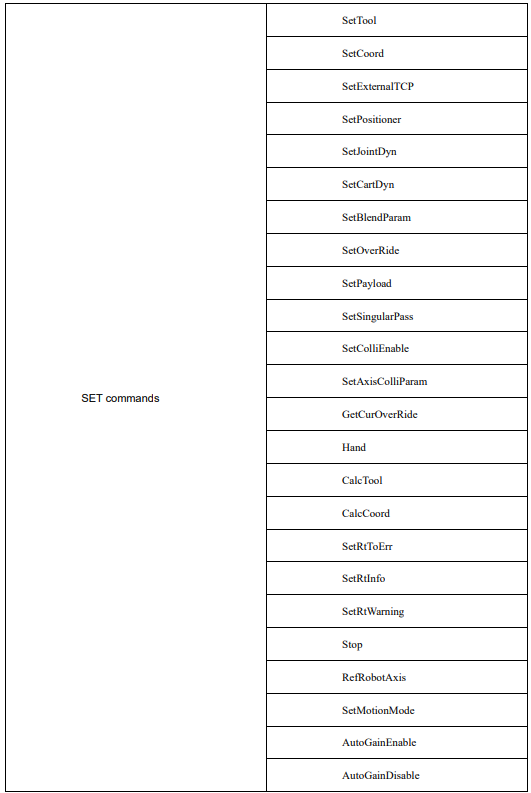
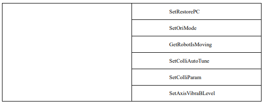
SetTool
This command is used to select the Tool Parameters. The command parameters are described as below:
SetTool Tool
Tool: Tool Parameters (Tool Param)
Data type: TOOL variable
Meaning: The selected tool parameters
For example:

SetCoord
Select the command of User Coordinates. The command parameters are described as below:
SetCoordCoord
Coord: User Coordinate System parameters (UserCoord Param)
Data type: USERCOORD variable
Meaning: The selected parameters for User Coordinate System
For example:

SetExternalTCP
This command is used to select the external tool coordinate system (TCP). The command parameters are described as below:
SetExternalTCPExtTCP
ExtTCP: External TCP parameters (ExternalTCP Param)
Data type: EXTTCP variable
Meaning: The selected external TCP parameters
For example:

SetPositioner
It is used to set the reference coordinates of the system to POSITIONER coordinates. After command execution, the system will switch the reference coordinates to the POSITIONER coordinates. The robot will then move relative to the POSITIONER coordinates. The command parameters are described as below:
SetPositioner Positioner
Positioner: Positioner Coordinate System Parameters (Positioner Param)
Data type: POSITIONER variable
Meaning: The selected parameters of Positioner Coordinate System
For example:

SetJointDyn
It is used to set dynamic joint parameters. After running the command, the subsequent motion commands will all run using such dynamic parameters. The command parameters are described as below:
SetJointDynAcc Dec Jerk Torq
Acc: Acceleration (%) (Acc(%) )
Data type: int
Meaning: The percentage of the maximum acceleration of the joint, with the value ranged from 1 to 100.
Dec: Deceleration (%) (Dec(%) )
Data type: int
Meaning: The percentage of joint maximum deceleration, with the value ranged from 1 to 100.
Jerk: Jerk (Jerk(%) )
Data type: int
Meaning: The percentage of the maximum jerk of the joint, with the value ranged from 1 to 100.
Torq: Torque (Torq(%) )
Data type: int
Meaning: The percentage of the maximum torque of the joint, with the value ranged from 1 to 100.
For example:

SetCartDyn
Set the dynamic parameters in Cartesian space. After running this command, the subsequent motion commands will run using this dynamic parameter. The command parameters are described as below:
SetCartDynAcc Dec Jerk OriAcc OriDec OriJerk Torq
Acc: Acceleration (%) (Acc(%) )
Data type: int
Meaning: The percentage of maximum acceleration for linear and circular motion, with the value ranged from 1 to 100.
Dec: Deceleration (%) (Dec(%) )
Data type: int
Meaning: The percentage of maximum deceleration for linear and circular motion, with the value ranged from
1 to 100.
Jerk: Jerk (Jerk(%) )
Data type: int
Meaning: The percentage of maximum acceleration jerk for linear and circular motion, with the value ranged from 1 to 100.
OriAcc: Posture Acceleration (%) (OriAcc(%) )
Data type: int
Meaning: The percentage of the maximum rotating acceleration of the posture, with the value ranged from 1 to 100.
OriDec: Posture Deceleration (%) (OriDec(%) )
Data type: int
Meaning: The percentage of the maximum rotating deceleration of the posture, with the value ranged from 1 to 100.
OriJerk: Posture Jerk (OriJerk(%) )
Data type: int
Meaning: The percentage of the maximum rotating jerk of the posture, with the value ranged from 1 to 100.
Torq: Torque (Torq(%) )
Data type: int
Meaning: The percentage of the maximum torque of the joint, with the value ranged from 1 to 100.
For example:

SetBlendParam
It is used to set the transition parameters. After running this command, subsequent motion commands are run with this transition parameter. The command parameters are detailed below:
SetBlendParamB C
B: Transition type (BlendType)
Data type: enum (FINE/RELATIVE/DEFAULT)
Meaning: The way of transition when the robot approaches the endpoint.
− FINE: No transition.
− RELATIVE: Relative transition.
− ABSOLUTE: Absolute transition.
C: Transition Value (BlendValue)
Data type: ZONE
Meaning: The transition value when the robot approaches the endpoint.
Note: This parameter is optional and defaults to C100.
For example:

SetOverRide
This command is used to set the Global Speed. After executing this command, all subsequent motion commands will be executed at this speed. The command parameters are described as below:
SetOverRidevf
vf: Global speed (%) (speed factor(%)
Data type: int or INT variable
Meaning: The percentage of Global Ppeed, with the value ranged from 1 to 100.
For example:

SetPayload
This command is used to set the payload of the workpiece. The command parameters are described as below:
SetPayloadpl
pl: Payload
Data type: PAYLOAD variable
Meaning: The workpiece load parameter, which stores a series of relevant parameters such as PAYLOAD command.
For example:

SetSingularPass
The command to set the cross-wrist singularity function switch can be selected as "OPEN" or "CLOSE".
SetSingularPass SingularPass
SingularPass: Cross-wrist Singularity (SingularPass)
Data type: enum (OPEN/CLOSE)
Meaning: Whether the wrist singularity is performed?
− OPEN: to open.
− CLOSE: To close.
For example: 
SetColliEnable
A command to set the collision detection enable.
SetColliEnableAxisIDValid
AxisID: Axis ID
Data type: enum (GROUP/A1/A2/A3/A4/A5/A6)
Meaning: The axis ID for setting collision enable.
− GROUP: All axes.
− A1: Axis 1.
− A2: Axis 2.
− A3: Axis 3.
− A4: Axis 4.
− A5: Axis 5.
− A6: Axis 6.
Valid: Valid
Data type: enum (ENABLE/DISABLE)
Meaning: Determine if it is valid.
− ENABLE: Valid.
− DISABLE: Invalid.
For example:

SetAxisColliParam
A command used to set the collision detection sensitivity value.
SetAxisColliParamAxisIDValue
AxisID: Axis ID
Data type: enum (A1/A2/A3/A4/A5/A6)
Meaning: The axis ID for setting collision parameters.
− A1: Axis 1.
− A2: Axis 2.
− A3: Axis 3.
− A4: Axis 4.
− A5: Axis 5.
− A6: Axis 6.
Value: Sensitivity value (Value)
Data type: Constant
Meaning: The sensitivity to collision.
For example:

GetCurOverRide
Get the current override. When this command is executed, the Global Speed value retrieved will be stored in the incoming variable. The command parameters are described as below:
GetCurOverRideV
V: Global Speed (%) (speed factor(%)
Data type: INT variable
Meaning: To store the Global Speed percentage read from the system for other uses.
For example:

GetCurOverRide
Get the current override. When this command is executed, the Global Speed value retrieved will be stored in the incoming variable. The command parameters are described as below:
GetCurOverRideV
V: Global Speed (%) (speed factor(%)
Data type: INT variable
Meaning: To store the Global Speed percentage read from the system for other uses.
For example:

Hand
Set the lefty and righty system. It is only applicable to SCARA models. The command parameters are described as below:
Handst
st: left-right hand setting type (set type)
Data type: enum (Lefty/Righty/Default)
Meaning: To set the robots left -right hand type mode.
− Lefty: To set the left hand.
− Righty: To set the right hand.
− Default: To set to the default mode.
For example:

CalcTool
It calculates the tool parameters according to the four "calibration points". The command parameters are described as below:
CalcToolP1 P2 P3 P4 Tool
P1: Calibration point 1 (the first position)
Data type: CPOS
Meaning: The 1st calibration point.
P2: Calibration point 2 (the second position)
Data type: CPOS
Meaning: The 2nd calibration point.
P3: Calibration point 3 (the third position)
Data type: CPOS
Meaning: The 3rd calibration point.
P4: Calibration point 4 (the forth position)
Data type: CPOS
Meaning: The 4th calibration point.
Tool: Tool Parameters (Tool Param)
Data type: TOOL
Meaning: The tool parameters as calibrated are calculated.
For example:

CalcCoord
This command calculates the parameters for calibration of user coordinate system based on the three points so provided. The command parameters are described as below:
CalcCoordP1 P2 P3 Coord
P1: The original position
Data type: CPOS
Meaning: The 1st calibration point, also the origin of the user coordinate system.
P2: Calibration point in RX direction (the second position)
Data type: CPOS
Meaning: The 2nd calibration point, also the calibration point in the RX direction of the user coordinate system.
P3: RXRY plane calibration points (the third position)
Data type: CPOS
Meaning: The 3rd calibration point, also the RXRY plane calibration point of the user coordinate system.
Coord: User parameters (UserCoord Param)
Data type: USERCOORD
Meaning: The parameter of user coordinate system as calibrated are calculated.
For example:

SetRtToErr
Enable the robot to stop running and issue an error message. The command parameters are described as below:
SetRtToErrmsg errId
msg: Error message (errInfo)
Data type: str
Meaning: Set the error message.
errId: Error number (errId)
Data type: int
Meaning: To set the error number, with value ranging from 90001 to 100000.
For example:

SetRtInfo
This command is used to set a reminder information but does not affect the running of the program. The command parameters are described as below:
SetRtInfo msg errId
msg: Remainder message (errInfo)
Data type: str
Meaning: The reminder message as set.
errId: Reminder ID (errId)
Data type: int
Meaning: The reminder ID as set, with the value ranging from 70001 to 80000.
For example:

SetRtWarning
Set the warning message but does not affect the robot operation. The command parameters are described as below:
SetRtWarning msg errId
msg: Warning message (errInfo)
Data type: str
Meaning: The warning message as set.
errId: Warning ID (errId)
Data type: int
Meaning: The warning ID as set, with the value ranging from 80001 to 90000.
For example:

Stop
Stop the execution of all the activated programs, and stop the robots movement simultaneously.
For example:

RefRobotAxis
Calibrate the zero return position and run in single step. The command parameters are described as
below:
RefRobotAxisnum
num: Axis number
Data type: int
Meaning: The axis number of joint, with the value ranging from 1 to 16.
For example:

SetMotionMode
This command is used to set the robot motion mode. The command parameters are described as below:
SetMotionMode MotionMode
MotionMode: Motion mode (Mode)
Data type: enum (STANDARD/LOW_OSCILLATION)
Meaning: To set the robots motion mode
− STANDARD: Standard mode.
− LOW_OSCILLATION: The low oscillation mode.
For example:

AutoGainEnable
The command to enable servo Auto Tune. After executing this command, the system will optimize the subsequent motion commands at low speed according to the incoming LsScale and LsThresh parameters. For details on how to use this command, refer to the command parameters described as below:
AutoGainEnableLsScaleP LsThreshP
LsScaleP: Low-speed segment gain ratio (LsScale)
Data type: LsScale type variable
Meaning: To set the low-speed segment gain ratio threshold for each joint axis of the robot.
LsThreshP: Low-speed segment speed threshold (LsThresh)
Data type: LsThresh type variable
Meaning: To set the low-speed segment speed threshold for each joint axis of the robot.
For example:

AutoGainDisable
Disable servo parameter gain command. After executing this command, the system will deactivate the optimized processing of low-speed segments for motion commands.
For example:

AutoGainDisable
Disable servo parameter gain command. After executing this command, the system will deactivate the optimized processing of low-speed segments for motion commands.
For example:

SetRestorePC
This command sets the pc pointer when the run program goes from Halt/Stop to run. Please note that this command is only valid for use in run programs. The command parameters are detailed as below:
SetRestorePCindex
index: Program pointer (PC index)
Data type: int
Meaning: run 程序恢复运行时的行号.
For example:

SetOriMode
The orientation mode setting command, which enables interpolation in a certain pose mode when the robot executes a motion path. The command parameters are described as below:
SetOriMode OriMode
OriMode: Orientation Mode (orientation Mode)
Data type: enum(CirMidPassOpen/CirMidPassClose)
Meaning: To set the orientation mode of the current path.
− CirMidPassOpen: Enable the interpolation of arcs passing through intermediate auxiliary points to optimize the problem of having to split the full circle into 3-4 arcs in order to guarantee the weld orientation.
− CirMidPassClose: Disable the interpolation of arcs passing through intermediate auxiliary points.
For example:

GetRobotIsMoving
It is used to get the current robot motion status. The command parameters are described as below:
GetRobotIsMoving MovStatus
MovStatus: Robot Moving Status)
Data type: BOOL variable
Meaning: To store the current motion state of the robot. True is for the motion state, and False is for the nonmotion state.
For example:

SetColliAutoTune
The following command is used to configure the Auto Tune feature for collision detection. When the Auto Tune stage for collision detection parameters is set to Start, Pause, Continue, or End, the data recording status for the Auto Tune feature will be configured accordingly. When the Auto Tune stage for collision detection parameters is set to CalCulate, the collision Auto Tune parameters will be calculated based on the data recorded by the Auto Tune feature.
The command parameters are described as below:
SetColliAutoTune cmdType method level colliId
cmdType: Collision detection parameter Auto Tune stage (Colli cmd Type)
Data type: enum (Start/Pause/Continue/End/Calculate)
Meaning: Data recording status for the Auto Tune feature.
− Start: To restart.
− Pause: To pause.
− Continue: To continue.
− End: To end.
− Calculate: To calculate and generate.
method: Calculate and generate.
Data type: enum (Default/ Default +/ Default ++/)
Meaning: Collision detection method used for Auto Tune.
− Default: Default.
− Default +: Strong.
− Default ++: Stronger.
Note: This parameter is only valid when the collision detection parameter Auto Tune stage is set to Calculate.
level: Sensitivity (level)
Data type: enum (Highest/High/Default/Low/Lowest)
Meaning: Sensitivity level of the Auto Tune results.
− Highest
− High
− Default
− Low
− Lowest
Note: This parameter is only valid when the collision detection parameter Auto Tune stage is set to Calculate.
colliId: Collision parameter (Colli id)
Data type: COLLIPARAM variable
Meaning: To store the collision parameters resulting from Auto Tune calculations.
Note: This parameter is only valid when the collision detection parameter Auto Tune stage is set to Calculate.
SetColliParam
This command is used to set the collision detection parameters. Refer to the command parameters described as below:
SetColliParam colliId AxisID Valid Value
colliId: Collision parameter (Colli id)
Data type: COLLIPARAM variable
Meaning: The parameter used by the collision detection function. This parameter is optional and defaults to DEFAULT (factory default) .
AxisID: Axis number (AxisID)
Data type: enum (DEFAULT/GROUP/A1/A2/A3/A4/A5/A6)
Meaning: The axis number for which the collision detection validity and sensitivity values need to be set.
− DEFAULT: meaningless.
− GROUP: All axes
− A1: Axis 1.
− A2: Axis 2.
− A3: Axis 3.
− A4: Axis 4.
− A5: Axis 5.
− A6: Axis 6.
Valid: Validity (Valid)
Data type: enum (ENABLE//DISABLE)
Meaning: Controls the ON and OFF of the collision detection function for the corresponding axis number.
− ENABLE: To enable collision detection.
− DISABLE: To disable collision detection.
Note: This parameter is only valid when the axis number is set to non-DEFAULT.
Value: Sensitivity value (Value)
Data type: int
Meaning: Sensitivity value of the collision detection in percentage, parameter range 1~500.
Note: This parameter is only valid when the axis number is set to other than DEFAULT.
SetAxisVibraBLevel
The vibration suppression level setting command, which is valid only for input setting.
SetAxisVibraBLevel AxisID Level
AxisID: AxisID
Data type: enum (A1/A2/A3/A4/A5/A6)
Meaning: To set the axis ID for which you want to set the vibration suppression level.
− A1: Axis 1.
− A2: Axis 2.
− A3: Axis 3.
− A4: Axis 4.
− A5: Axis 5.
− A6: Axis 6.
level: Calibration Level
Data type: enum (Highest/High/Default/Low/Lowest)
Meaning: To set the level of vibration suppression.
− Highest
− High
− Default
− Low
− Lowest
3.6 POSITION operation commands
The list of POSITION operation commands:
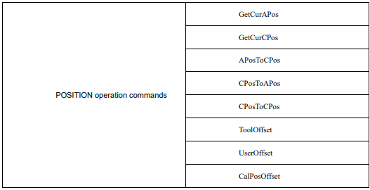
GetCurAPos
Get the position in the current joint coordinate system, and assign it to the Apos variables. The command parameters are described as below:
GetCurAPosP
P: Joint position
Data type: APOS
Meaning: The current position of the robot in the joint coordinate system.
For example:

GetCurCPos
Get the Cartesian space position in the current coordinate system (world coordinates or user coordinates), and assign it to the Cpos variables. The command parameters are described as below:
GetCurCPosP
P: Cartisian position
Data type: CPOS
Meaning: Cartesian position of the robot in the current coordinate system (World or User).
For example:

APosToCPos
This command is used for robot position point transformation. By utilizing the provided APos point, target CPos point, user coordinate system, and Tool parameters, it is possible to convert the APos point into the CPos point. The command parameters are described as below:
APosToCPosOP TP Tool Coord
OP: Original position (originalposition)
Data type: APOS
Meaning: The joint position before conversion.
TP: Target position (target position)
Data type: CPOS
Meaning: The target Cartesian space position.
Tool: Target Tool Parameters (target tool param)
Data type: TOOL
Meaning: The target tool parameters.
Coord: Target coordinates (target usercoord)
Data type: USERCOORD, EXTTCP, POSITIONER
Meaning: The reference coordinates
For example:

CPosToAPos
This command is used for robot position point transformation. By utilizing the provided CPos point, its associated user coordinate system, and tool parameters, it is possible to convert the CPos point into the APos point. The command parameters are described as below:
CPosToAPosOP Tool Coord TP
OP: Original position (originalposition)
Data type: CPOS
Meaning: The Cartesian space position before the conversion.
Tool: Original tool Parameters (originaltool param)
Data type: TOOL
Meaning: The tool parameters before the conversion.
Coord: Original coordinates (originalusercoord)
Data type: USERCOORD, EXTTCP, POSITIONER
Meaning: The parameter of the reference coordinate system before conversion.
TP: Target position (target position)
Data type: APOS
Meaning: The joint position after the conversion.
For example:

CPosToCPos
The command of robot position point conversion, through which CPos points can be converted to CPos points. Being given the CPos point, as well as the user coordinates and tool parameters of the target CPos point to be converted, the value of the target CPos point can then be derived. The command parameters are described as below:
CPosToCPosOP OTool OCoord TP TTool TCoord
OP: Original position (originalposition)
Data type: CPOS
Meaning: The Cartesian space position before the conversion.
Tool: Original tool Parameters (originaltool param)
Data type: TOOL
Meaning: The Tool parameters before the conversion.
OCoord: Original coordinates (originalusercoord)
Data type: USERCOORD, EXTTCP, POSITIONER
Meaning: The parameter of coordinate system before the conversion.
TP: Target position (target position)
Data type: CPOS
Meaning: The target Cartesian space position.
TTool: Target Tool Parameters (targettool param)
Data type: TOOL
Meaning: The parameter of target tool.
TCoord: Target coordinates (targetusercoord)
Data type: USERCOORD, EXTTCP, POSITIONER
Meaning: The parameter of target reference coordinate system.
For example:

ToolOffset
By using this command, a new tool coordinate system can be generated by rotating or offsetting the reference tool coordinate system. The robots TCP can then perform positional movements in the corrected coordinate system, without the need to reprogram points. This effectively improves on-site debugging efficiency and reduces the complexity of debugging. The command parameters are described as below:
ToolOffset F1 P F2
F1: Reference Tool Parameters (Tool1)
Data type: TOOL
Meaning: The parameters defining the original reference tool coordinate system.
P: Offset
Data type: DCPOS
Meaning: The offset of the new tool coordinate system relative to the original tool parameters.
F2: Target Tool Parameters (Tool2)
Data type: TOOL
Meaning: The new tool parameters that are obtained by offsetting based on the reference tool parameters.
For example:

UserOffset
By using this command, a new user coordinate system can be generated by rotating or offsetting the reference user coordinate system. The robots T CP can then perform positional movements in the corrected coordinate system, without the need to reprogram points. This effectively improves on-site debugging efficiency and reduces the complexity of debugging. The command parameters are described as below:
UserOffsetF1PF2
F1: User Coordinate System (Usercoord1)
Data type: USERCOORD
Meaning: The parameter of the user coordinate system before conversion.
P: Offset
Data type: DCPOS
Meaning: The offset of the new user coordinate system relative to the parameters of original user coordinate system.
F2: Target User Coordinate System Parameters (Usercoord2)
Data type: USERCOORD
Meaning: The parameter of new user coordinate system obtained upon the offset of the reference user coordinate system.
For example:

CalPosOffset
The Calculate Position Point Offset Result command. It calculates the position value after the original position has been offset relative to the coordinates or tool, based on the original position amount and the relative offset amount. The command parameters are described as below:
CalPosOffset OP RP T Tool Coord TP
OP: Original position (originalposition)
Data type: APOS/CPOS
Meaning: The start point of the offset motion.
RP: Relative offset (Rel position)
Data type: DCPOS
Meaning: The increment of the position to be moved relative to the original position.
T: Reference coordinates (RefSys)
Data type: enum (COORD/TOOL)
− COORD: The user coordinate system.
− TOOL: The tool coordinate system.
Meaning: The reference coordinate system, either Cartesian or tool.
Tool: Target Tool Parameters (target tool param)
Data type: TOOL
Meaning: Target Tool Parameters.
Coord: Target coordinates (target usercoord)
Data type: USERCOORD, EXTTCP, POSITIONER
Meaning: The reference coordinate system.
TP: Target position (target position)
Data type: CPOS
Meaning: The target Cartesian position.
For example:

3.7 Bit operation commands
The list of bit operation commands:
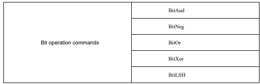

BitAnd
This command performs a bitwise AND operation on two operands and assigns the result to the first operand, achieving the bitwise AND operation. The command parameters are described as below:
BitAndI1 I2
I1: Operand 1 (data1)
Data type: INT
Meaning: Data to be manipulated,the result of the operation is also assigned to this operand.
I2: Operand 2 (data2)
Data type: INT
Meaning: Data to be compared.
For example:

BitNeg
This command performs a bitwise NOT operation on an operand and assigns the result to that operand, achieving the bitwise NOT operation. Additionally, the NOT operation only applies to the last 16 bits of the operand. The command parameters are described as below:
BitNegI1
I1: Operand (data)
Data type: INT
Meaning: Data to be manipulated, and the result of the operation is also assigned to this operand.
For example:

BitOr
This command performs a bitwise OR operation on two operands and assigns the result to the first operand, achieving the bitwise OR operation. The command parameters are described as below:
BitOrI1 I2
I1: Operand 1 (data1)
Data type: INT
Meaning: Data to be manipulated,the result of the operation is also assigned to this operand.
I2: Operand 2 (data2)
Data type: INT
Meaning: Data to be compared.
For example:

BitXOr
This command performs a bitwise XOR operation on two operands and assigns the result to the first operand, achieving the bitwise XOR operation. The command parameters are described as below:
BitXOrI1 I2
I1: Operand 1 (data1)
Data type: INT
Meaning: Data to be manipulated,the result of the operation is also assigned to this operand.
I2: Operand 2 (data2)
Data type: INT
Meaning: Data to be compared.
For example:

BitLSH
This command performs a bitwise left shift operation on two operands and assigns the result to the first operand, achieving the bitwise left shift operation. The command parameters are described as below:
BitLSHI1 I2
I1: Operand 1 (data1)
Data type: INT
Meaning: Data to be manipulated,the result of the operation is also assigned to this operand.
I2: Operand 2 (data2)
Data type: INT
Meaning: Data to be compared.
For example:

BitRSH
This command performs a bitwise right shift operation on two operands and assigns the result to the first operand, achieving the bitwise right shift operation. The command parameters are described as below:
BitRSHI1 I2
I1: Operand 1 (data1)
Data type: INT
Meaning: Data to be manipulated,the result of the operation is also assigned to this operand.
I2: Operand 2 (data2)
Data type: INT
Meaning: Data to be compared.
For example:

3.8 CLOCK commands
The list of CLOCK commands:
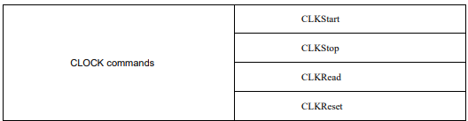
CLKStart
This command is used to start a specific clock. Once started, you can see that the state of the specified clock variable in the variable list is set to true. The command parameters are described as below:
CLKStartclk
clk: clock)
Data type: CLOCK
Meaning: The variable of the clock to be started.
For example:

CLKStop
Stop the specified clock (its state is false, but will not be reset). The command parameters are described as below:
CLKStopclk
clk: clock
Data type: CLOCK
Meaning: The variable of the clock to be stopped.
For example:

CLKRead
Read the value of the specified clock, by checking the value corresponding to the variable in the list of variables.
The command parameters are described as below:
CLKReadclk
clk: clock
Data type: CLOCK
Meaning: The variable of the clock to be read from.
For example:

CLKReset
This command is used to reset the state and value of a specific clock. The command parameters are described as below:
CLKResetclk
clk: clock
Data type: CLOCK
Meaning: The variable of the clock to be reset.
For example:

3.9 AREA commands
The list of AREA commands:
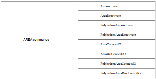
AreaActivate
Activate the standard AREA command to make the specified standard area be valid. The command parameters are described as below:
AreaActivateArea
Area: Standard AREA variable (Area)
Data type: AREA
Meaning: The variable of the standard AREA to be activated.
For example:

AreaDeactivate
This is the command for deactivating standard AREA commands to invalidate the specified standard area.
The command parameters are described as below:
AreaDeactivateArea
Area: Standard AREA variable (Area)
Data type: AREA
Meaning: The variable of the standard AREA to be deactivated.
For example:

PolyhedronAreaActivate
Activate the polyhedron AREA command to enable the specified polyhedron area. The command parameters are described as below:
PolyhedronAreaActivate Polyhedron
Polyhedron: Polyhedron AREA variable (Polyhedron)
Data type: POLYHEDRON
Meaning: The variable of polyhedron area to be activated.
For example:

PolyhedronAreaActivate
Activate the polyhedron AREA command to enable the specified polyhedron area. The command parameters are described as below:
PolyhedronAreaActivate Polyhedron
Polyhedron: Polyhedron AREA variable (Polyhedron)
Data type: POLYHEDRON
Meaning: The variable of polyhedron area to be activated.
For example:

PolyhedronAreaDeactivate
Deactivate the polyhedron AREA command to disable the specified polyhedron area. The command parameters are described as below:
PolyhedronAreaDeactivate Polyhedron
Polyhedron: Polyhedron AREA variable (Polyhedron)
Data type: POLYHEDRON
Meaning: The variable of polyhedron area to be deactivated.
For example:

AreaConnectIO
The command to bind an AREA IO, by which an input port can be bound to the selected area and specify a high and low active level for controlling the start and stop of the robot. The command parameters are described as below:
AreaConnectIOArea IoType IoPort IoPol
Area: Standard AREA variable (Area)
Data type: AREA
Meaning: The standard area variable to be bound.
IoType: IO type (IoType)
Data type: enum (DI/SIMDI)
Meaning: The type of IO port to be bound.
− DI: Actual DI.
− SIMDI: Virtual DI.
IoPort: IO port number (IoPort)
Data type: int
Meaning: The IO port number to be bound.
IoPol: IO polarity (IoPolarity)
Data type: enum (HIGH/LOW)
Meaning: The IO polarity to be bound.
− HIGH: Absolute transition.
− LOW: The type of default.
AreaDisConnectIO
The command to unbind the area IO, by which the binding to the selected area input port can be removed. The command parameters are described as below:
AreaDisConnectIO Area
Area: Standard AREA variable (Area)
Data type: AREA
Meaning: The standard area variable that needs to be unbound.
PolyhedronAreaConnectIO
The command to bind an area IO, by which an input port can be bound to the selected area and a high and low active level can be specified for controlling the start and stop of the robot. The command parameters are described as below:
PolyhedronAreaConnectIO Polyhedron IoType IoPort IoPol
Polyhedron: Polyhedron AREA variable (Polyhedron)
Data type: POLYHEDRON
Meaning: the polyhedron area variable to be bound.
IoType: IO type (IoType)
Data type: enum (DI/SIMDI)
Meaning: Type of IO port to be bound.
− DI: Actual DI.
− SIMDI: Virtual DI.
IoPort: IO port number (IoPort)
Data type: int
Meaning: The IO port number to be bound.
IoPol: IO polarity (IoPolarity)
Data type: enum (HIGH/LOW)
Meaning: The IO polarity to be bound.
− HIGH: Absolute transition.
− LOW: The type of default.
PolyhedronAreaDisConnectIO
Unbind area IO command, by which the binding to the selected area input port can be removed. The command parameters are described as below:
PolyhedronAreaDisConnectIO Polyhedron
Polyhedron: Polyhedron AREA variable (Polyhedron)
Data type: POLYHEDRON
Meaning: The polyhedron AREA variable to be unbound.
3.10 Visual commands
The list of visual commands:
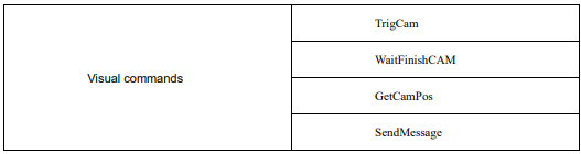
TrigCam
This is the command to trigger the camera shooting. The command parameters are described as below:
TrigCamtiid
ti: Camera trigger parameter (trigger info)
Data type: string
Meaning: The camera trigger parameter.
id: Camera index parameter (camera id)
Data type: int
Meaning: The camera index parameter.
For example:

WaitFinishCAM
This is the command for waiting for the camera to finish shooting. The command parameters are described as below:
WaitFinishCAMwtid
wt: wait time
Data type: int
Meaning: The waiting time for the camera to complete capturing an image, ranging from 0 to 20000 ms.
id: Camera index parameter (camera id)
Data type: int
Meaning: The camera index parameter.
For example:

GetCamPos
This command is used to obtain the position of the camera. The command parameters are described as below:
GetCamPosP tarID ret id
P: Target position (target position)
Data type: CPOS
Meaning: The camera has to get the target position.
tarID: Target position (targetID)
Data type: INT
Meaning: ID value of the target object.
ret: valid
Data type: INT
Meaning: Whether the retrieved position point is valid.
id: Camera index parameter (camera id)
Data type: int
Meaning: The camera index parameter.
For example:

SendMessage
Send a string message, which can be used for 3D visual commands. It sends the specified string to the camera, and enables the camera to shoot. The command parameters are described as below:
SendMessagemsg id
msg: message info
Data type: string
Meaning: The content of the message sent.
id: Camera index parameter (camera id)
Data type: int
Meaning: The camera index parameter.
For example:

3.11 Palletizing commands
The list of palletizing commands:
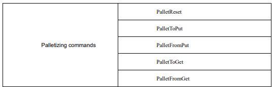
PalletReset
This is the command for palletizing reset. When a pallet is forced to stop before the palletizing is completed, call this command to restore it. The command parameters are described as below:
PalletResetPalletName actPart
PalletName: Palletizing name (Pallet Name)
Data type: PALLET variable
Meaning: The current pallet information variable
actPart: Number of workpieces in the pallet (ActPart)
Data type: int
Meaning: The current quantity of workpieces placed on the pallet. The range is set between 0 and the maximum capacity of the pallet.
For example1:

For example, Pallet0 with a maximum number of workpieces of 60 will halt when 8 workpieces have been placed. Call "PalletReset (Pallet0, 8);" to restart the palletizing of subsequent workpieces.
PalletToPut
This is the command for putting workpieces. The command parameters are described as below:
PalletToPutPalletName[V] [B] [C]
(Note: parameters indicated with [] are optional)
PalletName: Pallet Name
Data type: PALLET variable
Meaning: The current pallet information variable
[V]: Target speed (Velo)
Data type: SPEED variable
Meaning: To specify the speed at which the robot performs the PalletToPut operation, including the translational speed of the robots end effector, the rotational speed, and the movement speed of external axes.
Note: This parameter is optional and defaults to V4000.
[B]: Transition type (BlendType)
Data type: enum (FINE/RELATIVE/DEFAULT)
Meaning: The way of transition when the robot approaches the endpoint.
− FINE: No transition.
− RELATIVE: Relative transition.
− ABSOLUTE: Absolute transition.
− DEFAULT: The type of default.
Note: This parameter is optional and defaults to FINE.
[C]: Transition Value (BlendValue)
Data type: ZONE
Meaning: The transition value when the robot approaches the endpoint.
Note: This parameter is optional and defaults to C100.
For example1:

The palletizing position is calculated based on the first taught workpiece position as well as the configured palletizing distance. Add the set palletizing distance to the position of the previous workpiece, so as to get the position of the next workpiece, as shown in Figure 3-5.
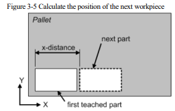
According to Figure 3-6, the defaulted palletizing sequence starts from X. Arrange all the parts in the x direction first, and then the next row. Arrange the workpiece in the x direction until the pre-determined number of workpieces in the x direction is reached.
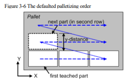
When starting placement for a new row, the position data of the workpiece in the new row will be produced by adding the offset in the y direction to the position of the workpiece in the first row.
The default palletizing sequence is x y z. First, put the workpiece in the x direction and then proceed to the second row. The placement of the first part of the new row starts at the position shown in the figure below.
They will be put on the next row if the current row is full. After all the rows in this layer are filled, the xy layer repeats translation in the z direction until it is fully palletized.
Figure 3-7 illustrates the recommended path for placement.
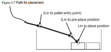
Following motion commands are executed when PalletToPut command is called:
The robot moves to the entry position of the pallet in a linear motion (optional)
The robot moves to the front position of the palletizing point in a linear motion (optional)
The robot moves to the arranged position of the workpiece in a linear motion (required)
PalletFromPut
This is the command used when the robot moves away from the putting position after the workpieces are placed. The command parameters are described as below:
PalletFromPutPalletName [V] [B] [C]
(Note: parameters indicated with [] are optional)
PalletName: Palletizing name (Pallet Name)
Data type: PALLET variable
Meaning: The current pallet information variable
[V]: Target speed (Velo)
Data type: SPEED variable
Meaning: To specify the speed at which the robot performs the PalletFromPut operation, including the translational speed of the robots end effector, the rotational speed, and the movement speed of external axes.
Note: This parameter is optional and defaults to V4000.
[B]: Transition type (BlendType)
Data type: enum (FINE/RELATIVE/DEFAULT)
Meaning: The way of transition when the robot approaches the endpoint.
− FINE: No transition.
− RELATIVE: Relative transition.
− ABSOLUTE: Absolute transition.
− DEFAULT: The type of default.
Note: This parameter is optional and defaults to FINE.
[C]: Transition Value (BlendValue)
Data type: ZONE
Meaning: The transition value when the robot approaches the endpoint.
Note: This parameter is optional and defaults to C100.
For example1:

This is the command for the opposite action of workpiece placement, making the robot leaves from the position of the workpiece that has been placed.
The recommended path when leaving is shown in Figure 3-8.
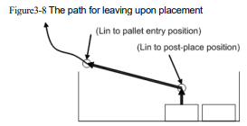
Following motion commands are executed when calling the PalletFromPut command:
The robot moves to the rear of palletizing point in a linear motion (optional)
The robot moves to the entry position of the pallet in a linear motion (optional)
If neither the post-pallet point nor the entry position has been set, the robot will maintain its current posture when the PalletFromPut command is executed.
PalletToGet
This is the command for picking the workpiece. When executing this command, the robot will move from the current point to the palletizing point of the target workpiece to Pick such workpiece. The command parameters are described as below:
PalletToGetPalletName[V] [B] [C]
(Note: parameters indicated with [] are optional)
PalletName: Palletizing name (Pallet Name)
Data type: PALLET variable
Meaning: The current pallet information variable
[V]: Target speed (Velo)
Data type: SPEED variable
Meaning: To specify the speed at which the robot performs the PalletToGet operation, including the translational speed of the robots end effector, the rotational speed, and the movement speed of external axes.
Note: This parameter is optional and defaults to V4000.
[B]: Transition type (BlendType)
Data type: enum (FINE/RELATIVE/DEFAULT)
Meaning: The way of transition when the robot approaches the endpoint.
− FINE: No transition.
− RELATIVE: Relative transition.
− ABSOLUTE: Absolute transition.
− DEFAULT: The type of default.
Note: This parameter is optional and defaults to FINE.
[C]: Transition Value (BlendValue)
Data type: ZONE
Meaning: The transition value when the robot approaches the endpoint.
Note: This parameter is optional and defaults to C100.
For example1:

The recommended path for picking is shown in Figure3-9.
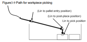
Following motion commands are executed when calling the PalletToGet command:
The robot moves to the entry position of palletizing point in a linear motion (optional)
The robot moves to the post position of the pallet in a linear motion (optional)
The robot moves to the picking position in a linear motion (required)
After making these motion sequences, the robot reaches the position where the workpiece is placed, then closes the fixture for picking workpieces.
PalletFromGet
This is the command indicating the process of leaving after workpiece pick. When executing this instruction, the robot will leave from the palletizing point where the workpiece is picked. The command parameters are described as below:
PalletFromGetPalletName [V] [B] [C]
(Note: parameters indicated with [] are optional)
PalletName: Palletizing name (Pallet Name)
Data type: PALLET variable
Meaning: The current pallet information variable
[V]: Target speed (Velo)
Data type: SPEED variable
Meaning: To specify the speed at which the robot performs the PalletFromGet operation, including the translational speed of the robots end effector, the rotational speed, and the movement speed of external axes.
Note: This parameter is optional and defaults to V4000.
[B]: Transition type (BlendType)
Data type: enum (FINE/RELATIVE/DEFAULT)
Meaning: The way of transition when the robot approaches the endpoint.
− FINE: No transition.
− RELATIVE: Relative transition.
− ABSOLUTE: Absolute transition.
− DEFAULT: The type of default.
Note: This parameter is optional and defaults to FINE.
[C]: Transition Value (BlendValue)
Data type: ZONE
Meaning: The transition value when the robot approaches the endpoint.
Note: This parameter is optional and defaults to C100.
For example1:

The recommended path for picking is shown in Figure3-10.
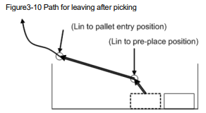
Following motion commands are executed when calling the PalletFromGet command:
The robot moves to the palletizing point in a linear motion (optional)
The robot moves to the entry position of the pallet in a linear motion (optional)
If neither the post-point nor the entry position of the pallet point has been set, the robot will maintain its current posture when executing the PalletFromGet command.
3.12 Socket commands
The list of Socket commands:
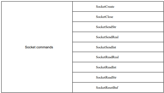
SocketCreate
Create a socket client for purpose of data exchange with the server. Create a client locally and connect it with the server-side according to the server-side parameters transmitted.
SocketCreateSN IP P RV
SN: Socket name
Parameter type: Socket variable
IP: IP address
Parameter type:string
Meaning: The IP address of the server to be connected to.
P: Port number
Parameter type:int
Meaning: The port number of the server to be connected.
RV: Operation returned value
Parameter type: INT variable
Meaning: To create the operation returned value variable, a returned value of 0 indicates success, while a returned value of 1 indicates failure.
For example:

SocketClose
Close the socket client that has been created before.
SocketClose SN RV
SN: Socket name
Parameter type:Socket variable
Meaning: The socket created by the SocketCreate
RV: Operation returned value
Parameter type: INT variable
Meaning: The returned value variable of operation, for which a returned value of 0 indicates success, while a returned value of 1 indicates failure.
For example:

SocketSendStr
Send a string to the server that has established a connection.
SocketSendStr SN SD RV
SN: Socket name
Parameter type: Socket variable
Meaning: The socket created by the SocketCreate
SD: Send data
Parameter type: STRING constant or STRING variable
RV: Operation returned value
Parameter type: INT variable
Meaning: The returned value variable of operation, for which a returned value of 0 indicates success, while a returned value of 1 indicates failure.
For example:

SocketSendReal
Send a real array to the connected server.
SocketSendReal SN RA RV
SN: Socket name
Parameter type: Socket variable
Meaning: The socket created by the SocketCreate
RA: Real array data sent (Real array)
Parameter type: Real array
RV: Operation returned value
Parameter type: INT variable
Meaning: The returned value variable of operation, for which a returned value of 0 indicates success, while a returned value of 1 indicates failure.
For example:

SocketSendInt
Send an int array to the connected server.
SocketSendIntSN IA RV
SN: Socket name
Parameter type: Socket variable
Meaning: The socket created by the SocketCreate
IA: Int array data sent (Int array)
Parameter type: int array
RV: Operation returned value
Parameter type: INT variable
Meaning: The returned value variable of operation, for which a returned value of 0 indicates success, while a returned value of 1 indicates failure.
For example:

SocketReadReal
Read the string sent from the server-side, and store it in the form of a real array.
Wait for and receive the string sent by the server. Its format is [1.1,2.2,3.3,4.4] (that is, the beginning and the end of the data are[], and the figures are separa ted by,). The robot system will split and parse the received string, and store it in the array in sequence.
SocketReadReal SN DN RD DT RV
SN: Socket name
Parameter type: Socket variable
Meaning: The socket created by the SocketCreate
DN: Count of data (Data num)
Parameter type:int
RD: The data actually read (Real data)
Parameter type: RealOneArray variable
DT: Detection time (Detection time)
Parameter type:int
Meaning: The waiting time (ms) for data to be sent from the server, with an alarm triggered if a timeout occurs
RV: Operation returned value
Parameter type:INT variable
Meaning: The returned value variable of operation, for which a returned value of 0 indicates success, while a returned value of 1 indicates failure.
For example:

SocketReadInt
Read the string sent from the server and store it in the form of an int array.
Wait for and receive the string sent by the server-side. Its format is [1,2,3,4] (the beginning and the end of the data are[], and the figures are separated by,). The robot system will split and parse the received string, and store it in the array in sequence.
SocketReadInt SN DN ID DT RV
SN: Socket name
Parameter type:Socket variable
Meaning: The socket created by the SocketCreate
DN: Count of data (Data num)
Parameter type:int
ID: The data actually read (Int data)
Parameter type: IntOneArray variable
DT: Detection time (Detection time)
Parameter type: int
Meaning: The waiting time (ms) for data to be sent from the server, with an alarm triggered if a timeout occurs
RV: Operation returned value
Parameter type:INT variable
Meaning: The returned value variable of operation, for which a returned value of 0 indicates success, while a returned value of 1 indicates failure.
For example:

SocketReadStr
Read the string sent from the server-side, and store it in the form of a string variable.
Wait and receive the string sent by the server. Its format is [Hello world!] (The beginning and the end of the data are[]). The robot system will store the received string in the string variable.
SocketReadStr SN SD DT RV
SN: Socket name
Parameter type:Socket variable
Meaning: The socket created by the SocketCreate
SD: The data actually read (String data)
Parameter type:STRING variable
DT: Detection time (Detection time)
Parameter type:int
Meaning: The waiting time (ms) for data to be sent from the server, with an alarm triggered if a timeout occurs
RV: Operation returned value
Parameter type:INT variable
Meaning: The returned value variable of operation, for which a returned value of 0 indicates success, while a returned value of 1 indicates failure.
For example:

SocketResetBuf
This command is used to reset local cache strings. It is intended to reset the data already received in the cache before the SocketRead read command is executed, to avoid the problem of misplaced data reading.
SocketReadStr SN
SN: Socket name
Parameter type:Socket variable
Meaning: The socket created by the SocketCreate
For example:

3.13 SoftFloat commands
The list of SoftFloat commands:

SoftFloatStart
This command allows the robot to transition from a rigid state to a compliant state without using external sensors or modifying the mechanical structure. Once the command is activated, the robots end effector can move linearly along the specified direction in response to external forces. The command parameters are described as below:
SoftFloatStartType Coordinate[Tool ] [User]DirectionSensitivity
(Note: parameters indicated with [] are optional)
Type: Type of SoftFloat (SoftType)
Data type: enum ("CART")
Meaning: Type of SoftFloat. Only the linear SoftFloat is supported currently.
---"CART": The linear type.
Coordinate: Reference coordinate system (Coordinate)
Data type: enum ("WORLD","TOOL","USER")
Meaning: SoftFloat reference coordinate system
---"WORLD": World Coordinates
---"TOOL": Tool Coordinates
---"USER": User Coordinates
Tool: Coordinate system number (SoftTool)
Data type: TOOL variable
Meaning: Tool Parameters variable. This parameter is only valid when the reference coordinate system is set to "TOOL".
Note: This parameter is invalid when the reference coordinate system is set to “WORLD” or “USER”.
User: Coordinate system number (SoftUser)
Data type: USERCOOR variable
Meaning: The variable of user coordinate system. This parameter is only valid when the reference coordinate system is set to "USER".
Note: This parameter is invalid when the reference coordinate system is set to “WORLD” or “TOOL”.
Direction: SoftFloat direction (SoftDirection)
Data type: enum ("X","Y","Z")
Meaning: SoftFloat direction
---"X": The X direction of the selected reference coordinate system or its number
---"Y": The Y direction of the selected reference coordinate system or its number
---"Z": The Z direction of the selected reference coordinate system or its number
Sensitivity: SoftFloat sensitivity (SoftSensitivity)
Data type: enum ("HIGH","MidHigh","MID","MidLow","LOW")
Meaning: The SoftFloat compliance parameter
---"HIGH": The highest level of compliance
---"MidHigh": The second highest level of compliance
---"MID": The medium compliance
---"MidLow": The second lowest level of compliance
---"LOW": The lowest level of compliance
For example1:

SoftFloatStop
Use this command to turn off the SoftFloat function.
For example1:

3.14 Conveyor tracking commands
The list of conveyor tracking commands:
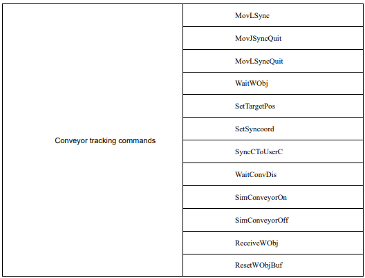
MovLSync
The MovLSync command is a conveyor synchronous motion command. It allows the robots TCP to move linearly at the set speed to the target position while maintaining synchronization with the conveyors motion. Similar to MovJ, additional IO operations can be performed after executing this command. The command parameters are described as below:
MovLSyncP [V][Tool ] Coord [PayLoad][SyncGoto]HeightConvyGoto[DO]
(Note: parameters indicated with [] are optional)
P: Target position (Target Pos)
Data type: CPOS variable
Meaning: The target point to be followed is specified as an offset relative to the recognized point of the target object, rather than being obtained through teaching.
[V]: Target speed (Velo)
Data type: SPEED variable
Meaning: To specify the speed at which the robot executes MovLSync. It includes the translational speed of the robots end effector, rotational speed, and speed of external axes, among others. In this case, the tcp and ori components in the SPEED variable are valid. If there are external axes present, the exj_l and exj_r components in the SPEED variable are valid as well.
Note: This parameter is optional and defaults to V4000.
[Tool]: Tool Parameters (Tool)
Data type: TOOL variable
Meaning: The tool parameters used when the robot executes the path.
Note: This parameter is optional and defaults to the Tool Parameters set in the current system.
Coord: Coordinate System Parameters (Coord)
Data type: SYNCOORD variable
Meaning: The moving coordinate system used by the robot when executing this path should be consistent with the moving coordinate system enabled in the conveyor configuration interface.
[PayLoad]: Workpiece load (PayLoad)
Data type: PAYLOAD variable
Meaning: The workpiece load parameter used by the robot when executing the path.
Note: This parameter is optional and defaults to the payload parameters set in the current system.
[SyncGoto]: Jump labels on abort during sync (SyncGoto)
Data type: label
Meaning: Used for the abort function during synchronization. When the robot fails to achieve synchronization with the target object during the MovLSync command, the program pointer will jump to the line where the specified label is located to execute the abort operation. Users can add corresponding commands under this label based on the on-site conditions.
Note: This parameter is optional. When set to default, it will jump to the Label used for "Jump label when aborted after synchronization".
Height: Lift height when aborting after sync (Height)
Data type: real
Meaning: The distance to lift when aborting after synchronization, relative to the positive direction of the dynamic coordinate systems Z -axis.
ConvyGoto: Jump labels on abort after sync (ConvyGoto)
Data type: label
Meaning: Used for aborting during the tracking process. When the robot is unable to continue tracking during the tracking motion, specifically when the subsequent commands after the MovLSync fail to execute, the program pointer will jump to the line where the specified label is located to perform the aborting operation.
Under this label, users can include corresponding commands based on the on-site conditions.
[DO]: IO operations to be executed after motion done (Add Do)
Data type: string
Meaning: The IO operations that can be triggered after the robot completes the command:
− NULL: No operation.
− IO COMMANDS: EXECUTING IO OPERATION. THE IO COMMANDS CURRENTLY AVAILABLE ARESetDo, SetAo, SetSimDo, SetSimAo, PulseOut, PulseSimOut, SetDO8421, SetDIEdge, SetSimDIEdge.
MovJSyncQuit
The MovJSyncQuit command is used to exit the conveyor synchronized joint motion. This command allows the robot to move at the set speed to exit the synchronized motion with the conveyor. The robot will move to the target position using joint motion. If the starting and ending postures of the motion are different, the robots posture will rotate synchronously with the position during the motion to reach the final posture. Similar to MovJ, additional IO operations can be performed after executing this command. The command parameters are described as below:
MovJSyncQuitP [V] [B] [C][Tool] Coord [PayLoad][DO]
(Note: parameters indicated with [] are optional)
P: Target position (Target Pos)
Data type: APOS or CPOS variable
Meaning: The target point position in the coordinate system.
[V]: Target speed (Velo)
Data type: SPEED variable
Meaning: To specify the speed at which the robot executes MovJSyncQuit. It includes the translational speed of the robots end effector, rotational speed, and speed of external axes, among others. In this case, the tcp and ori components in the SPEED variable are valid. If there are external axes present, the exj_l and exj_r components in the SPEED variable are valid as well.
Note: This parameter is optional and defaults to V4000.
[B]: Transition type (BlendType)
Data type: enum (FINE/RELATIVE/DEFAULT)
Meaning: The way of transition when the robot approaches the endpoint.
− FINE: No transition.
− RELATIVE: Relative transition.
− ABSOLUTE: Absolute transition.
− DEFAULT: The type of default.
Note: This parameter is optional and defaults to FINE.
[C]: Transition Value (BlendValue)
Data type: ZONE variable
Meaning: The transition value when the robot approaches the endpoint.
Note: This parameter is optional and defaults to C100.
[Tool]: Tool Parameters (Tool)
Data type: TOOL variable
Meaning: The tool parameters used when the robot executes the path.
Note: This parameter is optional and defaults to the Tool Parameters set in the current system.
Coord: Coordinate System Parameters (Coord)
Data type: USERCOOR variable
Meaning: The user coordinate system used by the robot when executing the path.
[PayLoad]: Workpiece load (PayLoad)
Data type: PAYLOAD variable
Meaning: The workpiece load parameter used by the robot when executing the path.
Note: This parameter is optional and defaults to the payload parameters set in the current system.
[DO]: IO operations to be executed after motion done (Add Do)
Data type: string
Meaning: The IO operations that can be triggered after the robot completes the command:
− NULL: No operation.
− IO COMMANDS: EXECUTING IO OPERATION. THE IO COMMANDS CURRENTLY AVAILABLE ARESetDo, SetAo, SetSimDo, SetSimAo, PulseOut, PulseSimOut, SetDO8421, SetDIEdge, SetSimDIEdge.
MovLSyncQuit
The MovLSyncQuit command is used to exit the conveyor synchronized linear motion. This command allows the robots TCP point to move at the set speed to exit the synchronized motion with the conveyo r. The robot will move to the target position using linear motion. If the starting and ending postures of the motion are different, the robots posture will rotate synchronously with the position during the motion to reach the final posture. Similar to MovJ, additional IO operations can be performed after executing this command. The command parameters are described as below:
MovLSyncQuit P [V] [B] [C][Tool] Coord [PayLoad][DO]
(Note: parameters indicated with [] are optional)
P: Target position (Target Pos)
Data type: APOS or CPOS variable
Meaning: The target point position in the coordinate system.
[V]: Target speed (Velo)
Data type: SPEED variable
Meaning: To specify the speed at which the robot executes MovLSyncQuit. It includes the translational speed of the robots end effector, rotational speed, and speed of external axes, among others. In this case, the tcp and ori components in the SPEED variable are valid. If there are external axes present, the exj_l and exj_r components in the SPEED variable are valid as well.
Note: This parameter is optional and defaults to V4000.
[B]: Transition type (BlendType)
Data type: enum (FINE/RELATIVE/DEFAULT)
Meaning: The way of transition when the robot approaches the endpoint.
− FINE: No transition.
− RELATIVE: Relative transition.
− ABSOLUTE: Absolute transition.
− DEFAULT: The type of default.
Note: This parameter is optional and defaults to FINE.
[C]: Transition Value (BlendValue)
Data type: ZONE variable
Meaning: The transition value when the robot approaches the endpoint.
Note: This parameter is optional and defaults to C100.
[Tool]: Tool Parameters (Tool)
Data type: TOOL variable
Meaning: The tool parameters used when the robot executes the path.
Note: This parameter is optional and defaults to the Tool Parameters set in the current system.
Coord: Coordinate System Parameters (Coord)
Data type: USERCOOR variable
Meaning: The user coordinate system used by the robot when executing the path.
[PayLoad]: Workpiece load (PayLoad)
Data type: PAYLOAD variable
Meaning: The workpiece load parameter used by the robot when executing the path.
Note: This parameter is optional and defaults to the payload parameters set in the current system.
[DO]: IO operations to be executed after motion done (Add Do)
Data type: string
Meaning: The IO operations that can be triggered after the robot completes the command:
− NULL: No operation.
IO COMMANDS: EXECUTING IO OPERATION. THE IO COMMANDS CURRENTLY AVAILABLE ARESetDo, SetAo, SetSimDo, SetSimAo, PulseOut, PulseSimOut, SetDO8421, SetDIEdge, SetSimDIEdge.
WaitWObj
The command is used to wait for the position information of a workpiece on a specified conveyor belt from an external device within a specified duration. If the waiting condition is met within the set duration, the program will continue executing; if the condition is not met within the set duration, the timeout judgment value will be set to 1, and the program will continue executing.
The command parameters are described as below:
WaitWObj Coord T Ret [Goto]
Coord: Coordinate System Parameters (Coord)
Data type: SYNCOORD variable
Meaning: The moving coordinate system referenced for the position information of the workpiece that the robot is currently waiting for should be consistent with the moving coordinate system enabled in the conveyor configuration interface.
T: Duration (Time)
Data type: int
Meaning: The duration, in milliseconds, for waiting for the position information of the workpiece from the external device. When the value is 0, it will force a wait until the DI signal is satisfied, and then consider it as a successful execution.
Ret: Timeout judgment value (Timeout Flag)
Data type: INT
Meaning: To return the status after the command execution is done.
− 0: Signal is detected successfully
− 1: No signal is detected, and the command times out and returns.
[Goto]: Tag name for timeout jump (Value)
Data type: label
Meaning: The label name to jump to after a timeout occurs. This label should correspond to a LABEL command that has been taught in the currently loaded program, such as "Start". When a timeout occurs, the program pointer will jump to the command line associated with the specified label name.
Note: This parameter is optional and defaults to “No Jump”.
For example1:

SetTargetPos
This command is used to send the position information of the workpiece to the specified conveyor, enabling the robot to perform conveyor tracking. This command can only be executed when the trigger type selected in the conveyor interface is non-vision trigger type.
The command parameters are described as below:
SetTarget Coord P
Coord: Coordinate System Parameters (Coord)
Data type: SYNCOORD variable
Meaning: The moving coordinate system to which the current workpiece position information refers should be consistent with the moving coordinate system enabled in the conveyor configuration interface.
P: Target position (Target Pos)
Data type: CPOS variable
Meaning: The offset of the workpiece relative to the origin of the SYNCOORD coordinate system. Only the values for X, Y, and A are valid in this parameter.
SetSyncoord
The moving coordinate system set commands. It is used to set the current robot reference coordinates to moving coordinates. This command enables the current robot reference coordinates to be switched to a moving coordinate system, which can quickly teach the posture of the point position during the following process.
The command parameters are described as below:
SetSyncoord Coord
Coord: Coordinate System Parameters (Coord)
Data type: SYNCOORD variable
Meaning: The parameter of the coordinate system to which the robot is currently referenced, which
can only be set to variables of SYNCOORD.
SynCToUserC
The teaching reference coordinate system transformation command. It is used to calculate the coordinate system referenced during the path point teaching tracking synchronization.
The command parameters are described as below:
SynCToUserC Sync P Coord
Sync: Movable Coordinate System Parameters (SynCoord)
Data type: SYNCOORD variable
Meaning: The current moving coordinate system that the workpiece position information is referenced to should be consistent with the moving coordinate system enabled in the conveyor configuration interface.
P: Target position (Target Pos)
Data type: DCPOS variable
Meaning: Indicating the offset of the position of the workpiece entering the conveyor relative to the origin of the moving coordinate system.
Coord: Coordinate System Parameters (Coord)
Data type: USERCOORD variable
Meaning: The user coordinate system that is used as a reference when teaching the path waypoints after tracking sync.
WaitConvDis
It is used to enable the robot to move in the positive direction of the conveyor in synchronization with the conveyor up to a certain increment before executing subsequent commands, thus allowing the robot to delay the movement for a specified increment. Unlike the Wait commands, this command requires a fixed increment while the Wait command requires a fixed time.
The command parameters are described as below:
WaitConvDis Coord Dis
Coord: Coordinate System Parameters (Coord)
Data type: SYNCOORD variable
Meaning: The moving coordinate system that is used as a reference for the current position information of the workpiece. It should be consistent with the moving coordinate system enabled in the conveyor configuration interface.
Dis: Awaiting increment (Increment)
Data type: real
Meaning: The value of the increment in which the robot is to be synchronized. In mm for straight conveyors and in deg for disc conveyors.
SimConveyorOn
The Virtual Conveyor ON command. It is used to enable the virtual conveyor and specify its running speed.
The command parameters are described as below:
SimConveyorOnCoord Speed
Coord: Coordinate System Parameters (Coord)
Data type: SYNCOORD variable
Meaning: The moving coordinate system that is used as a reference for the current position information of the workpiece. It should be consistent with the moving coordinate system enabled in the conveyor configuration interface.
Speed: Conveyor speed (ConveyorSpeed)
Data type: real
Meaning: The speed at which the virtual conveyor runs.
SimConveyorOff
The Virtual Conveyor OFF command. It is used to disable the virtual conveyor.
The command parameters are described as below:
SimConveyorOffCoord
Coord: Coordinate System Parameters (Coord)
Data type: SYNCOORD variable
Meaning: The moving coordinate system that is used as a reference for the current position information of the workpiece. It should be consistent with the moving coordinate system enabled in the conveyor configuration interface.
ReceiveWObj
A command to set the receive status of workpiece data. This command can be used in combination to allow the robot system to not receive workpiece position information from vision or run programs within a certain segment of the path, to prevent instances of incorrect tracking and cater to various on-site processes
The command parameters are described as below:
ReceiveWObjCoordenableSts
Coord: Coordinate System Parameters (Coord)
Data type: SYNCOORD variable
Meaning: The moving coordinate system that is used as a reference for the current position information of the workpiece. It should be consistent with the moving coordinate system enabled in the conveyor configuration interface.
enableSts: Enable receive status (EnableSts)
Data type: enum (OFF/ON)
Meaning: Enables the robot system to receive information on the position of the workpiece.
ResetWObjBuf
A command to reset the queue of received workpiece data. It empties the queue of received and unexecuted workpiece information.
The command parameters are described as below:
ReceiveWObjCoord
Coord: Coordinate System Parameters (Coord)
Data type: SYNCOORD variable
Meaning: The moving coordinate system that is used as a reference for the current position information of the workpiece. It should be consistent with the moving coordinate system enabled in the conveyor configuration interface.
3.15 INTERRUPT commands
The list of INTERRUPT commands:
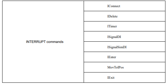

IConnect
The interrupt connection command. It binds the INTERRUPT identifier to the interrupt handler for operation, so that the system can execute the INTERRUPT program bound to the interrupt index when the trigger condition corresponding to the INTERRUPT identifier is met. The command parameters are described as below:
IConnect Interrupt TrigProg
Interrupt: INTERRUPT ID (Interrupt)
Data type: INTERRUPT variable
Meaning: The unique Interrupt index number.
TrigProg: Interrupt handler (TrigProgram)
Data type: program
Meaning: The handler to be called when the signal corresponding to this INTERRUPT index is satisfied.
Note: This parameter only allows for the selection of local programs and does not support global programs.
IDelete
The INTERRUPT release command. It removes any data associated with the INTERRUPT identifier in the system, effectively removing the detection of the INTERRUPT identifier and any corresponding execution data. The command parameters are described as below:
IDeleteInterrupt
Interrupt: INTERRUPT ID (Interrupt)
Data type: INTERRUPT variable
Meaning: The unique INTERRUPT index number.
ITimer
The timer INTERRUPT command is used to set the INTERRUPT detection mode as timer-based detection. This means that the system will periodically execute the INTERRUPT program based on the configured trigger time. The command parameters are described as below:
ITimerInterrupt timeMs
Interrupt: INTERRUPT ID (Interrupt)
Data type: INTERRUPT variable
Meaning: The unique INTERRUPT index number.
timeMs: Trigger time (TrigProgram)
Data type: int
Meaning: The timing detection time, range: 100~3000000ms.
ISignalDI
The input INTERRUPT command. It is used to set the INTERRUPT detection mode as DI edge signal detection. It monitors the rising/falling edge signal of DI in real time to process the corresponding INTERRUPT program of the robot. The command parameters are described as below:
ISignalDIInterrupt IO EdgeType
Interrupt: INTERRUPT ID (Interrupt)
Data type: INTERRUPT variable
Meaning: The unique INTERRUPT index number.
IO: Port variable (IO)
Data type: DI
Meaning: The DI port number to be monitored.
EdgeType: Trigger Edge type (EdgeType)
Data type: enum(RiseEdge/DownEdge)
Meaning: The type of DI edge signal to be monitored.
− RiseEdge: The rising edge signal.
− DownEdge: The falling edge signal.
ISignalSimDI
The virtual input port INTERRUPT command. It sets the detection of the INTERRUPT index to SimDI edge triggering, i.e. the rising/falling edge signals of SimDI are monitored in real time to process the corresponding INTERRUPT program of the robot. The command parameters are described as below:
ISignalSimDI Interrupt IO EdgeType
Interrupt: INTERRUPT ID (Interrupt)
Data type: INTERRUPT variable
Meaning: The unique INTERRUPT index number.
IO: Port variable (IO)
Data type: SimDI
Meaning: The virtual SimDI port number (SimDI type) to be monitored.
EdgeType: Trigger Edge type (EdgeType)
Data type: enum(RiseEdge/DownEdge)
Meaning: The type of SimDI edge signal to be monitored
− RiseEdge: The rising edge signal
− DownEdge: The falling edge signal
IEnter
The command that interrupts the current parsing and motion, stops the parsing and motion of the main program and switches to the INTERRUPT program.
Note: This command can only be executed in the INTERRUPT program.
IExit
The command to resume parsing and motion, which cuts the INTERRUPT program to background for execution and resumes parsing and motion of the main program.
Note: 1. This command can only be executed in the INTERRUPT program.
2. This command must be used in conjunction with the IEnter and MovToIPos commands.
MovToIPos
The Return Interrupt Point command. It is used to automatically move the robot back to the interrupted position in the main program using the specified motion. When an interrupt occurs, the system automatically stores the interrupted position in memory. When this command is executed, the interrupted position is retrieved from memory and the robot moves to that position. The command parameters are described as below:
MovToIPosModeV
Mode: Motion mode (Mode)
Data type: enum(MOVJ/MOVL)
Meaning: The mode of motion to the interrupt point
− MOVJ: Return to the target point as a joint motion
− MOVL: Return to the target point as a linear motion
V: Target speed (Velo)
Data type: SPEED
Meaning: The speed of motion to the interrupt point
Note: 1. This command can only be executed in the INTERRUPT program.
2. This command must be used in conjunction with the IEnter and IExit commands.
ExitCycle
The exit cycle command. When this command is executed, the system will immediately end the current INTERRUPT program, return the PC pointer to the start of the main program, and bring the system to a halt.
Note: 1. This command can only be executed in the INTERRUPT program.
2. This command must be used in conjunction with the IEnter command
3. When this command is executed, the system will jump to the "CycleLable" label command if it is taught by the main program, or to the first line of the program being loaded if it is not taught.
3.16 ARRAY commands
The list of ARRAY commands:

SetMatrix
Form a parallelogram in space with the specified three points and divide this parallelogram equally according to the set number of rows and columns to obtain a matrix point set.
The command parameters are described as below:
SetMatrixP1 P2 P3 Row Column
P1: Origin (HomePos)
Data type: CPOS variable
Meaning: Specifies the first point of the parallelogram,也称为原点.
P2: Last point in row direction (RowPos)
Data type: CPOS variable
Meaning: Specifies the last point in the row direction of the parallelogram.
P3: Last point in column direction (ColumnPos)
Data type: CPOS variable
Meaning: Specifies the last point in the column direction of the parallelogram.
Row: Number of rows (Row)
Data type: constant
Meaning: The number of rows of the generated matrix.
Column: Number of columns (Column)
Data type: constant
Meaning: The number of columns of the generated matrix.
For example:
Divide the quadrilateral formed by P1, P2 and P3 equally in 4 rows and 5 columns:
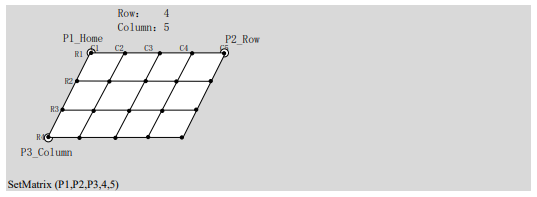
GetMatrix
The value of this point in the corresponding row after executing the SetMatrix command and assigned to the target point. The posture and additional axis angle values of the point as described in SetMatrix remain the same as the origin.
The command parameters are described as below:
GetMatrixRow Column TarPos
Row: Number of rows (Row)
Data type: INTtype variable
Meaning: The row number of the matrix from which the point is to be taken
Column: Number of columns (Column)
Data type: INTtype variable
Meaning: The column number of the matrix from which the point is to be taken
TarPos: Target point (TarPos)
Data type: CPOS variable
Meaning: Used to store the value of the picked point.
3.17 Mathematical Functions
This section provides an explanation of the “Mathematical Functions” that can be used.
sin
The sine trigonometric function
Parameter 1: A variable or constant of type int or REAL.
Function return value: A constant of type REAL.
cos
The cosine trigonometric function.
Parameter 1: A variable or constant of type int or REAL.
Function return value: A constant of type REAL.
tan
The tangent trigonometric function.
Parameter 1: A variable or constant of type int or REAL.
Function return value: A constant of type REAL.
asin
The inverse sine trigonometric function.
Parameter 1: A variable or constant of type int or REAL.
Function return value: A constant of type REAL.
acos
The inverse cosine trigonometric function.
Parameter 1: A variable or constant of type int or REAL.
Function return value: A constant of type REAL.
atan
The inverse tangent trigonometric function.
Parameter 1: A variable or constant of type int or REAL.
Function return value: A constant of type REAL.
atan2
X/Y inverse tangent value function, returning the value in radian from the X axis to the point (x, y).
Parameter 1: A variable or constant of type int or REAL.
Parameter 2: A variable or constant of type int or REAL.
Function return value: A constant of type REAL.
sinh
The hyperbolic sine function.
Parameter 1: A variable or constant of type int or REAL.
Function return value: A constant of type REAL.
cosh
The hyperbolic cosine function.
Parameter 1: A variable or constant of type int or REAL.
Function return value: A constant of type REAL.
tanh
The hyperbolic tangent function.
Parameter 1: A variable or constant of type int or REAL.
Function return value: A constant of type REAL.
log
The natural logarithmic function.
Parameter 1: A variable or constant of type int or REAL.
Function return value: A constant of type REAL.
log10
The logarithmic function of base 10.
Parameter 1: A variable or constant of type int or REAL.
Function return value: A constant of type REAL.
sqrt
The square root function.
Parameter 1: A variable or constant of type int or REAL.
Function return value: A constant of type REAL.
exp
The exponential function of base e.
Parameter 1: A variable or constant of type int or REAL.
Function return value: A constant of type REAL.
pow
The exponential function.
Parameter 1: int or real type variables or constants, base.
Parameter 2: int or real type variables or constants, exponent.
Function return value: The real constants.
deg
The radian to degree function.
Parameter 1: A variable or constant of type int or REAL.
Function return value: A constant of type REAL.
rad
The degree to radian function.
Parameter 1: A variable or constant of type int or REAL.
Function return value: A constant of type REAL.
fmod
The remainder function.
Parameter 1: int or real type variables or constants, dividend.
Parameter 2: int or real type variables or constants, divisor.
Function return value: The real constants.
floor
The floor function.
Parameter 1: A variable or constant of type int or REAL.
Function return value: A constant of type REAL.
random
Random integers selected from one of the 2 parameters.
Parameter 1: A variable or constant of type int or REAL.
Parameter 2: A variable or constant of type int or REAL.
Function return value: A constant of type int.
3.18 STRING commands
The list of STRING commands:
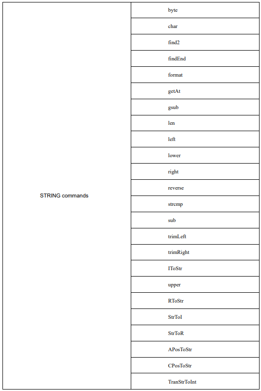
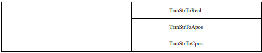
byte
Take the ASCCII code of the character in the nth position of the string.
Parameter 1: The variable or constant of string type.
Parameter 2: The variable or constant of type int.
Function return value: The int-type constant.
char
Return the character corresponding to the ASCCII code.
Parameter 1: The variable or constant of type int.
Function return value: The constant of string type.
find2
Return the position of the substring in the string.
Parameter 1: The variable or constant of string type.
Parameter 2: The variable or constant of type int.
Function return value: The int-type constant. (The return value is -1 when the corresponding character or string is not found)
findEnd
The string inversion lookup command, which locates the last occurrence of a specified string in a string and returns the index number.
Parameter 1: The source string to be looked up, a variable or constant of type string.
Parameter 2: The specified string to be looked up, a variable or constant of type string.
Return value: The index number of the search, a variable of type int.
format
The formatted STRING command, which transmits a reasonable formatting control in parameter 1, fills this formatting control with any number of subsequent parameters, and returns the filled data.
Parameter 1: The String format, a variable or constant of type string.
Parameter 2: The parameter of the formatting controller to be filled, a variable or constant of type string/real/int.
Parameter 3: The parameter of the formatting controller to be filled, a variable or constant of type string/real/int.
... (no limit on the number of parameters, as long as the total length does not exceed the length of a single commanded string)
Function return value: The count of successfully split and saved to an array, a variable of type int
The formatted string starts with % and supports the following uses.
%c - accepts a number and converts it to the corresponding character in the ASCII table
%d, %i - accepts a number and converts it into signed integer format
%o - accepts a number and converts it to octal format
%u - accepts a number and converts it to unsigned integer format
%x - accepts a number and converts it to hexadecimal format, using the lowercase letter x
%X - accepts a number and converts it to hexadecimal format, using an uppercase X
%f - accepts a number and converts it to floating point format
%s - accepts a string and formats it according to the given parameters
Example:
format("%%c: %c", 83) Output S
format("%+d", 17.0) Output +17
format("%05d", 17) Output 00017
format("%o", 17) Output 21
format("%u", 3.14) Output 3
format("%x", 13) Output d
format("%X", 13) Output D
format("%6.3f", 13) Output 13.000
format("%s", "monkey") Output monkey
format("%10s", "monkey") Output monkey
getAt
The command to obtain a single string. It gets the string data of a certain bit and returns the obtained data.
Parameter 1: The string to be intercepted, a variable or constant of type string.
Parameter 2: The position to be intercepted, a variable or constant of type int.
Function return value: The acquired string, a variable of type string.
gsub
Search for substring a within string s and replace a with string b.
Parameter 1: The variable or constant of string type.
Parameter 2: The variable or constant of string type.
Parameter 3: The variable or constant of string type.
Function return value: The constant of string type.
len
Calculate the length of a string.
Parameter 1: The variable or constant of string type.
Function return value: The int-type constant.
left
The command to take the left of a string. It intercepts a specified number of strings starting from the left side of the string and returns the intercepted data.
Parameter 1: The string to be intercepted, a variable or constant of type string.
Parameter 2: The number to be intercepted, a variable or constant of type int.
Function return value: The intercepted string, a variable of type string.
lower
Return the string in lowercase format.
Parameter 1: The variable or constant of string type.
Function return value: The constant of string type.
right
The command to take the right of a string. It intercepts a specified number of strings starting from the right side of the string and returns the intercepted data.
Parameter 1: The string to be intercepted, a variable or constant of type string.
Parameter 2: The number to be intercepted, a variable or constant of type int.
Function return value: The intercepted string, a variable of type string. reverse
The string inversion command, which inverts the string and returns it.
Parameter 1: The string to be inverted, a variable or constant of type string.
Function return value: The string to be inverted, a string variable.
strcmp
The String comparison command. Under this command, the return value is the ASCII difference between the first different characters.
Parameter 1: The string data to be compared, a variable or constant of type string.
Parameter 2: The string data to be compared, a variable or constant of type string.
Function return value: The returned ASCII value, a variable of type int.
trimLeft
The command to trim the string by left. This command removes the spaces to the left of the string and returns the modified string data.
Parameter 1: String to be trimmed, a variable or constant of type string.
Function return value: The trimmed string, a variable of type string.
trimRight
The command to trim the string by right. This command removes the spaces to the right of the string and returns the modified string data.
Parameter 1: String to be trimmed, a variable or constant of type string.
Function return value: The trimmed string, a variable of type string.
upper
Return the string in uppercase format.
Parameter 1: The variable or constant of string type.
Function return value: The constant of string type.
IToStr
Integer data to STRING command. The command allows to convert integer data to string type data and return the converted string.
Parameter 1: The integer data to be converted, a variable or constant of type int.
Function return value: The converted string data, a variable of type string.
RToStr
REAL parameter to STRING command. The command allows to convert the real data to string type data and return the converted string.
Parameter 1: The real data to be converted, a variable or constant of type REAL.
Function return value: The converted string data, a variable of type string.
StrToI
The String to Integer command. This command converts string data to integer type data and returns the converted integer data.
Parameter 1: The string data to be converted, a variable or constant of type string.
Function return value: The converted integer data, a variable of type int.
StrToR
The String to REAL data command. This command converts string data to REAL type data and returns the converted real number.
Parameter 1: The string data to be converted, a variable or constant of type string.
Function return value: The real data to be converted, a variable of type REAL.
APosToStr
The APOS point data to STRING command. This command converts apos points into strings in the specified format and returns the converted string data. The converted apos point is in the format "0; 1,2,3,4,5,6,0,0,0,0,0,0,0,0,0,0,0;", where the semicolon in front represents the apos point type and coordinate value, respectively.
Parameter 1: The APOS point data to be converted, a variable of type APOS.
Function return value: The converted string data, a variable of type string.
CPosToStr
The CPOS point data to STRING command. This command converts cpos points into strings in the specified format and returns the converted string data. The converted cpos point is in the format "1;0,0,0,0,0,0;1,2,3,4,5,6,0,0,0,0,0,0,0,0,0,0;", where the semicolon in front represents the cpos point type, cfg parameter and coordinate value, respectively.
Parameter 1: The CPOS point data to be converted, a variable of type CPOS.
Function return value: The converted string data, a variable of type string.
TranStrToInt
The command to get integer string array. This command splits the string according to the passed split character, converts the split value to an integer one-dimensional array and returns the number of valid splits.
Parameter 1: The string to be split, a variable or constant of type string.
Parameter 2: The separator, a variable or constant of type string.
Parameter 3: The split integer being stored as an array, a variable of type IntOneArray.
Function return value: The count of successfully split and saved to an array, a variable of type int
Example:
P:INT0.value = TranStrToInt("1_2_3er", "_", G:IntOneArray0) // The command passes in the character "1_2_3er", and after execution the system extracts the data by splitting it according to the incoming split character _. The split data is stored in the one-dimensional integer array variable IntOneArray0 in the order of 1, 2, 0, and the number of splits 3 is assigned to INT0.value.
TranStrToReal
A command to get an array of REAL strings. This command splits the strings according to the passed splitters and converts the split values into a REAL one-dimensional array and returns the number of valid splits.
Parameter 1: The string to be split, a variable or constant of type string.
Parameter 2: The separator, a variable or constant of type string.
Parameter 3: Store the split REAL type variable as an array, a variable of type RealOneArray.
Function return value: The count of successfully split and saved to an array, a variable of type int
Example:
P:INT0.value = TranStrToReal("1.1_2.2_3er", "_", G:IntOneArray0) // The command passes in the character "1.1_2.2_3er", after execution the system extracts the data by splitting it according to the incoming split character _. The split data is stored in the one -dimensional integer array variable RealOneArray0 in the order of 1.1, 2.2, 0 respectively, and the number of splits 3 is assigned to INT0.value.
TranStrToApos
The command to get an array of apos point data strings. This command splits the string according to the passed split character and converts the split value to an apos point variable, while returning a status of whether the conversion was successful or not. The string to be converted must be in the format "0; 1,2,3,4,5,6,0,0,0,0,0,0,0,0,0,0,0;", where the leading semicolon represents the apos point type, the coordinate value, and the last semicolon can be followed by any string.
Parameter 1: The string to be split, a variable or constant of type string.
Parameter 2: The separator, a variable or constant of type string.
Parameter 3: Store the split apos point data as an apos variable, a variable of type APOS.
Function return value: Return the status of the extraction success or failure, a variable of type int
Example:
P:INT0.value = TranStrToApos("0; 21,22,23,24,25,26,0,0,0,0,0,0,0,0,0,0;$qwqewe", "$", G: P0) // The command passes in the characters "0;21,22,23,24,25,26,0,0,0,0,0,0,0,0,0,0,0,0;$qwqewe". After execution, the system will split the extracted data according to the incoming separator $, and the data after $ will be discarded.
The split data are stored in the order 21, 22, 23, 24, 25, 26... in the order of a1, a2, a3, a4, a5, a6... of P0. and the successful return value 0 is assigned to INT0.value.
TranStrToCpos
The command to get an array of cpos point data strings. This command splits the string according to the incoming separator and converts the split value to an apos point variable, while returning a status of whether the conversion was successful or not. The string to be converted must be in the format "1;0,0,0,0,0,0,0;1,2,3,4,5,6,0,0,0,0,0,0,0,0,0,0,0,0;", with the semicolon preceding the cpos point type, the cfg parameter, and the coordinate value respectively.
Parameter 1: The string to be split, a variable or constant of type string.
Parameter 2: The separator, a variable or constant of type string.
Parameter 3: Store the split apos point data as a cpos variable, a variable of type CPOS.
Function return value: Return the status of the extraction success or failure, a variable of type int
Example:
P:INT0.value = TranStrToCpos("1;0,0,0,0,0,0;21,22,23,24,25,26,0,0,0,0,0,0,0,0,0,0;$qwqewe", "$", G: P0) //
The command passes in the characters "0; 0,0,0,0,0,0,0;21,22,23,24,25,26,0,0,0,0,0,0,0,0,0,0,0,0,0,0;$qwqewe".
After execution, the system will split the extracted data according to the passed splitting character $, the data after $ will be discarded. The data after the first ";" will be stored in the cfg parameter in the order of "0,0,0,0,0,0" and the data after the second ";" will be stored in the order of 21, 22, 23, 24, 25, 26... in the order of x, y, z, a, b, c... of P0, and the successful return value 0 is assigned to INT0.value.
3.19 ModbusTCP commands
The list of ModbusTCP commands:

GetModConState
This command is used to get the status of the robots connection to the external world using ModbusTCP communication. The command parameters are described as below:
GetModConState IsConnected
IsConnected: Connection status (Is Connected)
Data type: BOOL variable
Meaning: Return the current connection status.
For example1:

ReadModbusReg
The command is used to read the value of a specified Modbus register. The command parameters are described as below:
ReadModbusRegRegisterID RegisterValue
RegisterID: Target Modbus Register ID
Data type: int, with a value range of 101 to 1500.
Meaning: The ID number of the register to be read.
RegisterValue: Target Modbus Register Value
Data type: INT variable
Meaning: Return the value of the register after reading.
For example1:

WriteModbusReg
The command is used to set the value of a specified Modbus register. The command parameters are described as below:
WriteModbusReg RegisterIDRegisterValue
RegisterID: Target Modbus Register ID
Data type: int, with a value range of 101 to 1500.
Meaning: The ID number of the register to be modified.
RegisterValue: Target Modbus Register Value
Data type: INT variable
Meaning: The value of the register to be modified.
For example1:

3.20 Online payload identification command
List of the online payload identification command:

StartMdlLog
The online payload identification command. It is used to collect the robot motion data required for payload identification of the robot. The command parameters are described as below:
StartMdlLog dataType
dataType: Data storage type (Data type)
Data type: enum(Robot/WithLoad/ValidData)
Meaning: Data storage type.
− Robot: Collect the motion data of the robot body, that is, when no load is installed.
WithLoad: Collect the robot motion data when the robot is installed with a load at the flange.
− Used for applications where model accuracy verification is required, to collect the robot motion data when the robot is installed with a load.
Note:
Note: 1. The "WithLoad" data type is mandatory for collection, while "Robot" and "ValidData" data types are optional.
2. Using "Robot" data type for tuning improves the accuracy but increases the tuning computation time.
3. Using "ValidData" data type allows simultaneous model accuracy verification during tuning but increases the computation time.
4. For load tuning data collection, when selecting "Robot" or "WithLoad" as the Data type, the motion commands for tuning path should be MovJ. For "ValidData" type, the tuning path can use a combination of MovJ, MovL, MovC, and other commands.
StopMdlLog
The online payload identification stopping command. This command is used to conclude the collection of robot motion data for load tuning and automatically save the data.
Note: This command must be used in conjunction with the "StartMdlLog" command.
For example1:

CalcDynMdl
This command is used to perform tuning calculations on the previously collected robot payload information and store the computed results in the corresponding variables. The command parameters are described as below:
CalcDynMdl mdlType Tool Payload dataStepPer validEnable
mdlType: Identified model type
Data type: enum(TypeTool/TypePayload)
Meaning: The identified model type.
− TypeTool: Use for identification of tool parameters.
− TypePayload: Use for identification of payload parameters.
Tool: Tool variable (TOOL)
Data type: TOOL variable
Meaning: To save the identification results. It is only effective when the model type for identification is selected as TypeTool.
Payload: Workpiece load variable (PAYLOAD)
Data type: PAYLOAD variable
Meaning: To save the identification results. It is only effective when the model type for identification is selected as TypePayload.
dataStepPer: Data interval length (Identify the percentage of data extraction length)
Data type: int
Meaning: Extract valid identification data from the raw data. A greater value indicates a grater interval, resulting in fewer data points used for identification. As a result, the accuracy of the payload identification results may be lower. The valid range for this parameter is from 0 to 100.
validEnable: If it is model validation
Data type: enum(Enable/Disable)
Meaning: Enable or disable model validation during payload identification.
− Enable: Enable model validation.
− Disable: Disable model validation.
For example1:

No comments to display
No comments to display