
6. CALIBRATING
6.1. INTRODUCTION
Calibration associates the angle of each robot axis with the pulse count value supplied from the absolute Pulsecoder connected to the corresponding axis motor. To be specific, calibration is an operation for obtaining the pulse count value, corresponding to the zero position.
Calibration is factory-performed. It is unnecessary to perform calibration in daily operation. However, calibration becomes necessary after:
Motor replacement
Pulsecoder replacement
Reducer replacement
Cable replacement
Backup batteries for pulse count in the mechanical unit has run out

6.2. QUICK ZERO POSITION CALIBATION
Quick zero calibration is performed at factory with all loads uninstalled using special apparatus. Based on the robot parameter, this method provides the most precise zero position calibration.
Quick zero position calibration can reload zero position data that stored in the controller, when zero position data lost due to electrical or software faults. If the zero position data lost due to disassembly or maintenance, this method cannot be used.
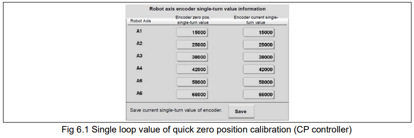
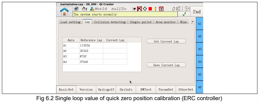
ESTUN robot uses encoder data as an auxiliary of calibration. Procedures are shown below.
a) Jog the robot manually to the place where the calibration marks are align.
b) Display the encoder information screen. Jog the axis at a low speed to make the real single loop value close to the reference value.
c) Calibrate the zero position of the axis. Create a new program, then create a new instruction “RefRobotAxis”, and run it.
6.3. MECHANICAL ZERO POSITION CALIBRATION
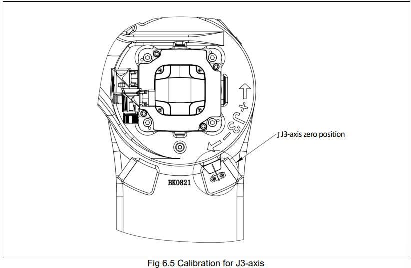
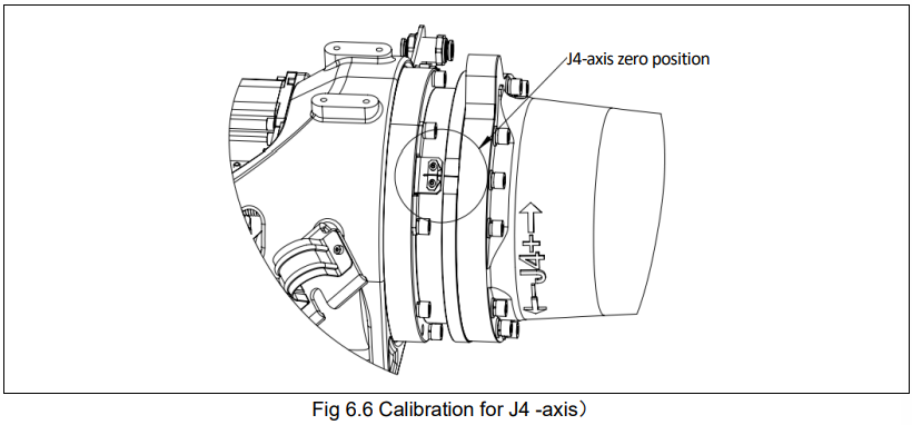
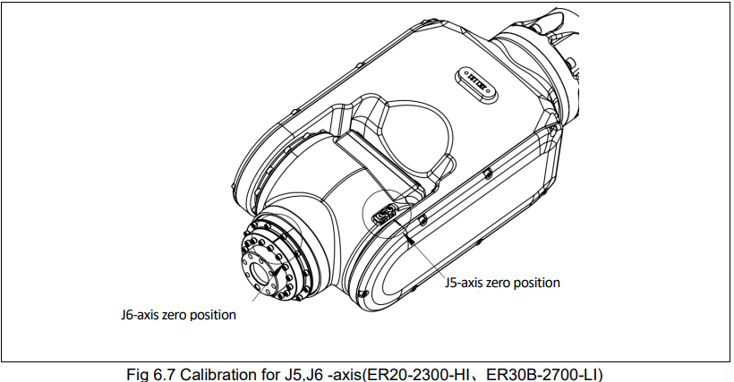
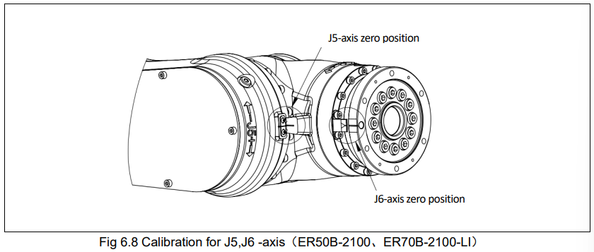
Mechanical disassembly or maintenance may cause zero position data lost. Mechanical zero position calibration is performed with all six axes jogged to zero-position by using their respective witness marks.
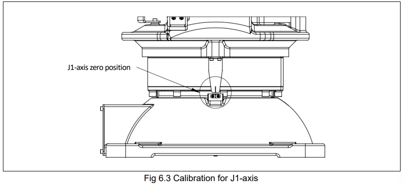
Take J1-axis for example of zero position calibration. As shown in the figure below, there are witness marks on the base and rotation base. Move the axis to align the marks as the procedures below.
a) Move J1-axis with teach pendant to align two witness marks.
b) Set this position as the zero position of J1-axis with the teach pendant.
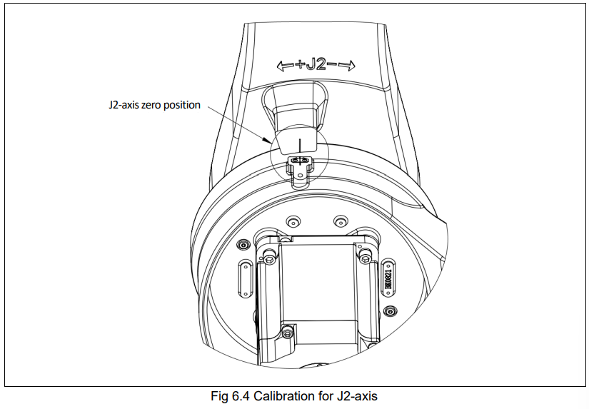
Perform calibration for each axis with procedures recommended above. If calibration for all axes has been performed and recorded, zero position for each axis can be set with teach pendant. Figures in this section are reference for calibration of other axes.
No comments to display
No comments to display