
1. Safety Precautions
This Chapter describes the content to be observed for the safe use of the robot. Before using, be sure to read and understand the content in this Chapter.
1. Before installation, operation, maintenance, and troubleshooting, it is essential to thoroughly read and fully understand this manual and other accompanying materials. Commence usage only after acquiring complete knowledge of the equipment, safety information, and precautions.
2. The terms "Danger", "Caution", and "Warning" used in this manual supplement safety considerations and do not represent an exhaustive list of all safety requirements that must be followed.
3. We will not assume any legal liability for personal safety incidents or property losses resulting from rule-breaking product operation.
4. Companies or individuals using ESTUN Robots should familiarize themselves with the standards and laws in their respective regions or countries. Additionally, appropriate safety measures should be installed to protect personnel using the robot.
1.1 Safety Symbols and Warning Signs
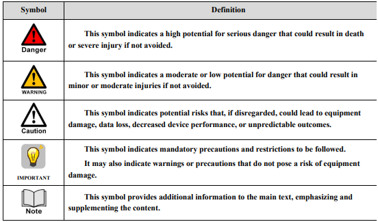
If the manual contains instructions marked as follows, users must read them carefully and follow strictly.
Safety Symbols
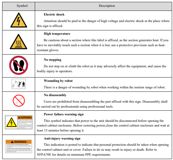
Warning and Caution Signs
1.2 Definition of Users
The users of this manual are defined as follows.
1. Operators
⚫ To perform the power ON/OFF operation of the robot;
⚫ To start the robot program from the operation panel;
⚫ To restore system alarm status;
⚫ To operate the E-stop button on the control cabinet and teach pendant in case of emergency.
⚫ Must not work inside the safety fence.
2. Programmers
⚫ To operate the robot;
⚫ To teach the robot outside the safety fence, etc.;
⚫ Teaching and working within the safety fence is only available in manual mode;
⚫ The above-mentioned personnel must receive specialized training on the robot.
3. Maintenance personnel
⚫ To operate the robot;
⚫ To teach the robot outside the safety fence, etc.;
⚫ To carry out the robot maintenance (repair, adjustment, replacement);
⚫ Teaching and working within the safety fence is only available in manual mode;
⚫ The above-mentioned personnel must receive specialist training on the robot.
The permissions of the users are listed in Table 1.1:
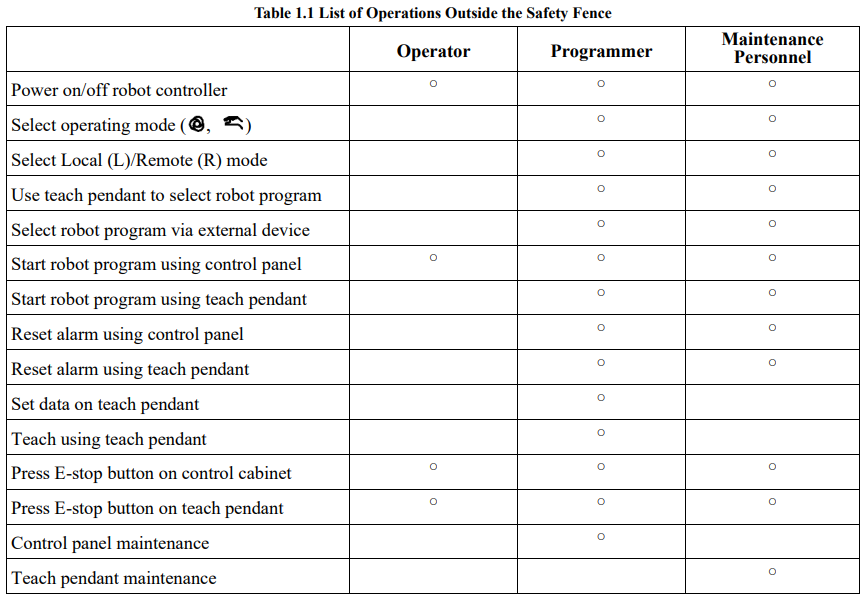
[Note] The table outlines the permissions of personnel working outside the safety fence. " " indicates tasks allowed for workers.
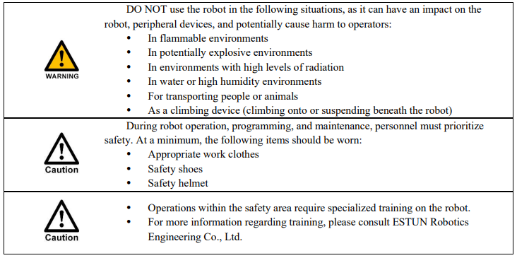
During robot operation, programming, and maintenance, personnel must prioritize safety. At a minimum, the following items should be worn:
Appropriate work clothes
Safety shoes
Safety helmet
1.3 Precautions for Users
1.3.1 Precautions for operators
1) Operators must handle robot power ON/OFF outside the safety fence and conduct pre-power checks, as outlined in "Section 5.1".
2) Operators should only use E-stop buttons on control cabinets and teach pendants in emergency situations.
1.3.2 Precautions for programmers
1) When teaching robot, programmers should preferably do so outside the safety fence;
2) When working outside the safety fence, teach pendants should be kept out of the robot's working area to avoid any unintended actions during robot movement;
3) If it's necessary to enter the safety fence, programmers must be in manual mode and follow the procedure for entering the safety fence (see " Procedure for entering the safety fence") before operating;
4) Programmers must carry teach pendants when entering the safety fence to prevent others from operating the robot without the user's knowledge;
5) During temporary robot stops, programming, or testing, the enable switch on the back of the teach pendant should be promptly turned off;
6) Ensure that the enable switch on the back of the teach pendant remains effective at all times.

1.3.3 Precautions for maintenance personnel
1) Pay attention to the parts in the robot that are prone to become hot
Some parts of the robot in normal operation will become hot, especially the servomotor and reducer, which may cause burns when being approached or touched. When it is inevitable, protective equipment such as heat-resistant gloves should be worn.

2) Safety precautions on removing parts
Ensure that the internal parts such as the gears are no longer rotating, and then you can open the lid or the protection device. You shall not open the protection device when the gears and bearings are rotating. If necessary, use the auxiliary device to make the internal unfixed parts remains its original position.
The initial test upon repair, installation and maintenance shall be carried out by following the steps below:
Clean up the robot and all maintenance and installation tools in the working space of the robot.
Install all the protective measures.
Power off the control cabinet.
Ensure that people are standing outside the safe range of the robot.
Pay special attention to the working conditions of the parts repaired during testing.
In case of robot repair, do not use the robot as a ladder, and do not climb on the robot to avoid falling.
3) Safety precautions on pneumatic/hydraulic components
After turning off the air source or hydraulic pump, a few residual gas or liquid exists in the pneumatic system or hydraulic system. Beware these gases or liquid, which have a certain energy; we must take some measures to prevent the residual energy from damaging to the human body and equipment.
Maintenance personnel must release any residual energy in the system before servicing pneumatic and hydraulic components.

4) When the maintenance or repair is carried, moreover, you should cut off other power supply connections.
5) Brake detection.
In general, the brake can be worn in the normal operation. Therefore, the brake detection is necessary by following the steps below.
a) Command the robot to move each joint within the safety enclosure to its maximum angle position;
b) Power off the robot control cabinet;
c) Once the robot has completely stopped, mark the positions of each joint.
d) After 2 hours, verify whether the marked positions of each joint have shifted from their original positions.
e) If any shifts have occurred, maintenance personnel need to replace the motor corresponding to the affected axis.
When add lubricating oil to the reducer, it might do harm to the person and the equipment. Therefore, you must obey the below safety information before adding lubricating oil:
a) Wear the protective measures (e.g. gloves, etc.) when refueling or draining oil to prevent damage to maintenance personnel caused by high-temperature oil or reducer.
b) Be cautious when opening the oil chamber cover. Keep away from the opening as there may be pressure in the oil chamber to cause splashing.
c) Oil filling shall be made according to the fuel gauge, which shall be not too full. Check the oil
indicator port after oil filling.
d) Oil of different designations cannot be added to the same reducer, and the remaining oil must be
cleaned up before using the oil of different designation.
e) Drain the oil completely or check the oil indicator port after oil filling.

1.4 Safety Precautions for Robot
1.4.1 General considerations
1.4.2 Installation precautions
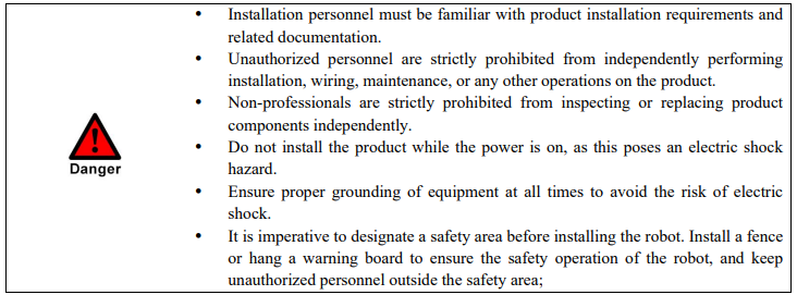
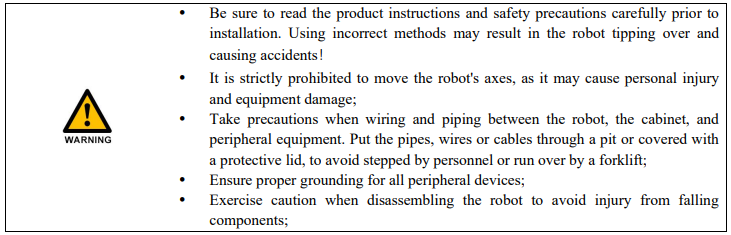
1.4.3 Precautions for operation
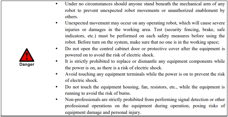
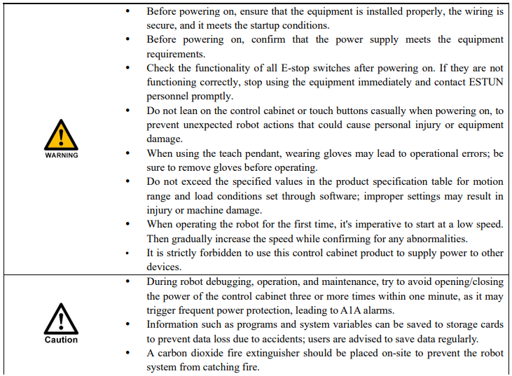
1.4.4 Maintenance precautions
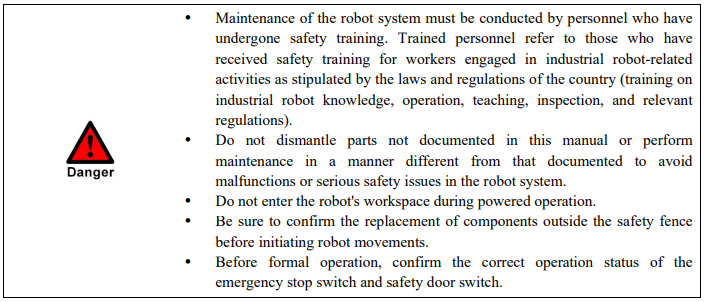
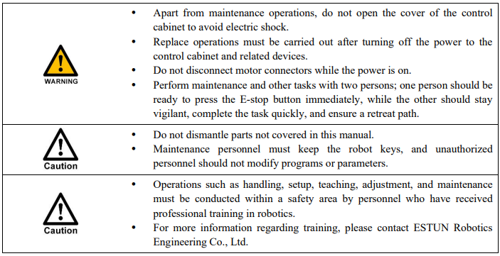
Before performing maintenance, maintenance personnel is required to carefully read the following content and fully understand the methods of safe maintenance.
1.5 Robot Stop Types
The safety function series control cabinet of ESTUN Robotics has the following 3 stop methods:
1.5.1 Power-off stop (compliant with Type 0 in IEC 60204-1)
The power-off stop disconnects the motor power source, resulting in an instantaneous robot stop. Due to the uncontrolled deceleration trajectory when the motor's power source is disconnected during robot motion, the control cabinet executes the following procedure:
Issues an alarm and cuts off the motor's power source to cause an immediate halt in motor rotation;
Pauses the program execution to make an instantaneous stop in the robot's motion.

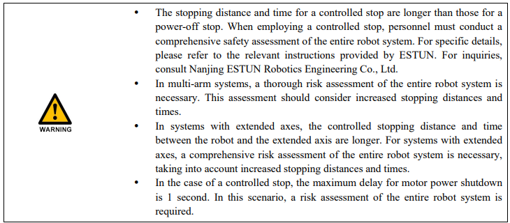
1.5.2 Controlled stop (compliant with Type 1 in IEC 60204-1)
The controlled stop is a robot stopping method where, following an alarm issued by the robot system, the robot's motion is gradually decelerated and stopped through control commands. The control cabinet executes the following procedure:
The robot system issues an alarm due to overload, failure, etc.;
The controller system issues a "controlled stop" command to decelerate and stop the robot's movement, pausing program execution;
Triggers the safety STO (Safe Torque Off) function of the servo.
1.5.3 Hold (compliant with Type 2 in IEC 60204-1)
"Hold" refers to a robot stopping method where power continues to be supplied to the motor after a controlled stop without triggering the safety STO function of the servo, allowing the robot's motion to gradually decelerate and stop.
The control cabinet executes the following procedure:
The robot operation is decelerated until it stops. Execution of the program is paused.
1.6 Security Category

1.7 Emergency Stop
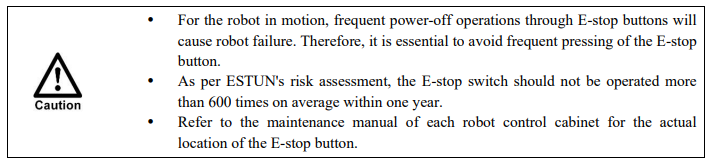
ESTUN robots feature the following E-stop devices:
E-stop buttons (located on the control cabinet and teach pendant).
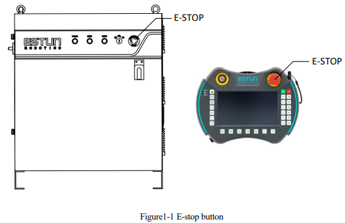
When the E-stop button is pressed, the robot comes to an immediate stop. External E-stop input signals are generated by the E-stop button, to enable the instantaneous halt of all robot movements by cutting off the motor's power source.
Safety Stop Function (external emergency stop function in SAFETY IO)
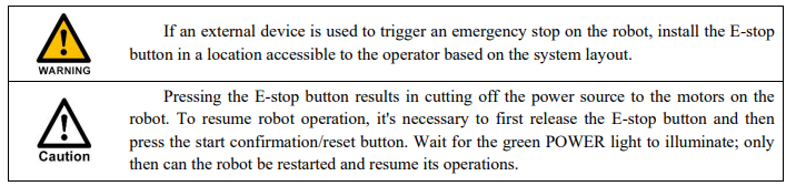
The external E-stop interface in SAFETY IO is initially shipped with a shorting jumper inserted. When using this function, turn the mode selector switch to manual mode before removing the shorting jumper. Follow the wiring instructions (see "4.8.2 External emergency stop wiring method") for proper connection. If not using this function, do not remove the shorting jumper to prevent triggering related functions that may result in the robot being unable to operate or triggering alarms.
1.8 Operations within the Safety Fence
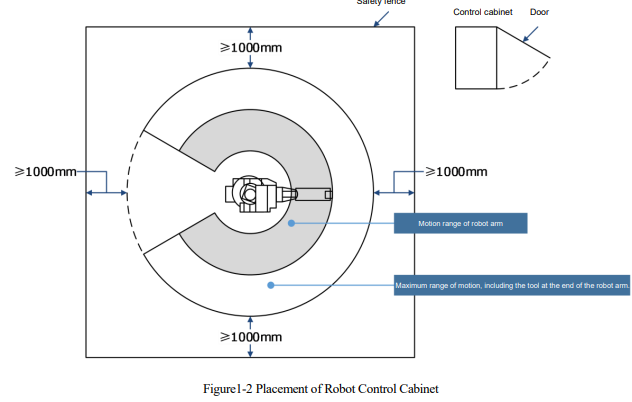
The control cabinet should be installed outside the range of robot movement (within a safety fence), as shown in Figure 1.2 below.
1.8.1 Safety fences and other safety measures
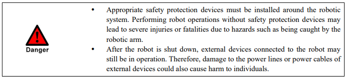
ESTUN Robotics is not an expert in safety systems, safety devices, or specific workplace safety. The purchaser or user of ESTUN robots is responsible for implementing necessary safety measures to ensure the safety of all individuals in the workplace.
Safety measures include, but are not limited to:
Safety Fences (Fixed Protective Devices)
Requirements for the safety fences include but are not limited to:
1) The construction of the fence must withstand foreseeable operational and environmental forces.
2) The fence must not have sharp edges or protrusions that pose a danger.
3) The fence prevents access to the protected space unless through openings equipped with interlocking devices or presence sensing devices.
4) The fence must be permanently fixed in the appropriate position and can only be dismantled with tools.
5) The fixing system of the safety fence must remain connected to the safety fence or the robotic system when being dismantled.
6) Where possible, the safety fence must be fixed in a given position and not movable.
7) The fence must minimize obstruction to the sight of the production process (e.g., wire mesh, grating, or panel fences).
8) The fence must maintain sufficient distance from the robot's maximum space.
9) The fence should be grounded (connected to protective earth) to prevent electric shock.
Safety Doors (Equipped with Interlocking Devices)
Requirements for safety doors include but are not limited to:
1) Safety doors (equipped with interlocking devices) shall be designed to prevent the automatic operation of the robotic system. If the safety door is mistakenly opened during the operation of the robotic system, the interlocking protective device will issue a stop or emergency stop command, immediately halting the robot's actions.
2) Safety door interlocks must be provided with plugs and sockets for interlocking. Users must select appropriate plugs and sockets for safety.
3) The drive of safety doors (equipped with interlocking devices) installed to prevent hazards should not create additional dangers (e.g., releasing harmful substances into the workspace).
4) Safety plugs and sockets.

Other Protective Devices
1.8.2 Procedure for entering the safety fence
Precondition: The robot is in motion, and programmers or maintenance personnel need to enter the safety fence to retrieve items.
1 Press the [STOP] button on the teach pendant, wait for the robot to come to a complete stop.
2 After the robot has fully stopped, press the E-stop button or use the external stop function on SAFETY IO to cut off the power source to the motors. Ensure the robot has completely stopped before entering the safety fence.
3 Ensure that there is accompanying personnel outside the safety fence near the E-stop button of control cabinet in case of any unexpected events.
4 To resume the robot's motion, exit the safety fence, restore the emergency stop button or external stop function, then press the start confirmation/reset button. Wait for the power source to be supplied to the motors before resuming robot operations.
Precondition: Programmers or maintenance personnel need to enter the safety fence to perform teaching tasks.
1 Press the [STOP] button on the teach pendant, wait for the robot to come to a complete stop.
2 After the robot has fully stopped, set the mode selector switch on the control cabinet to manual mode. Enter the safety fence only after confirming the robot has completely stopped.
3 Follow the instructions on the teach pendant interface for teaching operations.
4 Ensure to carry the teach pendant at all times inside the safety fence to prevent unintended operations by others.
5 Ensure that there is accompanying personnel outside the safety fence near the E-stop button of control cabinet in case of any unexpected events.
6 To resume the robot's motion, exit the safety fence, switch back to automatic mode, then press the start confirmation/reset button before resuming robot operations.

1.8.3 Precautions for operations inside the safety fence
When programmers or maintenance personnel must enter the safety fence, the following points must be considered:
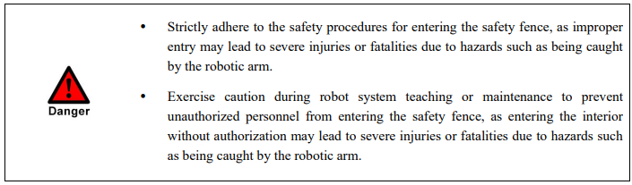
Before entering the safety fence, follow the " Procedure for entering the safety fence".
Ensure indicator LEDs display the robot's stopped status and enter the safety fence through the safety door.
Display "working" if informing others about working inside the safety fence. During robot teaching or testing operations, the robot may move unexpectedly, so personnel should be able to escape the robot's position and perform teaching tasks.
Ensure that, when operating inside the safety fence, the control cabinet is in manual mode, and the robot can only be operated by gripping the enable switch manually.
When multiple workers collaborate, the person in charge should be equipped with the teach pendant, and other workers must obey his or her commands.
Any operations from external interfaces and the robot controller panel without authorization are prohibited.
All workers inside the safety fence must always remain in the escape area to avoid dangers from unexpected robot movements.
Workers should avoid obstructing each other's escape routes.
Do not operate the robot when away from the operator's escape area.
Continuously observe the robot during jogging, program verification, and other operations.
If a danger is detected, immediately stop the robot using the E-stop button.
Other personnel near the E-stop button outside the safety fence should remain vigilant at all times.
After completing operations inside the safety fence, do not leave tools or equipment within the robot's or peripheral devices' range of motion.
1.9 Emergency Brake Release Procedure
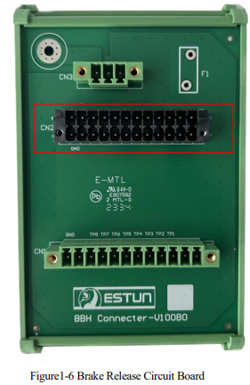
In situations where the robot poses a threat to personal safety, such as causing injury or trapping limbs, the authorized personnel holding the key can utilize the brake release device to urgently release the robot. Refer to Figure 1-3 for the brake release device.
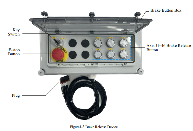
The break release device consists of a breakaway button box and an orange and black plug, in which the breakaway button box contains a key switch, an emergency stop switch, and breakaway buttons corresponding to the J1~J6 axes. The key switch is used to switch on the unlocking device, the unlocking buttons of the J1~J6 axes are used to unlock the corresponding axes, and the emergency stop button is used to restore the locking after the unlocking button is pressed.
: The steps for emergency brake release are as follows:
1) Press the [STOP] button on the demonstrator;
2) The user taps the emergency stop button on the cabinet and on the teach pendant to open the cabinet door;
3) For the J2 and J3 axes, after unlocking the holding brake, there is a risk of the robot tipping down.
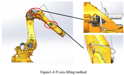
Therefore, it is necessary to bind the robotic arm by means of a lanyard for lifting and fixing to prevent the fall from causing injury to the machine;
⚫ J3 axis lifting method
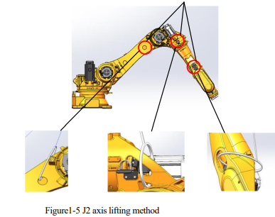
⚫ J2 axis lifting method
When the angle of J2 axis is less than 45°, the lifting method is the same as that of J3 axis.
When the angle of the J2 axis is greater than 45°, the lifting method is as follows
4) Restore the Emergency Stop button, then press the blue Start Confirm/Reset button and wait for the white POWER light to come on to provide a power source for the motor.
1) Open the transparent cover above the brake release button box, insert the key into the key slot, and switch from OFF to ON.
2) Select the axis for releasing the brake, press the corresponding brake release button for that axis to complete the brake release operation.
3) To urgently re-engage the brake, press the corresponding E-stop button on the brake release device.

No comments to display
No comments to display