
5. Debugging
5.1 Checks Before Power-ON
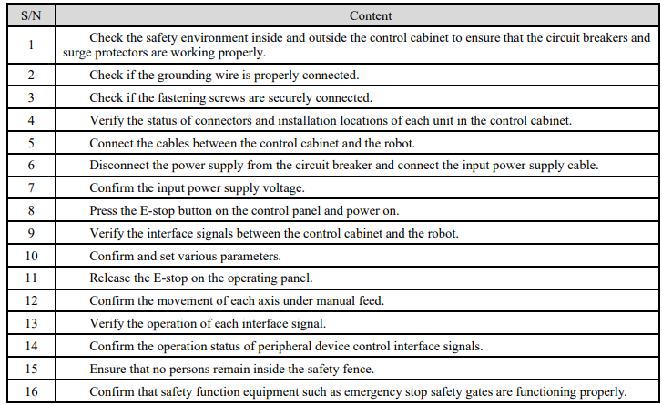
Before powering on the control cabinet, please check and confirm the following items, and make necessary adjustments if needed.
5.2 Control Cabinet Power-up Procedures
1) Ensure that no personnel are inside the safety fence.
2) Ensure the cabinet doors are closed; if not, do not power up.
3) Set the control cabinet mode selector switch to manual mode.
4) The operator rotates the load switch from OFF to ON, waits for the white POWER light to come on, waits for the teach pendant to be ready, and checks for any alarms on the interface. If there are no alarms, proceed to step (5); otherwise, follow step (6).
5) Under normal operating conditions, after the teach pendant is started, press the Blue Start Confirmation/Reset button. Provides a power source for the motor and triggers the safe STO function of the servo.
6) When the control cabinet is in an alarm state and the red alarm light is on, after the alarm problem is solved, press the blue Start Confirm/Reset button to provide the power source of the motor and trigger the safety STO function of the servo.
7) When the emergency stop is pressed in an emergency situation, if the power source of the motor is to be restored, it is necessary to restore the emergency stop and check that there are no alarms on the teach pendant before pressing the blue Start Confirmation/Reset button, which provides the power source of the motor and triggers the servo's Safe STO function.
5.3 Control Cabinet Power-off Procedures
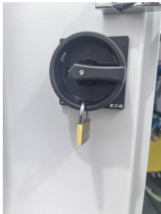
1) In the case of normal operation of the robot, the user first presses the "STOP" button on the demonstrator, and then presses the emergency stop button on the control cabinet after the robot has completely stopped, and then rotates the load switch from ON to OFF, observes that the white POWER light goes out, and then uses the lock to lock the load switch, and then finally opens the door of the cabinet with the key by the programmer or maintenance personnel;
2) When the control cabinet is in alarm, the control cabinet will trigger the safety STO function of the servo. The user only needs to rotate the load switch from ON to OFF, observe the white POWER light go out and use the lock to fasten the load switch, then the cabinet door will be opened by the programmer or maintenance personnel using the key;
3) In case of emergency, press the emergency stop or open the safety door, the control cabinet will cut off the power source of the motor immediately. The user only needs to rotate the load switch from ON to OFF, observe that the white POWER light goes out and then use the lock to fasten the load switch, and then the cabinet door will be opened by the programmer or maintenance personnel using the key.

5.4 Use of Teach Pendant
5.4.1 Teach pendant connection
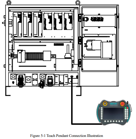
The Functional Safety Series Control Cabinets can be equipped with a teach pendant for robot teaching and programming. The connection is illustrated in Figure 5-1. For detailed operations, refer to the programming manual for the teach pendant.
5.4.2 Local/Remote selector switch
The local/remote selector switch is located in the upper-left corner of the teach pendant, where "L" stands for local, and "R" stands for remote. It is used for users to choose between local mode or remote mode. Only when the operator sets the teach pendant to local mode can they perform automatic mode and manual mode operations for mode selection on the control cabinet.
5.4.3 Editing method
The modification of drive unit parameters can be completed by following the steps below.
1) When the main power is turned on, the control cabinet undergoes an initialization diagnosis.
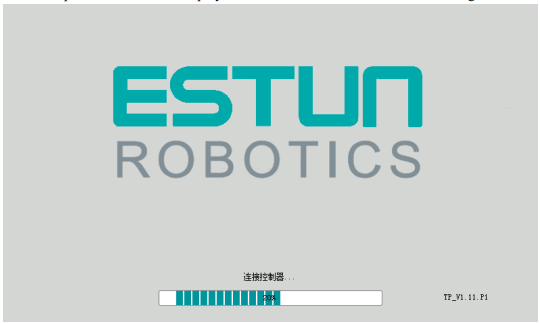
The teach pendant screen will display the initialization screen as shown in the figure below
2) After initialization is completed, check the system's operating status using the status indicator LEDs on the teach pendant. The Run indicator LED should be continuously on, and the Err indicator LED should be off, indicating a normal operating state
3) When the teach pendant displays the Home screen, select "General Settings > Servo Management".
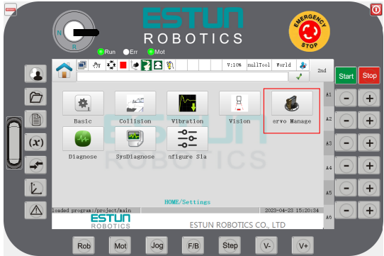
4) Select the "Set Pn Parameters" tab. When the teach pendant displays the "Set Pn Parameters" screen, choose the tab corresponding to the desired drive axis (e.g., Axis 1) and click the "Set" button.
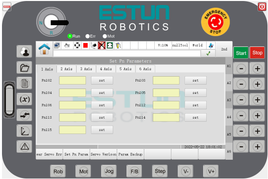
5) In the parameter dialog box that appears, set the desired parameters.

5.5 Mode Selector Switch
For the Functional Safety Robot Control Cabinets, the mode selector switch is located on the control cabinet panel, as depicted in the following figure.
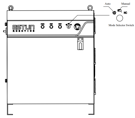
For the Functional Safety Series Control Cabinets, the mode selector switch is installed on the control cabinet panel. Users can choose the respective mode by using a key for the corresponding operations.
5.5.1 Operation modes
The operation modes include Auto Mode  and Manual Mode
 .

5.5.2 Enable switch
When in manual mode, users must hold the enable switch to allow robot movement. Users need to jog the "+"/"-" buttons on the right side of the teach pendant for respective axis operations. Note that in this mode, the robot moves at speeds less than 250mm/s.

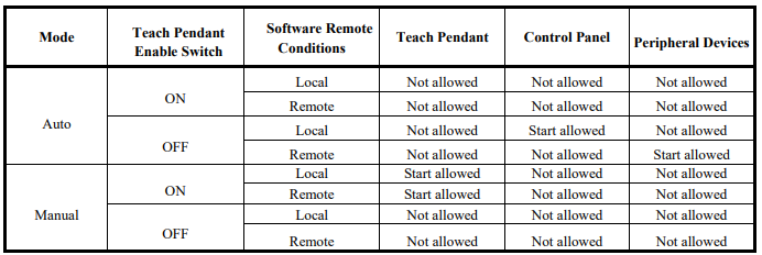
The effectiveness of signals sent by the teach pendant, control panel, and peripheral device interfaces will vary based on the mode selector switch on the control panel, the teach pendant enable switch, and the remote conditions set in the software, as indicated in the table below.
5.6 Use of ESView Software
5.6.1 Connecting the servo drive unit
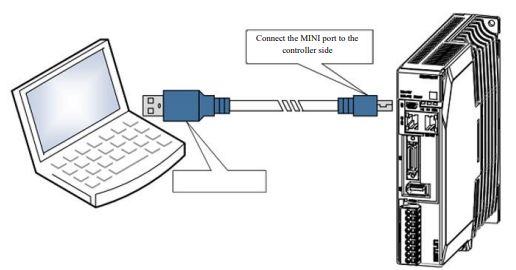
To perform online operations, connect the PC and the servo drive unit using a USB-RS485 (RJ45) communication cable.
Please follow the guided steps below to connect the servo drive unit.
⚫ Press the "Stop" button on the control cabinet to disconnect the main power.
⚫ Rotate the "ON" switch to "OFF" to disconnect the control power.
⚫ Contact the user who specialized in keeping keys to electrical cabinets to open the door of the control cabinet.
⚫ Check and wait for all indicators in the control cabinet to go out (usually at least 5 minutes).
⚫ Connect the PC to the servo drive unit using the USB-RS485 (RJ45) communication cable according to the following connection diagram.
Lift the interlock latch at the lower right corner, then rotate the switch from "OFF" to "ON" to power on the control.
At this point, the PC has successfully connected to the servo drive unit.
5.6.2 Installing ESView
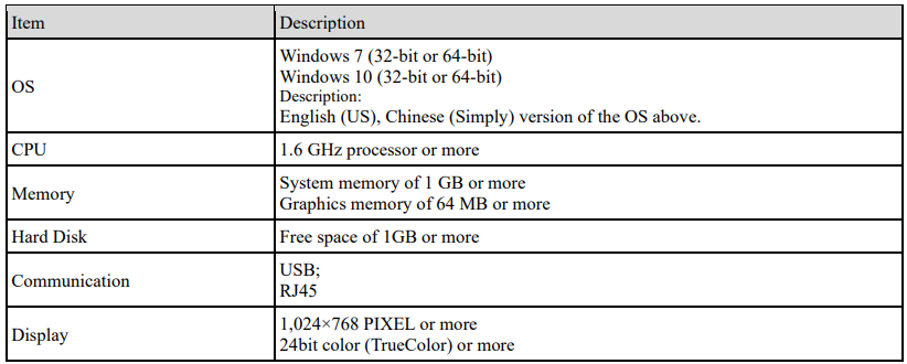
System Requirements
Users are required to have a personal computer that meets the following basic conditions.
Preparation
Please prepare the Windows operating system, communication cable, and a decompression software in advance.
Visit ESTUN official website www.estun.com to find and download ESView V4 on Technical Support >
Download for getting the compressed file. For help, please contact ESTUN.
Turn on the power supply of PC and start Windows. (Close down other software running.)
Copy ESView V4 compressed file into an appropriate folder.
Disconnect if the Drive is connected to the PC with the cable.
If you want to reinstall ESView V4, you should unload the previous ESView V4.
Install Software
Close other running software before installing the software and confirm that the Windows user has administrator privileges.
Step 1 Extract the ESView V4 compressed file in an appropriate directory of your PC.
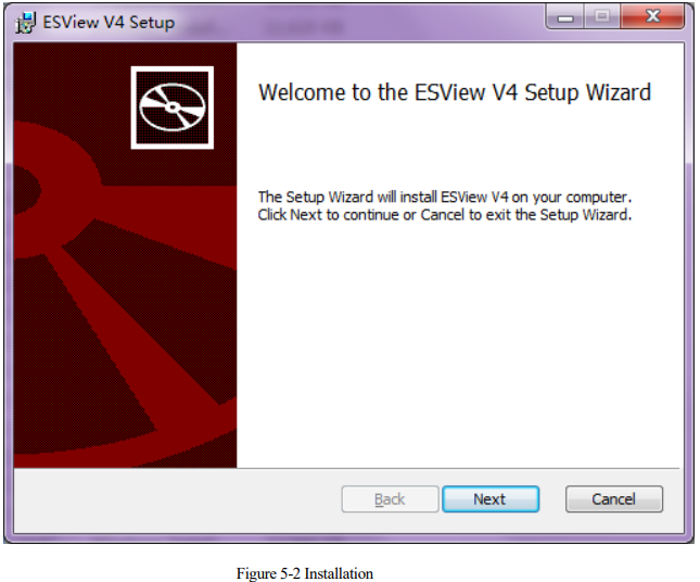
Step 2 Double click the ESView V4 installation program.
The installation program will automatically start, as shown in the following Figure
Step 3 Follow the instructions of the installation wizard to install ESView V4 to your PC
---- End
Install USB Driver
After installing the ESView V4 software successfully, you may also need to install the USB driver. If you have successfully installed a USB drive, you can skip what is described in this section.

Please follow the instructions below to install the USB driver.
Step 1 After installing the ESView V4 software successfully, connect the Drive to the PC by using the USB connection cable.
Step 2 Open the main directory of ESView V4 software (default location is C:\ESView V4\), and extract the USB Drivers.rar compressed file to an appropriate directory of your PC.
Step 3 Open Device Manager:
For Win7 OS, select Start > Control Panel
Click Device Manager on the displayed All Control Panel Items
For Win10 OS, just right-click Start, and select Device Manager on the pop-up menu.
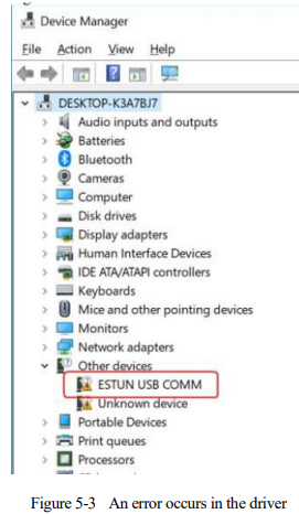
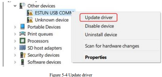
Step 4 An exclamatory mark attaches to the option Other devices > ESTUN USB COMM in Device
Manager window, which indicates an error occurs in the driver and needs to update, as shown in Figure.
Step 5 Right-click ESTUN USB COMM, and select Update driver on the pop-up menu.
Step 6 Click Browse my computer for driver software on the Update Drivers dialog box.
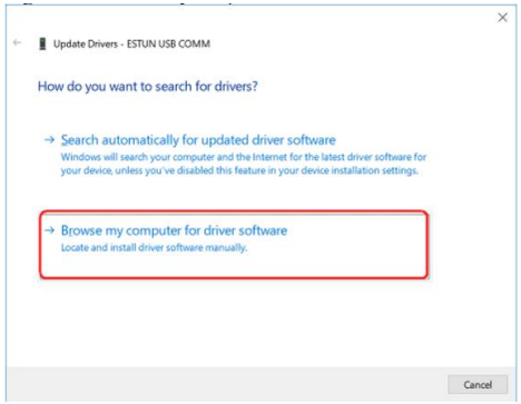
Figure 5-5 Browse my computer for driver software
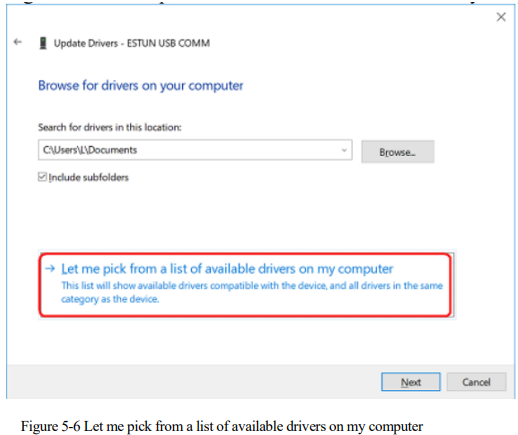
Step 7 Click Let me pick from a list of available drivers on my computer.
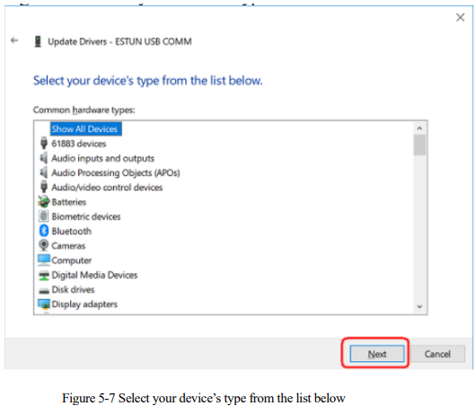
Step 8 Click Next.
Step 9 Click Have Disk.
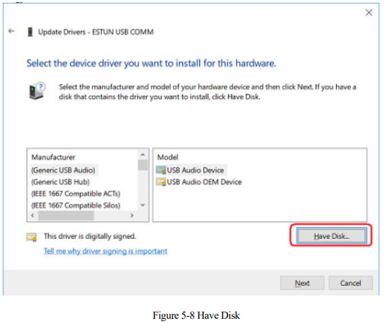
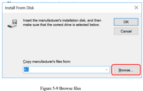
Step 10 Click Browse on the Install From Disk dialog box.
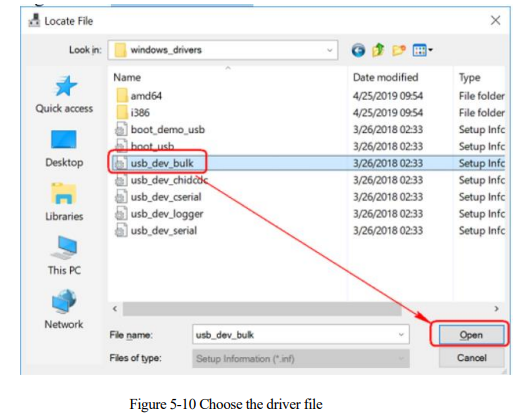
Step 11 Set the Look in as the directory of ESView V4 decompressed file \USB Drivers\windows_drivers on the Locate File dialog box.
Step 12 Choose usb_dev_bulk.inf, and then click Open.
Step 13 Click OK on the Install From Disk dialog box.
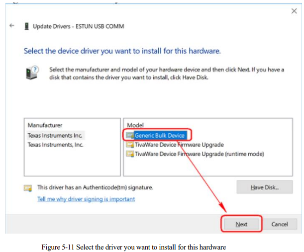
Step 14 Choose Generic Bulk Device, and then click Next.
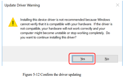
Step 15 Click Yes on the Update Driver Warning dialog box.
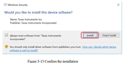
Step 16 Wait for a while, and then click Install on the Windows Security dialog box.
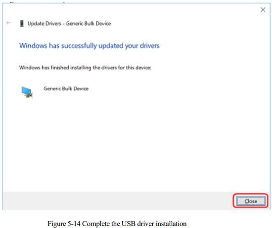
Step17 The driver will be automatically installed to your PC, and then the installation result will be displayed.
Click Close to complete the USB driver installation.
5.6.3 Enabling ESView
Online Operation
The parameters only can be written into or read from the Drive under the online operation. It is recommended that you perform an online operation for the first time to set the Drive.
You need to connect the Drive to the PC by using the USB connection cable before the online operation.
Step 1 Connect the Drive to the PC by using the USB connection cable.
Step 2 Select Programs > ESView V4 > ESView V4 from the Windows Start Menu.
Also, you can find and click ESView V4 shortcut on the desktop of Windows.
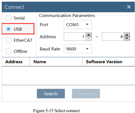
Step 3 The Connect dialog box will be displayed.
If you had started ESView V4, select Home > Connect in the Menu Bar
Step 4 Select USB.
Step 5 Click Search.
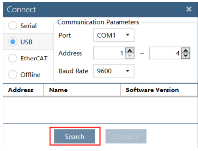
Figure 5-16 Search device
Step 6 Select the found device.
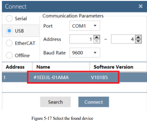
If the device is not found in "Search", please check the connection between the device and the PC and make sure that the software version of ESView V4 is up-to-date.
Step 7 Click Connect.
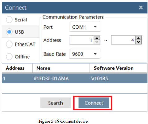
Step 8 The connected device will be displayed in the Device list on the left of the ESView V4 main windows.
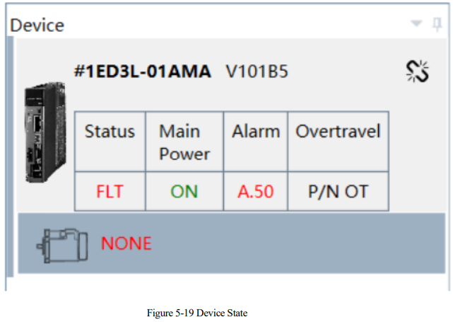
Now, you can make the necessary settings for the Drive or Motor in real time

----End
Offline Operation
In offline operation, users do not need to connect any equipment, can perform oscilloscope, FFT, mechanical analysis and other image operations.
Although it is not necessary to connect the actual drive, some functions are limited and cannot be set correctly.
Step 1 Select Programs > ESView V4 > ESView V4 from the Windows Start Menu.
Also, you can find and click ESView V4 shortcut on the desktop of Windows.
Step 2 The Connect dialog box will be displayed.
If you had started ESView V4, select Home > Connect in the Menu Bar.
Step 3 Select Offline.
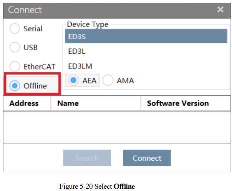
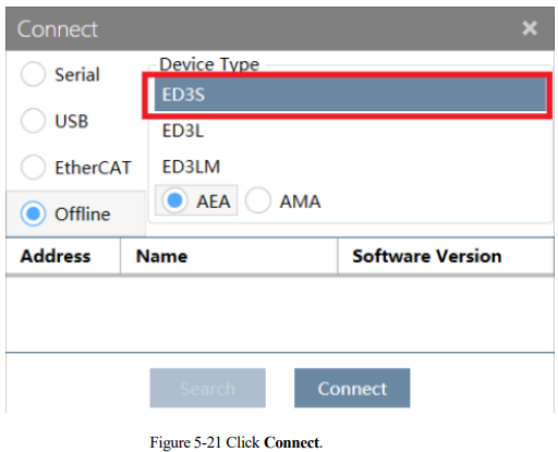
Step 4 Select the desired Device Type, e.g. ED3L
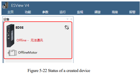
Step 5 The created device will be displayed in the Device list on the left of the ESView V4 main windows

5.6.4 Parameters settings
In the "Parameter Edit" window, users can perform the following operations:
Upload Parameters
Edit Parameters
Save Parameters
Download Parameters
Restore Factory Values
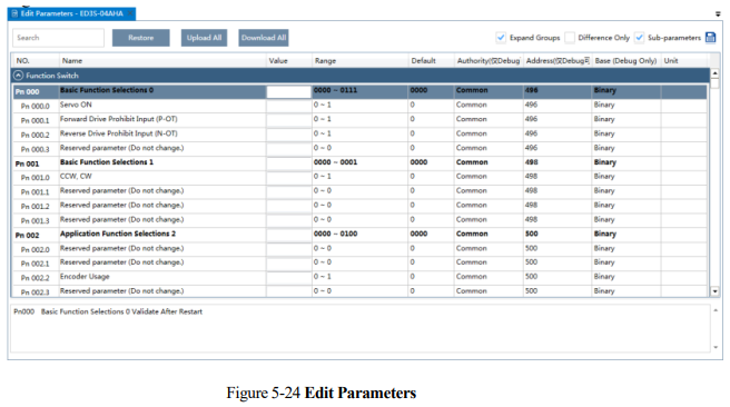
Follow the below procedure to open the Edit Parameters window.
Step1 Select Parameters > Edit Parameters in the Menu Bar of the ESView V4 main windows.
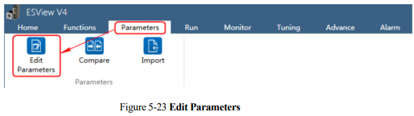
Step 2 The Edit Parameters window will be displayed in Function Display Area.
Upload Parameters
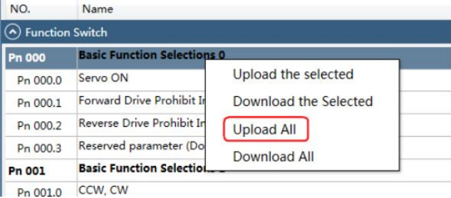
There are two ways to upload parameters: "Upload All" and "Upload Selected Items".
⚫ Upload All
− In the "Parameter Edit" window, click on "Upload All". Wait for a moment, and ESView V4 will read and retrieve all parameter settings from the drive. The retrieved parameters will be displayed in the "Device Values" column.

Right-click the parameters list where cannot be edited, and select Upload All in the pop-up menu.
⚫ Upload the Select
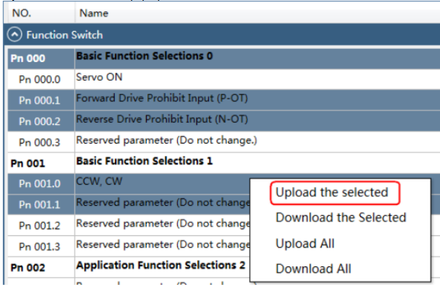
Drag the mouse to select the desired parameters on the Edit Parameters window, or you can hold Ctrl key and click the desired parameter, and then right-click a selected parameter, and select Upload the selected in the pop-up menu.

Modify Parameters
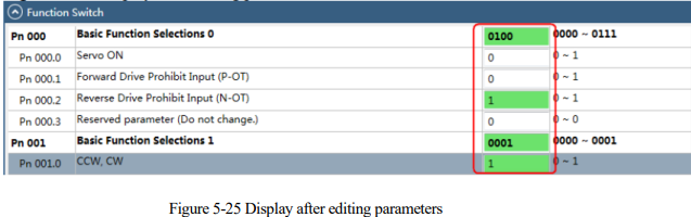
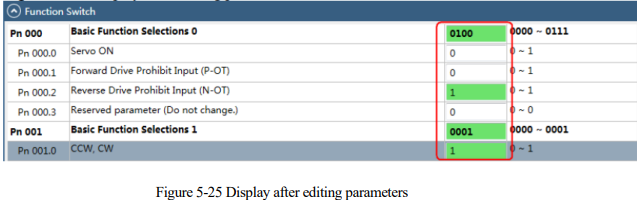
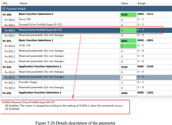
When the parameters have been uploaded from the device, you can modify them on the Value column. If a value has been modified, the background of the textbox can be changed.

Save Parameters
Operating steps
Follow the below procedure to save the current settings to the local path into the PC.
Step 1 Click  in the Edit Parameters window.

Step 2 Choose the desired files in the Save As dialog box.
Step 3 Click Save.
----End
Import Parameters
You can fulfill Import function, importing the offline parameters file into the online Drive.
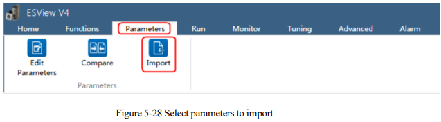
Step 1 Select Parameters > Import in the Menu Bar of the ESView V4 main windows.
Step 2 Select a proper offline parameter file (*.esvpa) in the pop-up Open dialog box.
Step 3 The Import window will be displayed in Function Display Area.
And, the parameter settings in the selected offline file are also displayed in the "Local Value" column.
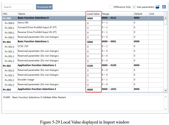
Step 4 Before importing parameters into the Drive, you can edit and download the parameters.
----End
Download Parameters
⚫ Download All
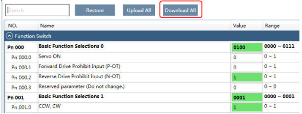
− Click Download All in the Edit Parameters window. After waiting for a moment, write the edited parameters to the drive.
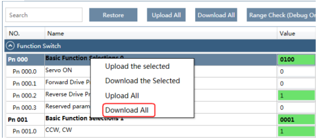
− Right-click the parameters list where cannot be edited, and select Download All in the pop-up menu.
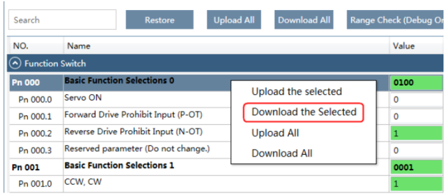
⚫ Download the Selected
Drag the mouse to select the desired parameters, or you can hold Ctrl key and click the desired parameter, and then right-click a selected parameter, and select Download the Selected in the pop-up menu.

Restore Factory Values

Step 1 Click Restore in the Edit Parameters window.
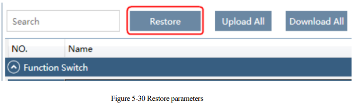
Step 2 After confirming the execution of "Restore", read the content on the warning dialog box and click OK.
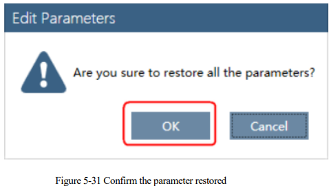
Step 3 ESView V4 will send the Restore Parameters command to the Drive, and then the Drive will execute the Restore Parameters.
----End
5.7 Definition of Parameters
5.7.1 Instructions for use
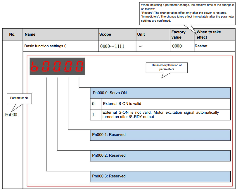
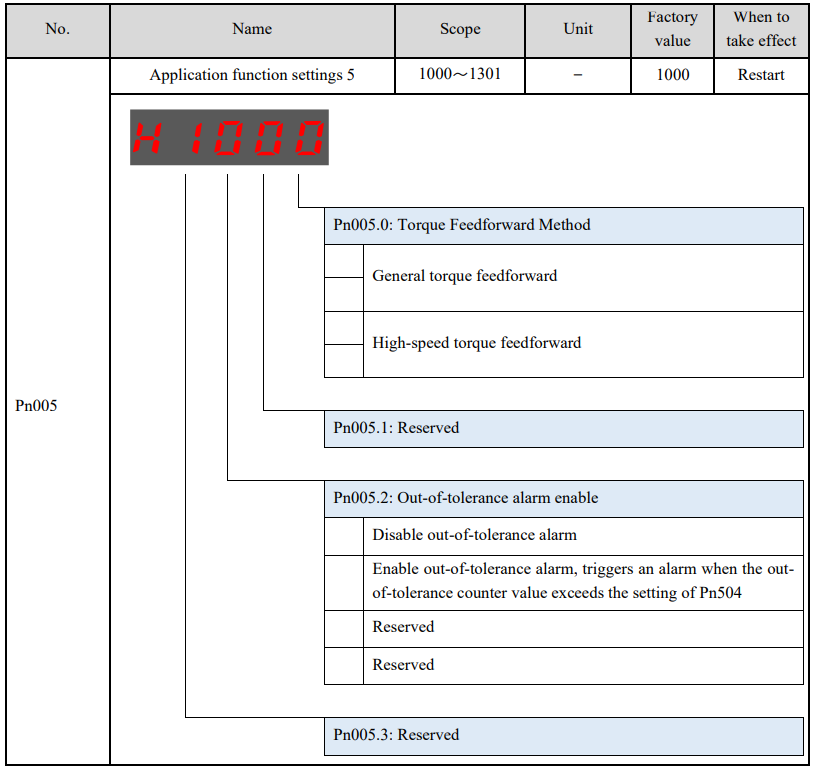
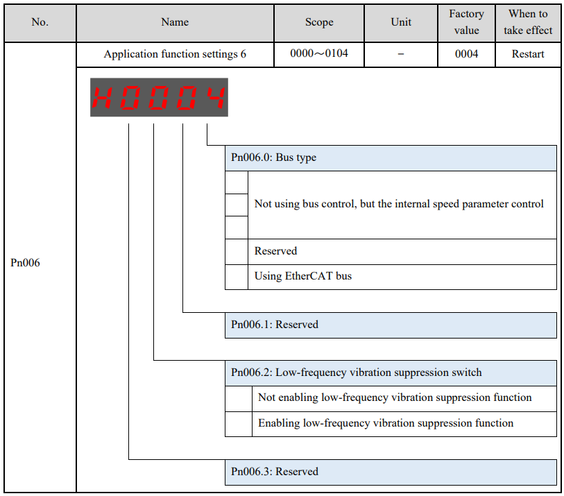
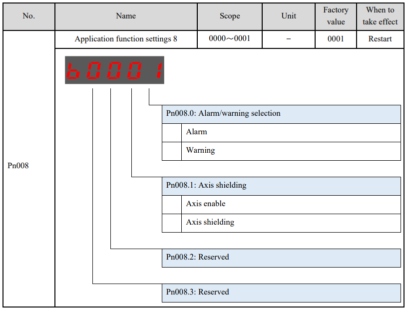
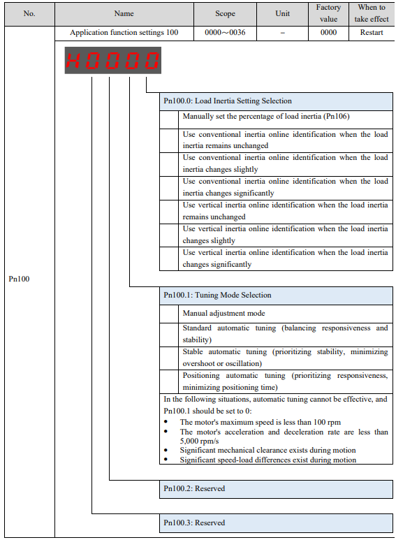
5.7.2 Detailed explanation of parameters
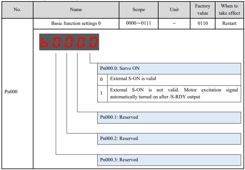
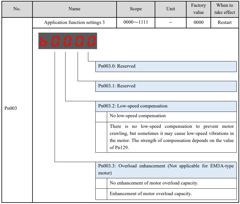
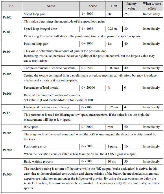
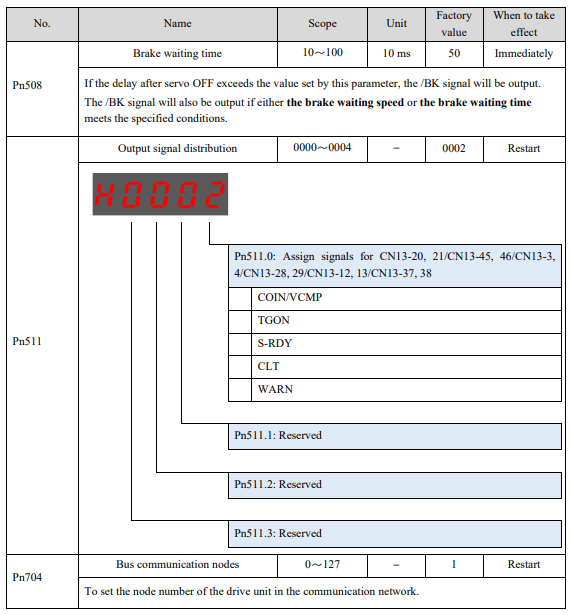
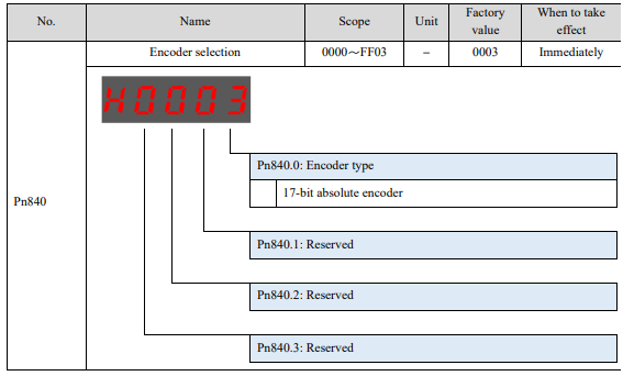
No comments to display
No comments to display