
8. I/O and Serial Port
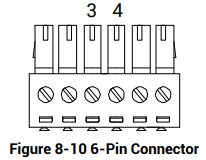
The device’s 6-pin connector has non-isolated input signal (LineIn1), non-isolated output signal (LineOut1), and one RS-232 serial port. This section introduces the I/O electrical feature and I/O wiring, as well as RS-232 serial port.
8.1 I/O Electrical Feature
This section introduces the electrical feature of input signal and output signal.
8.1.1 Input Signal
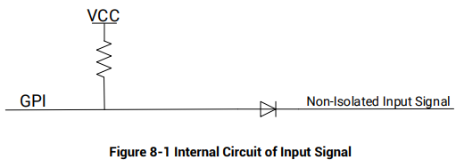
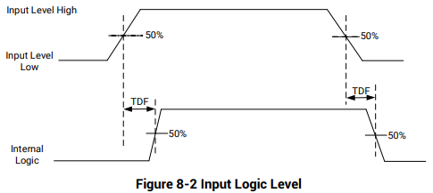
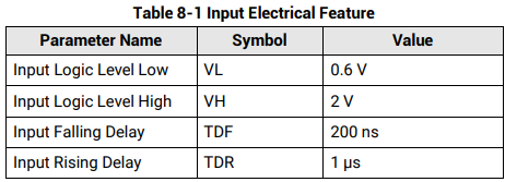
The device's LineIn1 is a non-isolated input signal, and the internal circuit shows below.

8.1.2 Output Signal
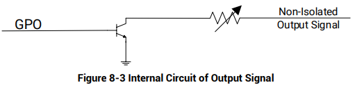
The device's LineOut1 is a non-isolated output signal, and the internal circuit shows below.
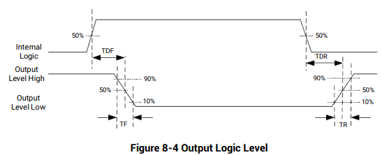
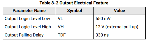
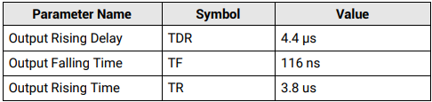
When the external voltage is 12 V, and the pull-up resistor is 1 KΩ, the output electrical feature is shown below.
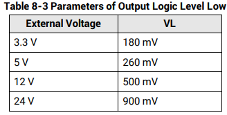
When the external voltage and resistor are different, the parameters of output logic level low are shown below.
8.2 I/O Wiring
This section introduces how to wire the I/O parts.
8.2.1 Input Signal Wiring

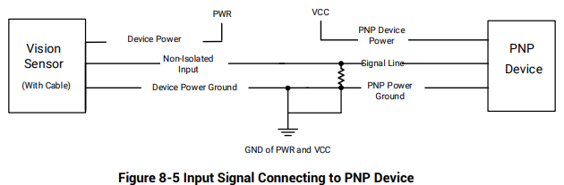
PNP Device
The pull-up resistor is connected to the device. A 1 KΩ pull-up resistor is recommended.

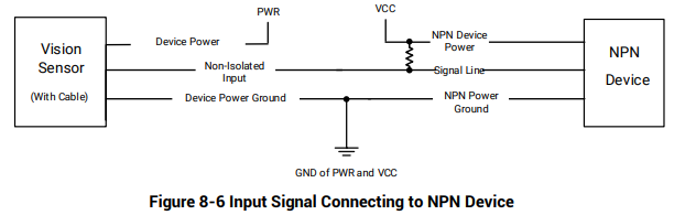
NPN Device
The pull-up resistor is connected to the device. A 1 KΩ pull-up resistor is recommended.
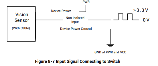
Switch
The switch provides low level for bi-directional I/O triggering.
8.2.2 Output Signal Wiring

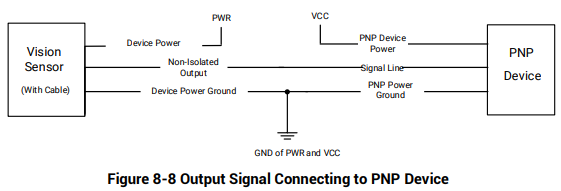
PNP Device
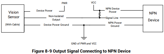
NPN Device
The pull-up resistor is connected to the device. A 1 KΩ pull-up resistor is recommended.
8.3 RS-232 Serial Port
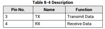
The device supports outputting via the RS-232 serial port. You can refer to the table below for the specific pin name and function.
No comments to display
No comments to display