
8. Functions
8.1 Feature Tree
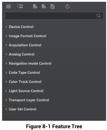
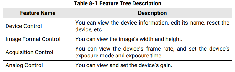
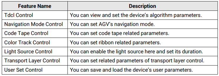
After selecting the device in the device list, right click it and select Feature Tree. You can view and set parameters of the device here.

8.2 Device Control

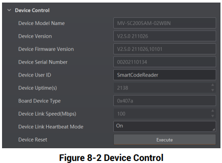
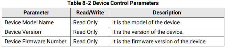
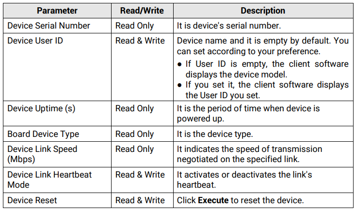
Go to Device Control, you can view device information, edit device name, reset device, etc. The specific parameters in Device Control are shown below.
8.3 Image Format Control
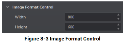
Go to Image Format Control, you can view the image’s width and height, as shown below.
8.4 Acquisition Control
8.4.1 Set Frame Rate
Frame rate refers to the image number that is acquired by the device per second. The higher frame rate, and shorter time used for image acquisition will be.
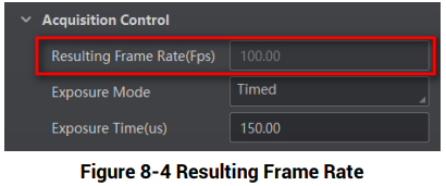
Go to Acquisition Control, you can view the device’s real-time frame rate in Resulting Frame Rate.
8.4.2 Set Exposure Time
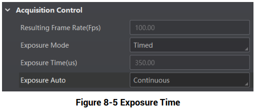
The device supports 3 types of auto exposure mode, including Off, Once and Continuous. Click Acquisition Control → Exposure Auto, and select the mode according to actual demands.
● Off: The device exposures according to the value set in Exposure Time (µ s).
● Once: The device adjusts the exposure time automatically according to the image brightness. After adjusting, it will switch to Off mode.
● Continuous: The device adjusts the exposure time continuously according to the image brightness.

8.5 Analog Control
The analog control allows you to set gain, brightness, Gamma correction, white balance, and other parameters.
8.5.1 Set Gain
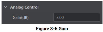
Go to Analog Control, and you can set the device’s gain in Gain(dB) according to actual demands.

8.5.2 Set Brightness
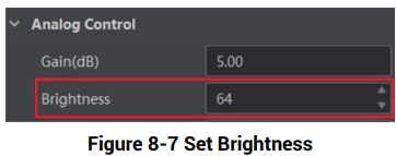
Go to Analog Control, and you can set the device’s brightness according to actual demands. After setting brightness, the device will adjust exposure time automatically to let the image brightness reach the target value.
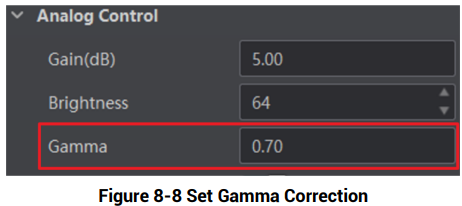
8.5.3 Set Gamma Correction

The device supports Gamma correction function. Generally, the output of the device’s sensor is linear with the photons that are illuminated on the photosensitive surface of the sensor, and Gamma correction provides a non-linear mapping mechanism. Go to Analog Control, and you can set the device’s Gamma according to actual demands
● Gamma value between 0.5 and 1: image brightness increases, dark area becomes brighter.
● Gamma value between 1 and 4: image brightness decreases, dark area becomes darker.
8.5.4 Set White Balance

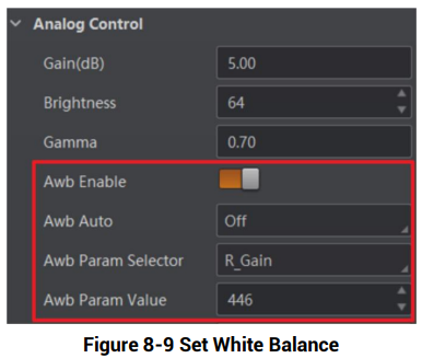
The white balance refers to the device color adjustment depending on different light sources. Adjust the R/G/B ratio to ensure that the white regions are white under different color temperatures. Ideally, the proportion of R/G/B in the white region is 1:1:1.
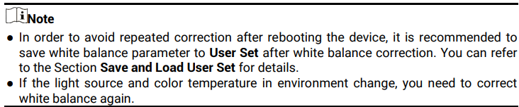
It is recommended to correct white balance when there is great difference between the device’s color effect and actual effect. You can correct white balance as shown below.
Steps
1. Put a white paper in the range of the device’s field of view, and make sure the paper covers the entire field of view.
2. Set exposure and gain.

3. Enable Awb Enable in Analog Control.
4. Set Awb Auto to Continuous.

If there is still great difference between correction effect and actual color, it is recommended to correct white balance according to following steps.
5. Set Awb Auto to Off, and find 1024 in one of R/G/B channel.
6. Manually adjust other two channels by setting Awb Param Selector and Awb Param Value to let these three channels have same value.
8.5.5 Set Color Correction Matrix

After the image is processed by the white balance, the overall image will be dark, and at the same time, various colors may deviate from their standard values to varying degrees.
At this time, it is necessary to multiply the color of the image by the correction matrix to correct each color to its standard value, so that the overall color of the image is more vivid.
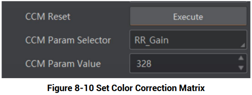
The color correction function is implemented by multiplying each RGB component by a correction matrix.
Steps
1. Click Execute in CCM Reset.
2. Set CCM Param Selector.

3. Set value in CCM Param Value.
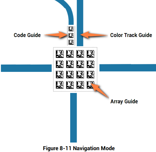
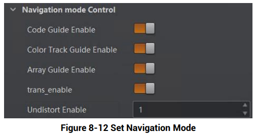
● Code Guide Enable: After enabling it, the device guides the AGV to operate by recognizing code tape on the ground.
● Color Track Guide Enable: After enabling it, the device guides the AGV to operate by recognizing color track on the ground.
● Array Guide Enable: After enabling it, the device guides the AGV to align the center position of matrix code.
● Trans_enable: After enabling it, the device supports outputting AGV’s physical coordinate.
● Undistort Enable: After enabling it, the device supports correcting distortion code.
8.6.2 Set Calibration Parameters
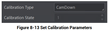
The device supports setting calibration data type and viewing calibration state.
● Calibration Type: It selects different calibration position data.
○ CamDown: It is calibration position data by AGV bottom device.
○ CamUpBefore: It is calibration position data by AGV upper device before lifting.
○ CamUpAfter: It is calibration position data by AGV upper device after lifting.
○ Reserve Type: It is a reserved parameter value.
● Calibration State: You can view calibration state.
8.7 Code Tape Control
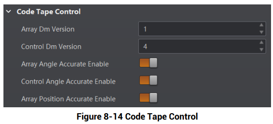
The code type control is used to set DM code type under code guide or array guide navigation mode.
● Array DM Version: It sets DM code type under array guide navigation mode.
● Control DM Version: It sets DM code type under code guide navigation mode.
● Array Angle Accurate Enable: After it is enabled, the angle information of array guide will be calculated via multi-code fitting method for improving angle position accuracy.
● Control Angle Accurate Enable: After it is enabled, the angle information of code guide will be calculated via multi-code fitting method for improving angle position accuracy.
● Array Position Accurate Enable: After it is enabled, the position information of array guide will be calculated via multi-code fitting method for improving position accuracy.
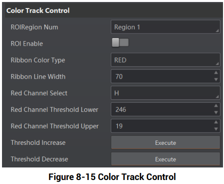
8.8 Color Track Control
The color track control is used to set parameters under color track guide navigation mode.

● ROI Enable: After it is enabled, you can draw the ROI of color track. The related parameters are shown below.
○ ROIRegion Num: It shows the ROI.
○ ROI Width: It is the width of the ROI.
○ ROI Height: It is the height of the ROI.
○ Offset X: It refers to the x-coordinate of the point in the upper-left corner of the ROI.
○ Offset Y: It refers to the y-coordinate of the point in the upper-left corner of the ROI.
● Ribbon Color Type: It selects ribbon color (RED/BLUE/YELLOW/GREEN).
● Ribbon Line Width: It sets ribbon line width ranging from 0 to 270.
● Red/Blue/Yellow/Green Channel Select: It sets H/S/V channel for different colors.
● Red/Blue/Yellow/Green Channel Threshold Lower: It sets lower threshold for selected channels.
● Red/Blue/Yellow/Green Channel Threshold Upper: It sets upper threshold for selected channels.
● Threshold Increase: Click Execute to increase recognition threshold of the color track.
● Threshold Decrease: Click Execute to decrease recognition threshold of the color track.
8.9 Algorithm Parameter Control
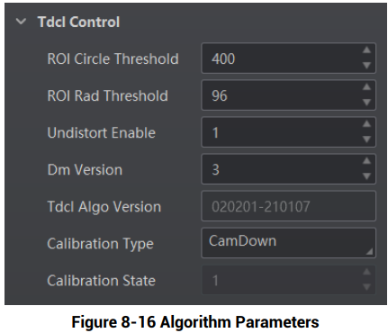
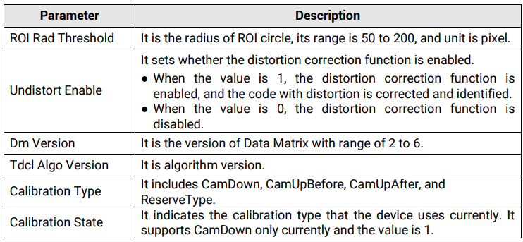
Go to Tdcl Control, you can set the device’s algorithm parameters according to actual demands.

8.10 Light Source Control
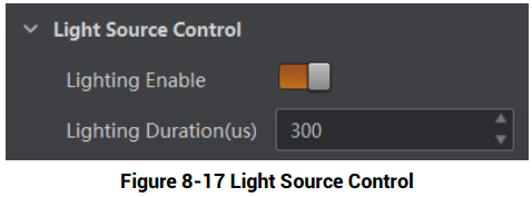
Go to Light Source Control, you can enable Lighting Enable to enable light source. If Lighting Enable is enabled, you can also set Lighting Duration to configure duration.
8.11 Transport Layer Control
8.11.1 Communication Protocol
The device supports different communication protocols, and you can set corresponding parameters after selecting specific protocols.
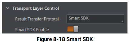
Smart SDK
It is recommended to select Smart SDK if you use SDK to carry out secondary development and receive results.
Steps
1. Go to Transport Layer Control → Result Transfer Protocol.
2. Select Smart SDK as Result Transfer Protocol.
3. Enable Smart SDK.
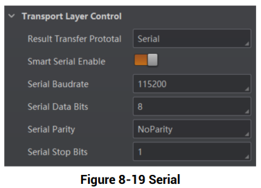
Serial
Steps
1. Go to Transport Layer Control → Result Transfer Protocol.
2. Select Serial as Result Transfer Protocol.
3. Enable Smart Serial Enable.
4. Set Serial Baudrate, Serial Data Bits, Serial Parity, and Serial Stop Bits according to
actual demands.
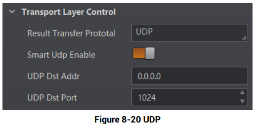
UDP
UDP stands for User Datagram Protocol and is a simple datagram-oriented transport layer protocol.
Steps
1. Go to Transport Layer Control → Result Transfer Protocol.
2. Select UDP as Result Transfer Protocol.
3. Enable Smart UDP Enable.
4. Set UDP Dst Addr and UDP Dst Port according to actual demands.
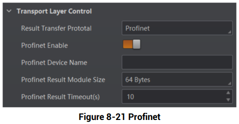
Profinet
Steps
1. Go to Transport Layer Control → Result Transfer Protocol.
2. Select Profinet as Result Transfer Protocol.
3. Enable Profinet Enable.
4. Enter Profinet Device Name, and set Profinet Result Module Size and Profinet Result Timeout according to actual demands.
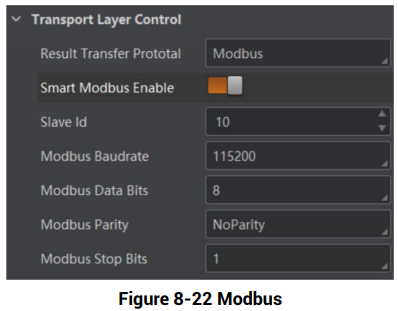
Modbus
Steps
1. Go to Transport Layer Control → Result Transfer Protocol.
2. Select Modbus as Result Transfer Protocol.
3. Enable Smart Modbus Enable.
4. Set Slave ID, Modbus Baudrate, Modbus Data Bits, Modbus Parity, and Modbus Stop Bits.
EthernetIP
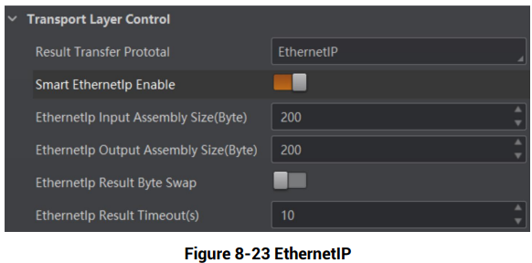
Steps
1. Go to Transport Layer Control → Result Transfer Protocol.
2. Select EthernetIP as Result Transfer Protocol.
3. Enable Smart EthernetIP Enable.
4. Set EthernetIP Input Assembly Size(Byte), Ethernetlp Output Assembly Size(Byte), and Ethernetlp Result Timeout(s), and enable Ethernetlp Result Byte Swap according to actual demands.
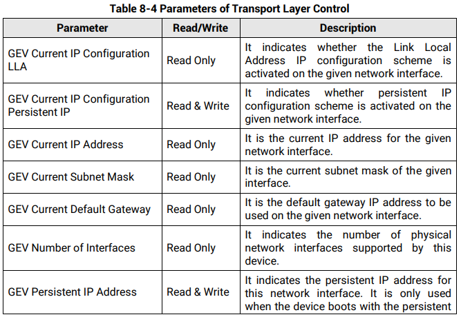
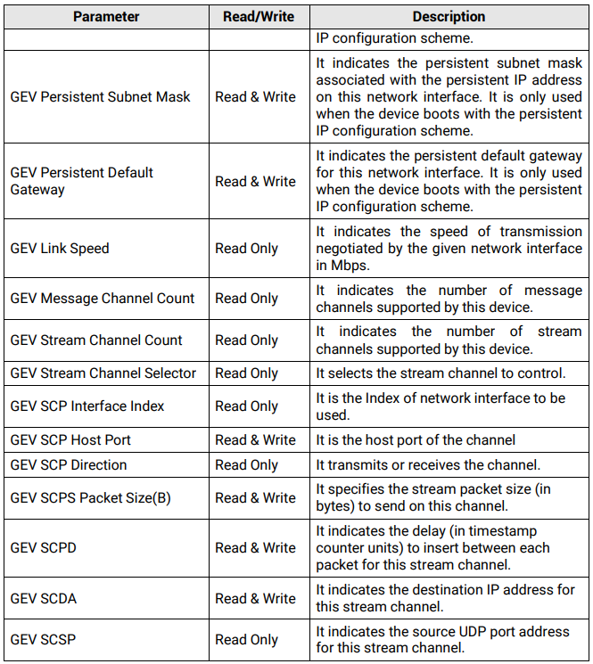
8.11.2 Parameters of Transport Layer Control
You can also go to Transport Layer Control to view the device’s related parameters.
8.12 User Set Customization
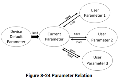
This function allows you to save or load device settings. The device supports four sets of parameters, including one default set and three user sets, and the relation among four sets of parameters is shown below.

8.12.1 Save User Set
Steps
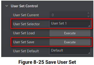
1. Go to User Set Control, and select a user set in User Set Selector.

2. Click Execute in User Set Save to save parameter.
8.12.2 Load User Set

Steps
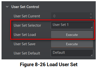
1. Go to User Set Control, and select a user set in User Set Selector.

2. Click Execute in User Set Load to load parameter.
8.12.3 Set User Default
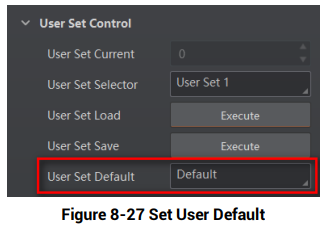
You can also set default parameter by going to User Set Control, and select a user set in User Set Default.

No comments to display
No comments to display