
3. Mechanical and Electric Installation
3.1 Mechanical Installation
3.1.1 Installation environment
1) Ambient temperature: The ambient temperature exerts great influences on the service life of the inverter and is not allowed to exceed the allowable temperature range (-10℃ to 50℃).
2) The inverter should be mounted on the surface of incombustible articles, with sufficient spaces nearby for heat sinking. The inverter is easy to generate large amount of heat during the operation. The inverter should be mounted vertically on the base with screws.
3) The inverter should be mounted in the place without vibration or with vibration of less than 0.6G, and should be kept away from such equipment as punching machine.
4) The inverter should be mounted in locations free from direct sunlight, high humidity and condensate.
5) The inverter should be mounted in locations free from corrosive gas, explosive gas or combustible gas.
6) The inverter should be mounted in locations free from oil dirt, dust, and metal powder.
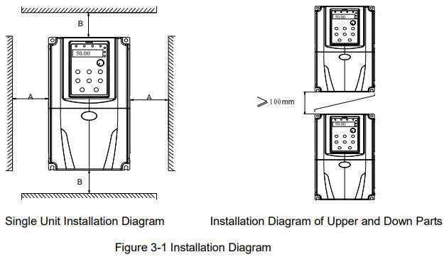
Single Unit Installation: When the inverter power is not higher than 22kW, the A size can be omitted. When the inverter power is higher than 22kW, the A size should be higher than 50mm.
Installation of Upper and Lower Parts: When installing the upper and lower parts of the inverter, the insulating splitter is required.
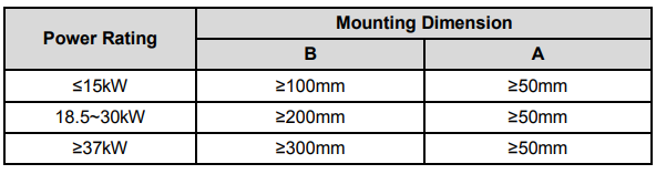
3.1.2 Heat dissipation should be taken into account during the mechanical installation. Please pay attention the following items:
1) Install the inverter vertically so that the heat may be expelled from the top. However, the equipment cannot be installed upside down. If there are multiple inverters, parallel installation is a better choice. In applications where the upper and lower inverters need to be installed, please refer to Figure 3-1 “KE300 Series Inverter Installation Diagram” and install an insulating splitter.
2) The mounting space should be as indicated as Figure 3-1, so as to ensure the heat dissipation space of the inverter. However, the heat dissipation of other devices in the cabinet should also be taken into account.
3) The installation bracket must be flame retardant.
4) In the applications where there are metal dusts, it is recommended to mount the radiator outside the cabinet. In this case, the space in the sealed cabinet should be large enough.
3.2 Electrical Installation
3.2.1 Guide to the external electrical parts
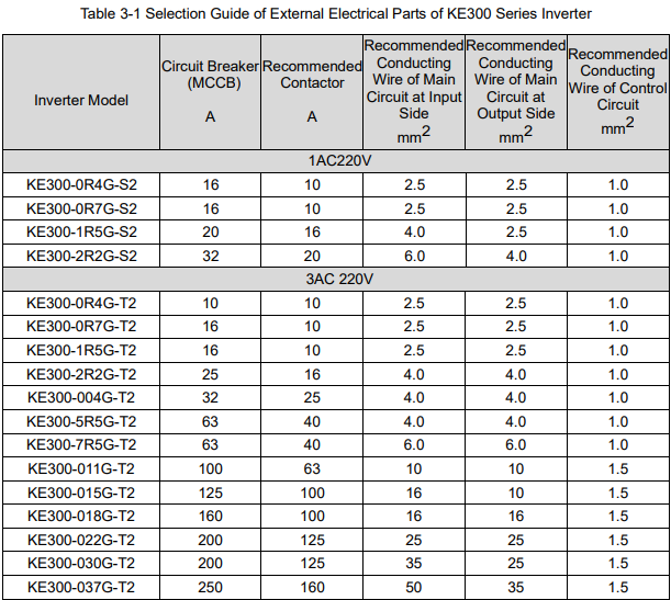
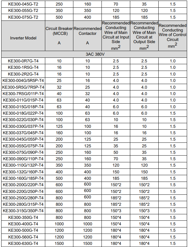
3.2.2 Connection to peripheral devices
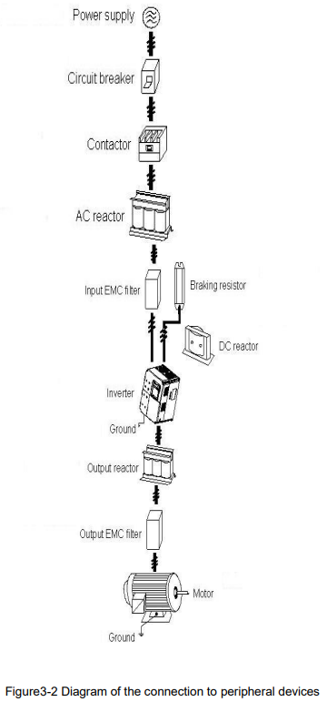
Do not install the capacitor or surge suppressor at the output side of the inverter, otherwise it may cause inverter failure or capacitor and surge suppressor damaged.
The Inverter input / output (main circuit) contains harmonic components, it may interfere with inverter accessories communications equipment. Therefore, please install anti-interference filter to minimize interference.
The details of external devices and accessories selection refer to the manual of external devices.
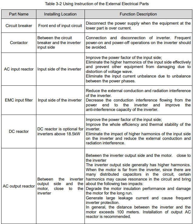
3.2.3 Using instruction of the external electrical parts
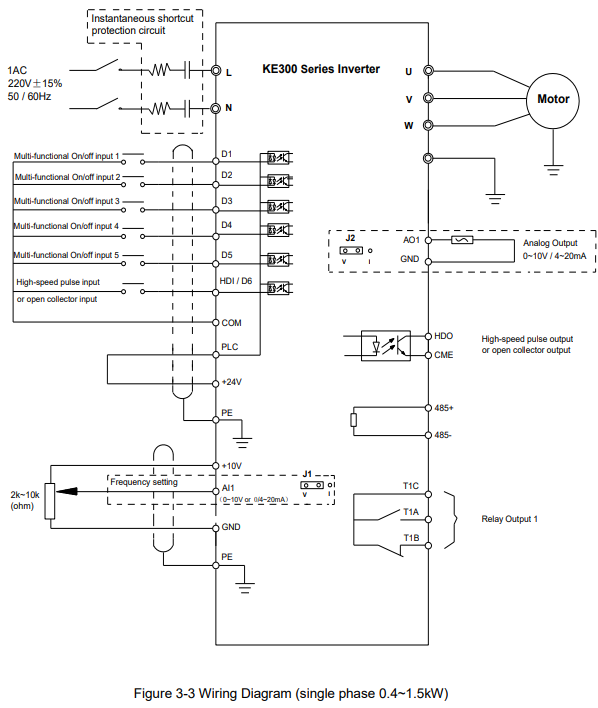
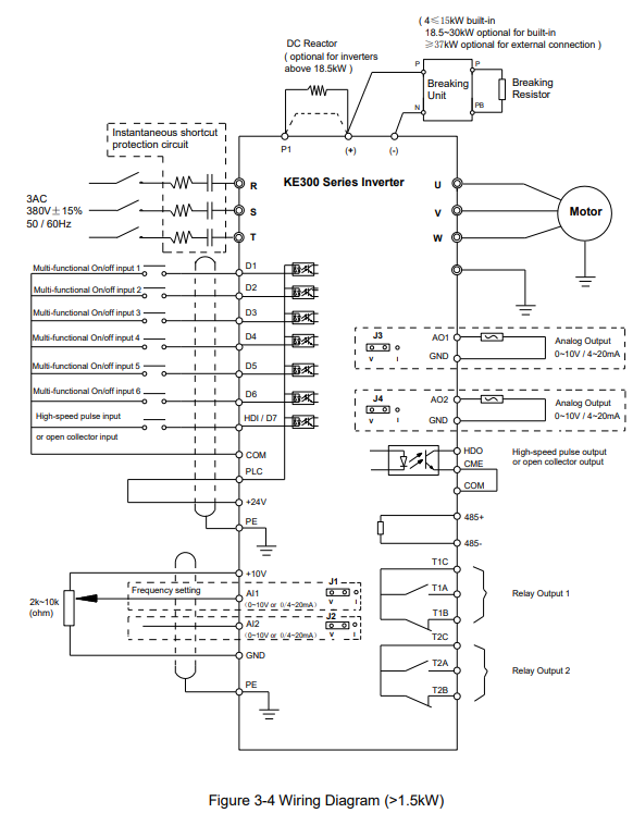
3.2.4 Wiring diagram
Note:
1. Terminal ◎ refers to the main circuit terminal, terminal ○ refers to the control circuit terminal.
2. Built-in braking unit is standard in the inverters below 18.5kW, and optional for 18.5 ~ 30kW inverters.
3. Braking resistor is optional for user.
3.2.5 Main circuit terminals and connections
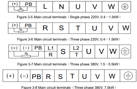
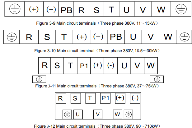
1) Main circuit terminals
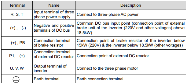
2) Instructions of main circuit terminals
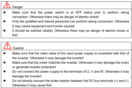
Precautions on Wiring:
a) Input power R, S and T:
There is no phase sequence requirement for the cable connection at the input side of the inverter,
b) DC bus (+) and (-) terminals:
Note that the (+) and (-) terminals of DC bus have residual voltage right after power-on. It needs to wait until the CHARGE indictor is OFF and make sure that the voltage is less than 36V prior to wiring
connection. Otherwise there may be danger of electric shock.
When selecting external brake unit for the inverter above 18.5kW, the poles of (+) and (-) should not be connected reversely, or it may damage the inverter and even cause fire.
The wiring length of the brake unit should not exceed 10 meters. Twisted wires or pair wires should be used and connected in parallel.
Do not connect the brake resistor directly to the DC bus, or it may damage the inverter and even cause fire.
c) Connecting terminals (+) and PB of brake resistor:
The connecting terminals of the brake resistor are effective only for the inverter of less than 30kW with built-in brake unit.
The prototype of brake resistor can refer to the recommended value and the wiring length should be less than 5 meters. Otherwise it may damage the inverter.
d) Connecting terminals P1 and (+) of external DC reactor:
For the inverter above 18.5kW with external reactor, when assembling, remove the connector between terminals P1 and (+), and connect a DC reactor instead.
e) Terminals U, V, W at the output side of the inverter:
The inverter output side cannot connect to the capacitor or surge absorber. Otherwise, it may cause frequent inverter protection and even damage the inverter.
In case the motor cable is too long, it may generate electrical resonance easily due to the impact of distributed capacitance, thus damaging the motor insulation or generating higher leakage current to invoke over current protection of the inverter. When the length of motor cable is longer than 100 meters, it needs to install a AC output reactor.
f) Earth terminal PE :
This terminal should be earthed reliably, with resistance of earth cable of less than 0.1Ω. Otherwise, it may cause fault or damage the inverter.
Do not share the earth terminal and zero line of the power supply.
3.2.6 Control terminals and connections
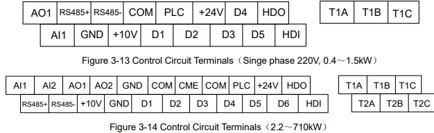
1) Control circuit terminals
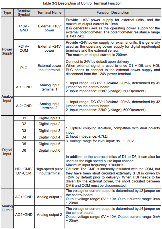
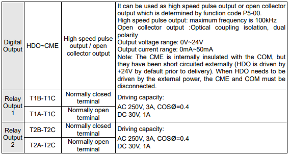
2) Function description of control terminal
3) Description of connection of control terminals
a) Analog input terminal
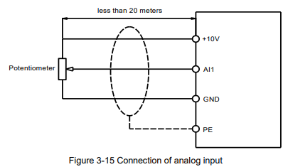
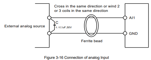
Since the weak analog voltage signal is easy to suffer external interferences, it needs to employ shielded cable generally and the length should be no longer than 20 meters, as shown in Figure 3-5. In case the analog signal is subject to severe interference, and filter capacitor or ferrite magnetic core should be installed at analog signal source side, as shown in Figure 3-6.
b) Digital input terminal
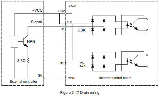
It needs to employ shielded cable generally, with cable length of no more than 20 meters. When active driving is adopted, necessary filtering measures should be taken to prevent the interference to the power supply.
It is recommended to use the contact control mode.
D1~D7 terminal connection: Drain wiring
No comments to display
No comments to display