
4. Operation and Display
4.1 Keypad Description
With the operation keypad, it can perform such operations on the inverter as function parameter modification, working status monitor and running control (start and stop).
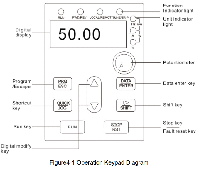
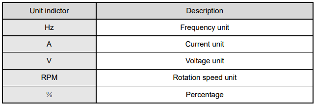
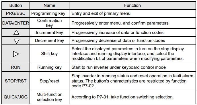
1) Function key description
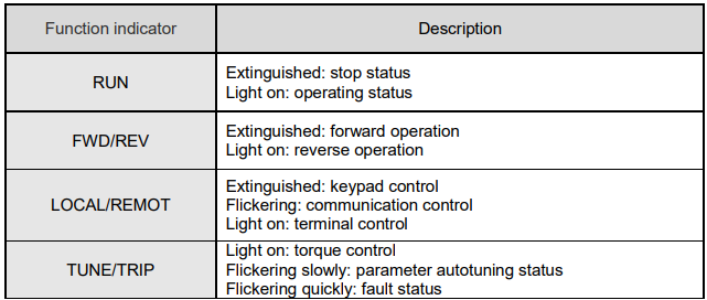
2) Unit indictor light description
3) Digital display zone
Five-number digit LED display, can display setting frequency, output frequency, various monitoring data and alarm code.
4.2 Function Code Checking and Modification Methods Description
The operation keypad of the KE300 Series Inverter adopts three-level menu structure to carry out
operations such as parameter setting.
The three-level menu includes function parameter group (level 1 menu) → Function code (level 2 menu) → Function code setting value (level 3 menu). Refer to Figure 4-2 for the operation procedure.
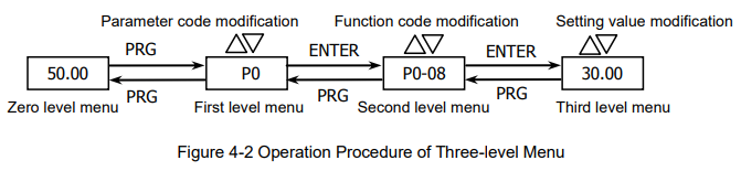
Description: When operating on level 3 menu, press PRG key or ENTER key to return to level 2 menu. The difference between PRG key and ENTER key is described as follows: Pressing ENTER KEY will save the setup parameter and return to the level 2 menu and then automatically shift to the next function code, while pressing PRG key will directly return to level 2 menu without saving the parameter, and it will return to the current function code.
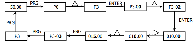
Example: Modify the function code P3-02 from 10.00Hz to 15.00Hz. (The bold-type word indicates the flashing bit.)
4.3 Power-on Initialization
Firstly the system initializes during the inverter power-on, and LED displays “8.8.8.8.8.8”. After initialization, the inverter is in fault protection status if a fault happens, or the inverter is in stand-by status
4.4 Fault Protection
In fault status, inverter will display fault code & record output current, output voltage, etc. For details, please refer to P9 (fault and protection) parameter group. Fault can be reset via STOP/RST key or external terminals.
4.5 Stand By
In stop or stand by status, parameters of multi-status can be displayed. Whether or not to display this parameter can be chosen through function code P7-05 (Stop status display parameter) according to binary bits.
In stop status, there are thirteen parameters can be chosen to display or not. They are: setting frequency, bus voltage, DI input status, DO output status, analog input AI1 voltage, analog input Al2 voltage, radiator temperature, count value, actual length, PLC running step, load speed display, PID setting, HDI input pulse frequency. The displaying of the chosen parameters can be switched in sequence by press “ ” button.
Power on after power-off, the displayed parameters would be default considered as the chosen parameters before power-off.
4.6 Running
In running status, there are thirty two parameters can be chosen to display or not through function code P7-04 (running status display parameter 2) according to binary bits. They are: running frequency, setting frequency, DC bus voltage, output voltage, output current, output torque, DI input status, DO output status, analog input AI1 voltage, analog input AI2 voltage, radiator temperature, actual count value, actual length, line speed, PID setting, PID feedback, etc. The displaying of the chosen parameters can be switched in sequence by pressing “ ” button.
4.7 Password Setting
The inverter provides user password protection function. When PP-00 is set to non-zero value, it indicates the user password, and the password protection turns valid after exiting the function code editing status.
When pressing PRG key again, “------“ will be displayed, and common menu cannot be entered until user password is input correctly.
To cancel the password protection function, enter with password and set PP-00 to “0”.
4.8 Motor Parameters Autotuning
To select the vector control running mode, it must input the nameplate parameter of the motor accurately prior to the running of the inverter. The Inverter will select standard motor parameters matching the nameplate parameter. Since the vector control mode relies highly on the motor parameters, it must acquire the accurate parameters of the controlled motor to ensure the good control performance.
The procedures for the automatic tuning of motor parameters are described below:
First, select the command source (P0-02) as the command channel of the operation keypa. Second, input the following parameters in accordance with the actual motor parameters:
P1-01: Rated motor power
P1-02: Rated motor voltage
P1-03: Rated motor current
P1-04: Rated motor frequency
P1-05: Rated rotation speed of motor
If the motor is completely disconnected from the load, set P1.11 to “2” (complete tuning), and press RUN key on the keyboard keypad, then the inverter will automatically calculate the following parameters:
P1-06: Stator resistance
P1-07: Rotor resistance
P1-08: Leakage inductance
P1-09: Mutual inductance
P1-10: Current without load
Finally, complete the automatic tuning of motor parameters.
If the motor cannot be completely disconnected with the load, set P1-11 to “1” (static tuning), and then press RUN key on the keyboard panel.
The following motor parameters can be calculated automatically:
P1-06: Stator resistance
P1-07: Rotor resistance
P1-08: Leakage inductive reactance
No comments to display
No comments to display