
9. MODBUS Communication Protocol
KE300 series inverter provides RS485 communication interface, and adopts MODBUS communication protocol. User can realize centralized monitoring through PC/PLC, host computer, and also can set inverter’s operating commands, modify or read function parameters, read operating status and fault information, etc.
9.1 About Protocol
This serial communication protocol defines the transmission information and use format in the series communication. It includes the formats of master-polling, broadcast and slave response frame, and master coding method with the content including slave address (or broadcast address), command, transmiting data and error checking. The response of slave adopts the same structure, including action confirmation, returning the data and error checking etc. If slave takes place the error while it is receiving the information or cannot finish the action demanded by master, it will send one fault signal to master as a response.
9.2 Application Method
The inverter could be connected into a “Single-master Multi-slave” PC/PLC control network with RS485 bus.
9.3 Bus Structure
(1) Interface mode
RS485
(2) Transmission mode
There provide asynchronous series and half-duplex transmission mode. At the same time, just one can send the data and the other only receives the data between master and slave. In the series asynchronous communication, the data is sent out frame by frame in the form of message.
(3) Topological structure
In Single-master Multi-slave system, the setup range of slave address is 0 to 247. 0 refers to broadcast communication address. The address of slave must be exclusive in the network. That is basic condition of MODBUS communication.
9.4 Protocol Description
KE300 series inverter communication protocol is a kind of asynchronous serial master-slave communication protocol. In the network, only one equipment (master) can build a protocol (Named as “Inquiry/Command”). Other equipments (slave) response “Inquiry/Command” of master only by providing the data, or doing the action according to the master’s “Inquiry/Command”. Here, master is Personnel Computer, Industrial control equipments or Programmable logical controller, and the slave is inverter or other communication equipments with the same communication protocol. Master not only can visit some slave separately for communication, but also sends the broadcast information to all the slaves. For the single “Inquiry/Command” of master, all of slaves will return a signal that is a response; for the broadcast information provided by master, slave needs not feedback a response to master.
9.5 Communication Data Structure
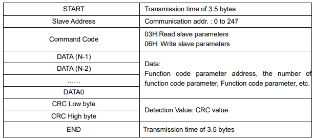
MODBUS protocol communication data format of KE300 series inverter is shown as following:
In RTU mode, the Modbus minimum idle time between frames should be no less than 3.5 bytes. The checksum adopts CRC-16 method. All data except checksum itself sent will be counted into the calculation. Please refer to section: CRC Check for more information. Note that at least 3.5 bytes of Modbus idle time should be kept and the start and end idle time need not be summed up to it.
The entire message frame must be transmitted as a continuous data stream. If a idle time is more than 1.5 bytes before completion of the frame, the receiving device flushes the incomplete message and assumes that the next byte will be the address field of a new message. Similarly, if a new message begins earlier than 3.5 bytes interval following a previous message, the receiving device will consider it as a continuation of the previous message. Because of the frame’s confusion, at last the CRC value is incorrect and communication fault will occur.
RTU frame format:
9.6 Command Code and Communication Data Description
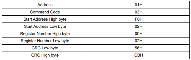
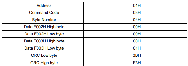
9.6.1 Command code: 03H, reads N words. (There are 12 characters can be read at the most.)
For example: The inverter start address F002 of the slave 01 continuously reads two consecutive values.
Master command information
Slave responding information
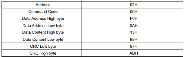
9.6.2 Command code: 06H, write a word
For example: Write 5000(1388H) into address F00AH, slave address 02H.
Master command information
9.6.3 CRC checking
In RTU mode, messages include an error-checking field that is based on a CRC method. The CRC field checks the contents of the entire message. The CRC field is two bytes, containing a 16-bit binary value.
The CRC value is calculated by the transmitting device, which appends the CRC to the message. The receiving device recalculates a CRC during receipt of the message, and compares the calculated value to the actual value received in the CRC field. If the two values are not equal, an error results.
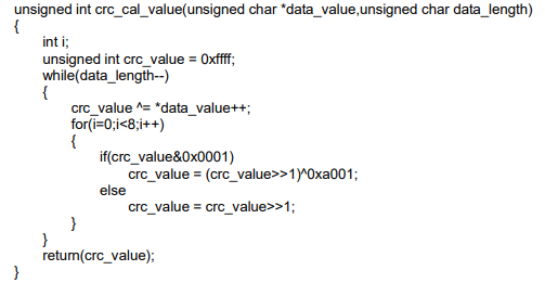
The CRC is started by 0xFFFF. Then a process begins of applying successive eight-bit bytes of the message to the current contents of the register. Only the eight bits of data in each character are used for generating the CRC. Start and stop bits, and the parity bit, do not apply to the CRC.
During generation of the CRC, each eight-bit character is exclusive ORed with the register contents. Then the result is shifted in the direction of the least significant bit (LSB), with a zero filled into the most significant bit (MSB) position. The LSB is extracted and examined. If the LSB was a 1, the register is then exclusive ORed with a preset, fixed value. If the LSB was a 0, no exclusive OR takes place. This process is repeated until eight shifts have been performed. After the last (eighth) shift, the next eight-bit byte is exclusive ORed with the register's current value, and the process repeats for eight more shifts as described above. The final contents of the register, after all the bytes of the message have been applied, is the CRC value.
When the CRC is appended to the message, the low byte is appended first, followed by the high byte. The following are C language source code for CRC-16.
9.6.4 Address definition of communication parameter
Here is about address definition of communication parameter. It’s used to control the inverter operation, status and related parameter setting.
(1) The mark rules of function code parameters address:
The group number and mark of function code is the parameter address for indicating the rules.
P0~PF group parameter address:
High byte: F0 to FF, low byte: 00 to FF
A0 group parameter address:
High byte: A0, low byte: 00 to FF
U0 group parameter address:
High byte: 70H, low byte: 00 to FF
For example: P3-12, address indicates to F30C
PC-05, address indicates to FC05
A0-01, address indicates to A001
U0-03, address indicates to 7003
Note:
1. Group PF: Either the parameter cannot be read, nor be changed.
2. Group U0: Only for reading parameter, cannot be changed parameters.
3. Some parameters cannot be changed during operation; some parameters regardless of what kind of status the inverter in, the parameters cannot be changed. Change the function code parameters, pay attention to the scope of the parameters, units, and relative instructions.
Besides, due to EEPROM be frequently stored, it will reduce the lifetime of EEPROM. So in the communication mode, some function code needn’t be stored, only change the RAM value. To achieve this function, change high order P of the function code into zero.
Corresponding function code addresses are indicated below:
P0~PF group parameter address:
High byte: 00 to FF, low byte: 00 to FF
A0 group parameter address:
High byte: 40, low byte: 00 to FF
U0 group parameter address:
High byte: 70H, low byte: 00 to FF
For example:
P3-12, address indicates to 030C
PC-05, address indicates to 0C05
A0-01, address indicates to 4001
These addresses can only act writing RAM, it cannot act reading. When act reading, it is invalid address.
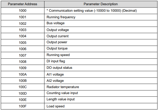
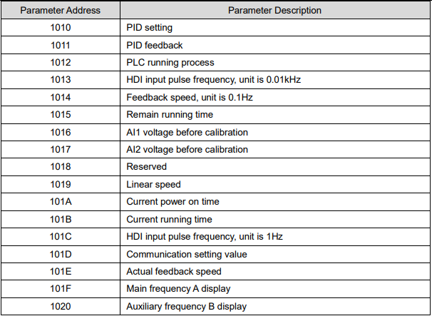
(2) Stop/start parameter address
Note:
Communication setting value is the percentage of relative value, and 10,000 corresponds to 100.00%,
-10000 corresponds to -100.00%.
To the data of frequency, the percentage is the percentage of relative maximum frequency (P0-10).
To the data of torque, the percentage is P2-10 (torque upper limit).
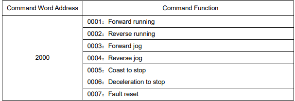
(3) Control command input to inverter (write only)
(4) Read inverter status: (read only)

(5) Parameters locking password check: (If the return is 8888H, it means the password check passes.)

(6) Digital output terminal control: (write only)
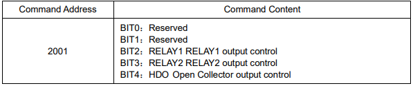
(7) Analog output AO1 control: (write only)

(8) Analog output AO2 control: (write only)

(9) Pulse output control: (write only)

(10) Inverter fault code description:

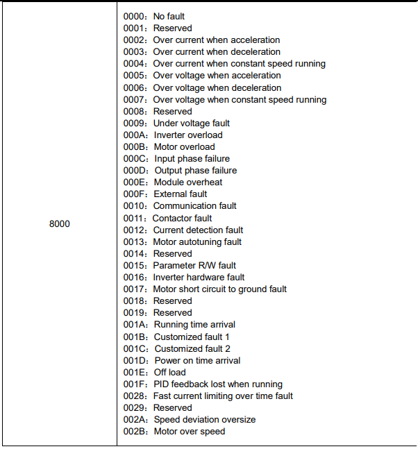
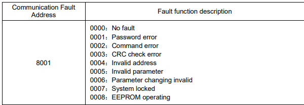
9.6.5 Description data of communication fault information (fault code)
9.7 PD Group Communication Parameter Description
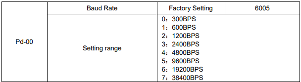
This parameter is used to set the data transmission rate between host computer and the inverter. Please note that baud rate of the host computer and inverter must be the same. Otherwise, the communication is impossible. The bigger baud rate is, the faster communication is.

The setting data format of host computer and inverter must be the same; otherwise, the communication is impossible.

When the local address is set to be 0, that is broadcast address, it can realize the broadcast function of host computer.
Local address must be unique (except broadcast address). This is the base of point-to-point communication between host computer and inverter.

Response delay: It refers to the interval time from the inverter finishes receiving data to sending data to the host computer. If the response delay is less than system processing time, then the response delay is based on the system processing time. If the response delay is more than system processing time, after the system processing the data, it should be delayed to wait until the response delay time arrives, then sending data to host computer.

When the function code set to be 0.0 s, the communication timeout parameter is invalid.
When the function code set to be valid value, if the interval time between the communication and the next communication is beyond the communication timeout, the system will report communication failure error (Err16). At normal circumstances, it is set to be invalid. If in the continuous communication system, set the parameter, you can monitor the communication status.

PD-05=1: Select standard MODBUS protocol
PD-05=0: When reading the command, the slave return is one byte than the standard MODBUS protocol’s, for details refer to communications Data Structure of this protocol.

It is used to confirm the output current unit when communication reads output current.
No comments to display
No comments to display