
2. HARDWARE OVERVIEW
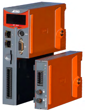
Motion Coordinator MC464
OVERVIEW
The Motion Coordinator MC464 is Trio’s new generation modular servo control positioner with the ability to control servo or stepper motors by means of Digital Drive links (e.g. EtherCAT, Sercos, etc) or via traditional analogue and encoder or pulse and direction. A maximum of 7 expansion modules can be fitted to control up to 64 axes which gives the flexibility required in modern system design. The MC464 is housed in a rugged plastic case with integrated earth chassis and incorporates all the isolation circuitry necessary for direct connection to external equipment in an industrial environment. Filtered power supplies are included so that it can be powered from the 24V d.c. logic supply present in most industrial cabinets.
It is designed to be configured and programmed for the application using a PC running the Motion Perfect application software, and then may be set to run “standalone” if an external computer is not required for the final system.
The Multi-tasking version of TrioBASIC for the MC464 allows up to 22 TrioBASIC programs to be run simultaneously on the controller using pre-emptive multi-tasking. In addition, the operating system software includes the IEC 61131-3 standard run-time environment (licence key required).
PROGRAMMING
The Multi-tasking ability of the MC464 allows parts of a complex application to be developed, tested and run independently, although the tasks can share data and motion control hardware. IEC 61131-3 programs can be run at the same time as TrioBASIC allowing the programmer to select the best features of each.
I/O CAPABILITY
The MC464 has 8 built in 24V inputs and 8 bi-directional I/O channels. These may be used for system interaction or may be defined to be used by the controller for end of travel limits, registration, datuming and feedhold functions if required. Each of the Input/Output channels has a status indicator to make it easy to check them at a glance. The MC464 can have up 512 external Input/Output channels connected using DIN rail mounted CAN I/O modules. These units connect to the built-in CAN channel.
COMMUNICATIONS
A 10/100 base-T Ethernet port is fitted as standard and this is the primary communications connection to the MC464. Many protocols are supported including Telnet, Modbus TCP, Ethernet IP and TrioPCMotion. Check the Trio website (www.triomotion.com) for a complete list.
The MC464 has one built in RS232 port and one built in duplex RS485 channel for simple factory communication systems. Either the RS232 port or the RS485 port may be configured to run the Modbus or Hostlink protocol for PLC or HMI interfacing.
If the built-in CAN channel is not used for connecting I/O modules, it may optionally be used for CAN communications. E.g. DeviceNet slave or CANopen master.
The Anybus CompactCom Carrier Module (P875) can be used to add other fieldbus communications options
REMOVABLE STORAGE
The MC464 has a SD Card slot which allows a simple means of transferring programs, firmware and data without a PC connection. Offering the OEM easy machine replication and servicing.
The memory slot is compatable with a wide range of SD cards up to 2Gbytes using the FAT32 compatible file system.

AXIS POSITIONING FUNCTIONS
The motion control generation software receives instructions to move an axis or axes from the TrioBASIC or IEC 61131-3 language which is running concurrently on the same processor. The motion generation software provides control during operation to ensure smooth, coordinated movements with the velocity profiled as specified by the controlling program. Linear interpolation may be performed on groups of axes, and circular, helical or spherical interpolation in any two/three orthogonal axes. Each axis may run independently or they may be linked in any combination using interpolation, CAM profile or the electronic gearbox facilities.
Consecutive movements may be merged to produce continuous path motion and the user may program the motion using programmable units of measurement (e.g. mm, inches, revs etc.). The module may also be programmed to control only the axis speed. The positioner checks the status of end of travel limit switches which can be used to cancel moves in progress and alter program execution.
CONNECTIONS TO THE MC464
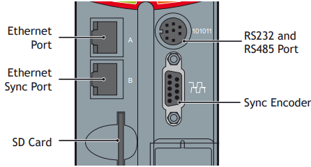
ETHERNET PORT CONNECTION
Physical layer: 10/100 base_T
Connector: RJ45
The Ethernet port is the default connection between the Motion Coordinator and the host PC running Motion Perfect programming.

ETHERNET SYNC PORT
Not used.
MC464 SERIAL CONNECTIONS
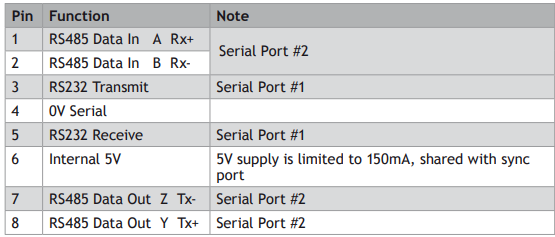
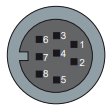
The MC464 features two serial ports. Both ports are accessed through a single 8 pin connector.
SERIAL CONNECTOR
SYNC ENCODER
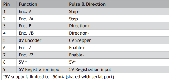
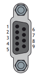
The sync encoder port is bidirectional. It can be used as a reference encoder input or as an encoder simulation output to act as a master reference for other parts of the system
REGISTRATION
The MC464 built in port has 2 available registration events. These can be used with the Z mark, the registration input on the sync port, input 0 or input 1.
24V POWER SUPPLY INPUT
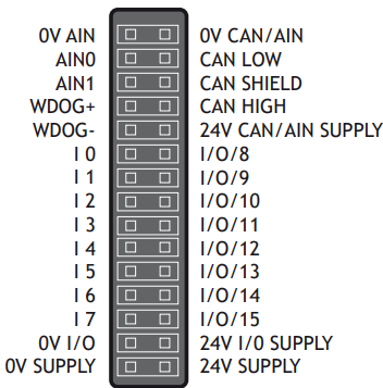
The MC464 is powered entirely via the 24V d.c.supply connections. The unit uses internal DC-DC converters to generate independent 5V logic supply, the encoder/serial 5V supply and other internal power supplies. I/O, analogue and CANbus circuits are isolated from the main 24V power input and must be powered separately. For example; it is often necessary to power the CANbus network remotely via the CANbus cable.
24V d.c., Class 2 transformer or power source required for UL compliance. The MC464 is grounded via the metal chassis. It MUST be installed on an unpainted metal plate or DIN rail which is connected to earth.
AMPLIFIER ENABLE (WATCHDOG) RELAY OUTPUTS
One internal relay contact is available to enable external amplifiers when the controller has powered up correctly and the system and application software is ready. The amplifier enable is a solid-state relay with an ON resistance of 25 ohms at 100mA. The enable relay will be open circuit if there is no power on the controller OR a motion error exists on a servo axis OR the user program sets it open with the WDOG=OFF command.
The amplifier enable relay may, for example, be incorporated within a hold-up circuit or chain that must be intact before a 3-phase power input is made live.
ALL STEPPER AND SERVO AMPLIFIERS MUST BE INHIBITED WHEN THE AMPLIFIER ENABLE OUTPUT IS OPEN CIRCUIT
CANBUS
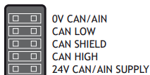
The MC464 features a built-in CAN channel. This is primarily intended for Input/Output expansion via Trio’s range of CAN digital and analogue I/O modules. It may be used for other purposes when I/O expansion is not required.
The CANbus port is electrically equivalent to a DeviceNet node.
ANALOGUE INPUTS
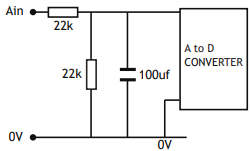
Two built-in 12 bit analogue inputs are provided which are set up with a scale of 0 to 10V. External connection to these inputs is via the 2-part terminal strip on the lower front panel.
A 24V d.c. supply must be applied to the CANbus port to provide power for the analogue input circuit.
24V INPUT CHANNELS
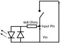
The Motion Coordinator has 16 24V Input channels built into the master unit. These may be expanded to 256 Inputs by the addition of CAN-16 I/O modules.
All of the 24V Input channels have the same circuit although 8 on the master unit have 24V Output channels connected to the same pin. These bidirectional channels may be used for Input or Output to suit the application. If the channel is to be used as an Input then the Output should not be switched on in the program.
24V I/O CHANNELS
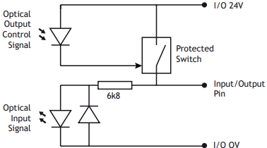
Input/output channels 8..15 are bi-directional and may be used for Input or Output to suit the application. The inputs have a protected 24V sourcing output connected to the same pin. If the channel is to be used as an Input then the Output should not be switched on in the program. The input circuitry is the same as on the dedicated inputs. The output circuit has electronic over-current protection and thermal protection which shuts the output down when the current exceeds 250mA.
Care should be taken to ensure that the 250mA limit for the output circuit is not exceeded, and that the total load for the group of 8 outputs does not exceed 1A
BATTERY
The MC464 incorporates a user replaceable battery for the battery back-up RAM. For replacement, use battery model CR2450 or equivalent.
To replace the battery, insert screwdriver under the frontmost ventilation slot (A) and prize off the battery cover (B) and pull the battery ribbon to lift the battery (C) from the MC464. Replacing is the reverse of the procedure.
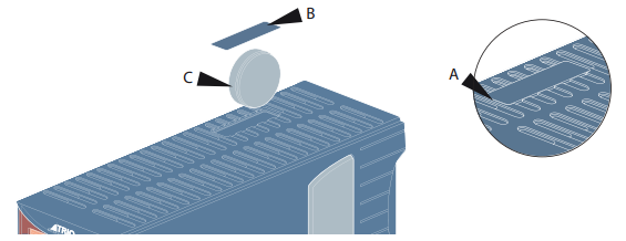
TO AVOID LOSING THE MEMORY CONTENTS, THE NEW BATTERY SHOULD BE INSERTED WITHIN 30 SECONDS OF THE OLD ONE BEING REMOVED.
BACKLIT DISPLAY
The information display area shows the IP address and subnet mask during power-up and whenever an Ethernet cable is first connected to the MC464. During operation, this display shows run, Off or Err to indicate the MC464 status. Below the main status display are the ERROR, ENABLE and BATTERY LOW indicators.
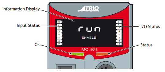
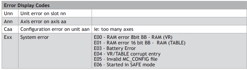
ERROR An error has occurred (see Error Display Codes table below for details).
ENABLE When illuminated, WDOG is ON.
BATTERY LOW When illuminated the battery needs replacing.
A bank of 8 indicators at the left side shows the Digital Input States and a similar bank on the right shows the state of I/O8 to I/O15. The I/O displayed can be altered using the DISPLAY command.
Two LED’s are provided to show the processor (OK) and system status.
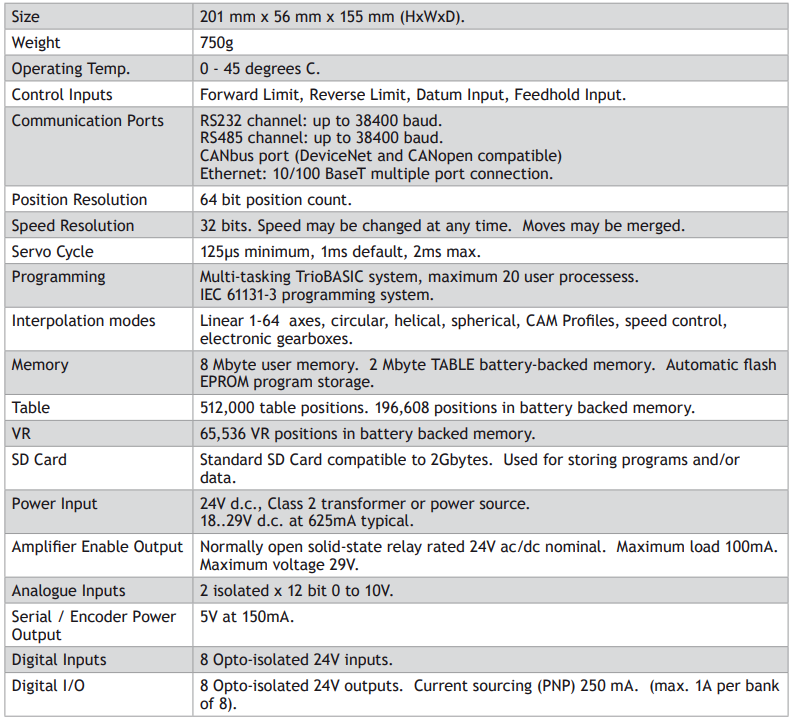
MC464 FEATURE SUMMARY
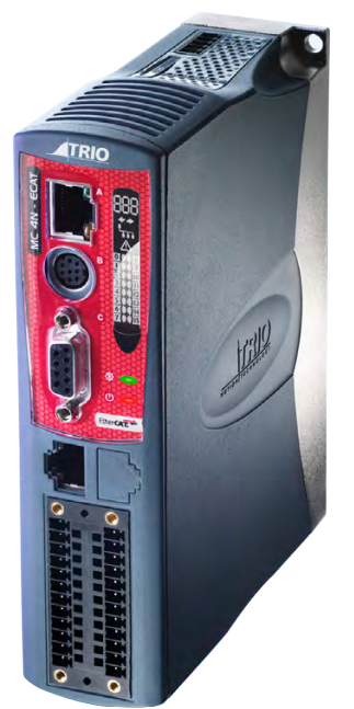
Motion Coordinator MC4N-Mini EtherCAT Maste
OVERVIEW
The MC4N is a new concept in high performance Motion Coordinators which is dedicated to running remote servo and stepper drives via the EtherCAT real time automation bus. It is based on an up-rated version of the 532MHz ARM 11 processor which makes it ideal for high axis count machines or robotic
applications.
It is designed to be configured and programmed for the application using a PC running the Motion Perfect application software, and then may be set to run “standalone” if an external computer is not required for the final system.
The Multi-tasking version of TrioBASIC for the MC4N allows up to 22 TrioBASIC programs to be run simultaneously on the controller using pre-emptive multi-tasking. In addition, the operating system software includes the IEC 61131-3 standard run-time environment (licence key required).
Versions of the MC4N are available for 2, 4, 8, 16 and 32 motor axes. All versions feature 32 software axes any of which may be used as virtual axes if not assigned to EtherCAT hardware.
PROGRAMMING
The Multi-tasking ability of the MC4N allows parts of a complex application to be developed, tested and run independently, although the tasks can share data and motion control hardware. IEC 61131-3 programs can be run at the same time as TrioBASIC allowing the programmer to select the best features of each.
I/O CAPABILITY
The MC4N has 8 built in 24V inputs and 8 bi-directional I/O channels. These may be used for system interaction or may be defined to be used by the controller for end of travel limits, registration, datuming and feedhold functions if required. Each of the Input/Output channels has a status indicator to make it easy to check them at a glance. The MC4N can have up 512 external Input/Output channels connected using DIN rail mounted CAN I/O modules. These units connect to the built-in CAN channel.
COMMUNICATIONS
A 10/100 base-T Ethernet port is fitted as standard and this is the primary communications connection to the MC4N. Many protocols are supported including Telnet, Modbus TCP, Ethernet IP and TrioPCMotion. Check the Trio website (www.triomotion.com) for a complete list.
The MC4N has one built in RS232 port and one built in duplex RS485 channel for simple factory communication systems. Either the RS232 port or the RS485 port may be configured to run the Modbus or Hostlink protocol for PLC or HMI interfacing.
If the built-in CAN channel is not used for connecting I/O modules, it may optionally be used for CAN communications. E.g. DeviceNet slave or CanOpen master.
REMOVABLE STORAGE
The SD Card maybe used for storing or transfering programs, reciepes and data to and from the MC4N. The card must be FAT32 format and a maximum 16Gb size.
SD CARDS MAY BE FAT16 FORMATTED WHEN PURCHASED. RE-FORMAT IN A PC TO FAT32
PRIOR TO USE.

AXIS POSITIONING FUNCTIONS
The motion control generation software receives instructions to move an axis or axes from the TrioBASIC or IEC 61131-3 language which is running concurrently on the same processor. The motion generation software provides control during operation to ensure smooth, coordinated movements with the velocity profiled as specified by the controlling program. Linear interpolation may be performed on groups of axes, and circular, helical or spherical interpolation in any two/three orthogonal axes. Each axis may run independently or they may be linked in any combination using interpolation, CAM profiles or the electronic gearbox facilities.
Consecutive movements may be merged to produce continuous path motion and the user may program the motion using programmable units of measurement (e.g. mm, inches, revs etc.). The module may also be programmed to control only the axis speed. The positioner checks the status of end of travel limit switches which can be used to cancel moves in progress and alter program execution.
CONNECTIONS TO THE MC4N
ETHERNET PORT CONNECTION
Physical layer: 10/100 base_T
Connector: RJ45
A standard Ethernet connector is provided for use as the primary programming interface.
The Trio programming software, Motion Perfect, must be installed on a Windows based PC that is fitted with an Ethernet connection. The IP address is displayed on the MC4N display for a few seconds after power-up or when an Ethernet cable is plugged in.
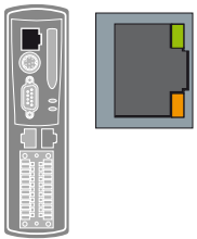
Ethernet cable must be CAT 5 or better.
The Standard Ethernet connection may also be used for Ethernet-IP, Modbus and other factory communications.
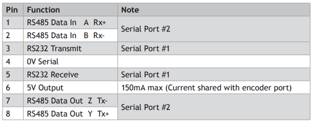
SERIAL CONNECTIONS
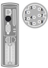
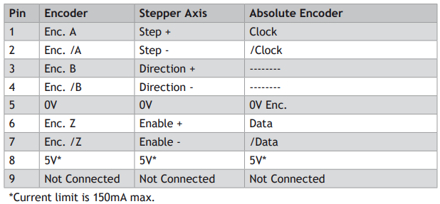
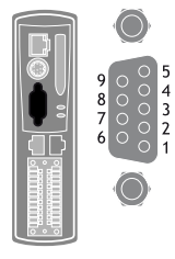
FLEXIBLE AXIS PORT
ETHERCAT PORT
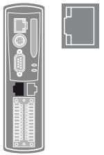
The MC4N acts as an EtherCAT master. EtherCAT drives and I/O devices are normally connected in a chain. Other topologies are possible when specialised EtherCAT routers are used in the network.
Up to 32 EtherCAT axes and 1024 digital I/O points may be connected via the EtherCAT bus.
I/O CONNECTOR
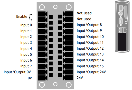
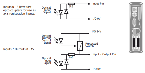
THE MC4N IS GROUNDED VIA THE METAL CHASSIS. FIT A SHORT SHIELD CONNECTION BETWEEN THE CHASSIS EARTH SCREW AND THE EARTHED METAL MOUNTING PANEL / PLATE.
AMPLIFIER ENABLE (WATCHDOG) RELAY OUTPUT
An internal relay may be used to enable external amplifiers when the controller has powered up correctly and the system and application software are ready. The amplifier enable is a single pole solid state relay with a normally open “contact”. The enable relay contact will be open circuit if there is no power on the controller OR an axis error exists OR the user program sets it open with the WDOG=OFF command.
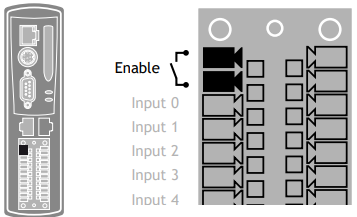
ETHERCAT DRIVES WILL BE ENABLED VIA THE ETHERCAT NETWORK SO THE “AMPLIFIER ENABLE” CONNECTION IS NOT NORMALLY REQUIRED.
ALL NON ETHERCAT STEPPER AND SERVO AMPLIFIERS MUST BE INHIBITED WHEN THE AMPLIFIER ENABLE OUTPUT IS OPEN CIRCUIT
AN ADDITIONAL SAFETY RELAY MAY BE REQUIRED SO AS TO MEET MACHINE SAFETY APPROVALS.
5 WAY CAN CONNECTOR
This is a 5 way 3.5mm pitch connector. The connector is used both to provide the 24 Volt power to the MC4N CAN circuit and provide connections for I/O expansion via Trio’s CAN I/O expanders. A 24V dc, Class 2 transformer or power source should be used.
This 24 Volt input is internally isolated from the I/O 24 Volts and main 24V power.
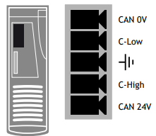
The CAN connector may be left unused.
DISPLAY
The IP address and subnet mask of the MC4N is shown on the LCD display for a few seconds after power-up. The factory default IP address is 192.168.0.250. This can be changed using the IP _ ADDRESS commands via the Motion Perfect software tool.
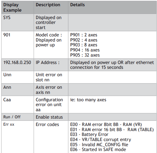
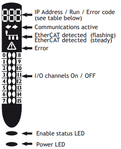
COMMUNICATIONS ACTIVE
This symbol appears when the firmware has detected one or more valid EtherCAT nodes on the network.
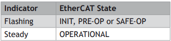
ETHERCAT DETECTION
This symbol shows the EtherCAT connection status.
ERROR
This symbol shows when an error condition has occurred. See the numerical display for more information.
NETWORK SET-UP
NETWORK CONNECTION
Set IP _ ADDRESS in MC4N to an available unused address. It MUST match the subnet in use. Set the PC to use DHCP server.
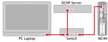
The MC4N always has a fixed IP _ ADDRESS.
POINT-TO-POINT OR CLOSED NETWORK
(No DHCP server)
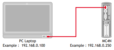
THE PC MUST BE SET TO A FIXED IP _ ADDRESS.
The first 3 “octets” MUST be the same as the MC4N and the last MUST be different, but not 000, 254 or 255.
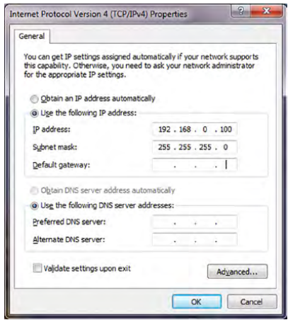
SETTING A FIXED IP ADDRESS
In Windows 7. Open “Network and Sharing Centre” then change “Adapter Settings”. Select the properties of the Local Area Network and the IPv4 properties. The IP Address is set to 192.168.0.100 with subnet mask set to 255.255.255.0. Assuming that the MC4N has IP _ ADDRESS=192.168.0.250 or similar.
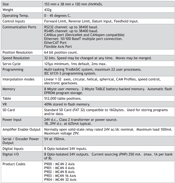
MC4N FEATURE SUMMARY
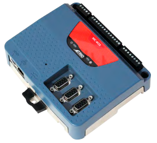
Motion Coordinator MC403
OVERVIEW
The Motion Coordinator MC403 is based on Trio’s highperformance ARM11 double-precision technology and provides 2 axes of servo plus a master encoder axis, or 3 axes of pulse+direction control for stepper drives or pulseinput servo drives. Trio uses advanced FPGA techniques to
reduce the size and fit the pulse output and servo circuitry in a compact DIN-rail mounted package. The MC403 is housed in a rugged plastic case with integrated earth chassis and incorporates all the isolation circuitry necessary for direct connection to external equipment in an industrial environment. Filtered power supplies are included so that it can be powered from the 24V d.c. logic supply present in most industrial cabinets.
It is designed to be configured and programmed for the application using a PC running Trio’s Motion Perfect application software, and then may be set to run “standalone” if an external computer is not required for the final system. Programs and data are stored directly to Flash memory, thus eliminating the need for battery backed storage.
The Multi-tasking version of TrioBASIC for the MC403 allows up to 6 TrioBASIC programs to be run simultaneously on the controller using pre-emptive multi-tasking. In addition, the operating system software includes a the IEC 61131-3 standard run-time environment (licence key required).
A reduced functionality version, the MC403-Z has all the fesatures of the full MC403 except that there are no analogue outputs and the encoder function of axes 0 and 1 is incremental encoder only.
PROGRAMMING
The Multi-tasking ability of the MC403 allows parts of a complex application to be developed, tested and run independently, although the tasks can share data and motion control hardware. The 6 available tasks can be used for TrioBASIC or IEC 61131-3 programs, or a combination of both can be run at the same time, thus allowing the programmer to select the best features of each.
I/O CAPABILITY
The MC403 has 8 built in 24V inputs and 4 bi-directional I/O channels. These may be used for system interaction or may be defined to be used by the controller for end of travel limits, registration, datuming and feedhold functions if required. The MC403 can have up 512 external Input and Output channels connected using DIN rail mounted CAN I/O modules. These units connect to the built-in CANbus port.
COMMUNICATIONS
A 10/100 base-T Ethernet port is fitted as standard and this is the primary communications connection to the MC403. Many protocols are supported including Telnet, Modbus TCP, Ethernet IP and TrioPCMotion. Check the Trio website (www.triomotion.com) for a complete list.
The MC403 has one built in RS232 port and one built in duplex RS485 channel for simple factory communication systems. Either the RS232 port or the RS485 port may be configured to run the Modbus or Hostlink protocol for PLC or HMI interfacing.
If the built-in CAN channel is not used for connecting I/O modules, it may optionally be used for CAN communications. E.g. DeviceNet, CANopen etc.
REMOVABLE STORAGE
The MC403 has a micro-SD Card slot which allows a simple means of transferring programs, firmware and data without a PC connection. Offering the OEM easy machine replication and servicing.
The memory slot is compatible with a wide range of micro-SD cards up to 16Gbytes using the FAT32 compatible file system.
AXIS POSITIONING FUNCTIONS
The motion control software receives instructions to move an axis or axes from the TrioBASIC or IEC 61131-3 language which is running concurrently on the same processor. The motion generation software provides control during operation to ensure smooth, coordinated movements with the velocity profiled as specified by the controlling program. Linear interpolation may be performed on groups of axes, and circular, helical or spherical interpolation in any two/three orthogonal axes. Each axis may run independently or they may be linked in any combination using interpolation, CAM profile or the electronic gearbox facilities.
Consecutive movements may be merged to produce continuous path motion and the user may program the motion using programmable units of measurement (e.g. mm, inches, revs etc.). The module may also be programmed to control only the axis speed. The positioner checks the status of end of travel limit switches which can be used to cancel moves in progress and alter program execution.
CONNECTIONS TO THE MC403
ETHERNET PORT CONNECTION
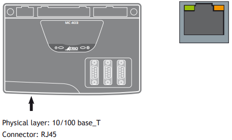
The Ethernet port is the default connection between the Motion Coordinator and the host PC running the Motion Perfect development application.
To reset the IP _ ADDRESS, IP _ GATEWAY and IP _ NETMASK to their default values press the IP reset button and power cycle the controller while keeping the button pressed.
MC403 SERIAL CONNECTIONS
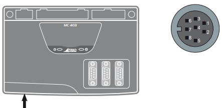
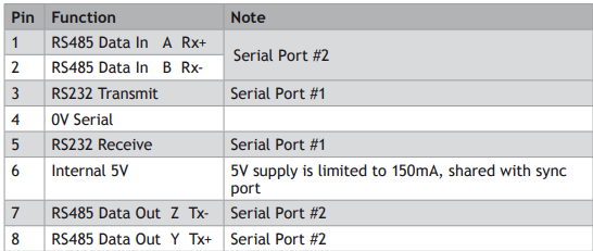
The MC403 features two serial ports. Both ports are accessed through a single 8 pin connector.
SERIAL CONNECTOR
MC403 PULSE OUTPUTS / ENCODER INPUTS
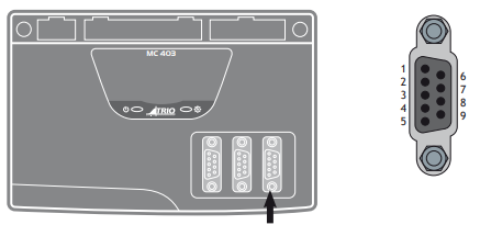
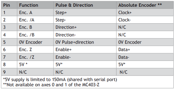
The MC403 is designed to support any combination of servo and pulse input motor drives on the standard controller hardware. The MC403 has 3 versions: 1 axis servo, 2 axis servo and pulse output only. There are also 2 versions of the MC403-Z: 2 axis pulse output and 3 axis pulse output.
Each of the first two axes (0-1) can be enabled as servo(1), pulse and direction or encoder according to the user’s requirements by setting the axis ATYPE parameter. Axis 2 can be set as either pulse+direction or encoder in all versions.
The function of the 9-pin ‘D’ connectors will be dependent on the specific axis configuration which has been defined. If the axis is setup as a servo or encoder, the connector will provide the encoder input. If the axis is configured as a pulse+direction, the connector provides differential outputs for step/direction and enable signals.
The encoder port also provides a current-limited 5V output capable of powering most encoders. This simplifies wiring and eliminates external power supplies.
(1) Servo versions of the MC403 only.
REGISTRATION
Each MC403 encoder port has 2 available registration events. These are assigned in a flexible way to any of the 8 digital inputs or can be used with the Z mark input on the encoder port.
5-WAY CONNECTOR
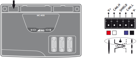
This is a 5 way 3.5 mm pitch connector. The connector is used both to provide the 24 Volt power to the MC403 and provide connections for I/O expansion via Trio’s digital and analogue CAN I/O expanders. 24 Volts must be provided as this powers the unit.
This 24 Volt input is internally isolated from the I/O 24 Volts and the +/-10V Voltage outputs.
24V d.c., Class 2 transformer or power source required for UL compliance. The MC403 is grounded via the metal chassis. It MUST be installed on an unpainted metal plate or DIN rail which is connected to earth. An earth screw is also provided on the rear of the chassis for bonding the MC403 to ground.
I/O CONNECTOR 1
24V INPUT CHANNELS
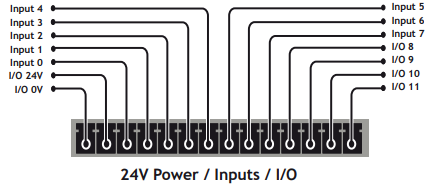
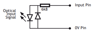
The MC403 has 8 dedicated 24V Input channels built into the master unit. A further 256 inputs can be provided by the addition of CAN I/O modules. The dedicated input channels are labelled channels 0..7.
Inputs 0 to 7 can be used as registration inputs for axes 0 to 2, using the REGIST command.
I/O POWER INPUTS
The I/O 0 Volts (I/O-) and I/O 24 Volts (I/O+) are used to power the 24 Volt digital IO and the analogue I/O, including the servo DAC outputs.
The digital I/O connections are isolated from the module power inputs. The analogue inputs and outputs are isolated from the digital I/O and the module power inputs.
24V I/O CHANNELS
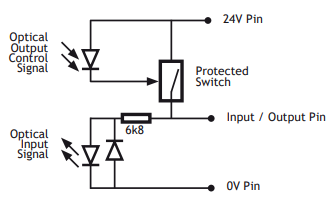
Input/output channels 8..11 are bi-directional. The inputs have a protected 24V sourcing output connected to the same pin. If the output is unused it may be used as an input in the program. The input circuitry is the same as on the dedicated inputs. The output circuit has electronic over-current protection and thermal protection which shuts the output down when the current exceeds 250mA.
Care should be taken to ensure that the 250mA limit for each output circuit is not exceeded, and that the total load for the group of 4 outputs does not exceed 1 amp.
I/O CONNECTOR 2
AMPLIFIER ENABLE (WATCHDOG) RELAY OUTPUTS
An internal relay contact is available to enable external amplifiers when the controller has powered up correctly and the system and application software is ready. The amplifier enable is a solid-state relay with an ON resistance of 25Ω at 100mA. The enable relay will be open circuit if there is no power on the controller OR a motion error exists on a servo axis OR the user program sets it open with the WDOG=OFF command.
The amplifier enable relay may, for example, be incorporated within a hold-up circuit or chain that must be intact before a 3-phase power input is made live.
ALL STEPPER AND SERVO AMPLIFIERS MUST BE INHIBITED WHEN THE AMPLIFIER ENABLE OUTPUT IS OPEN CIRCUIT
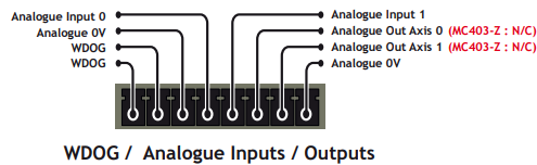
ANALOGUE INPUTS
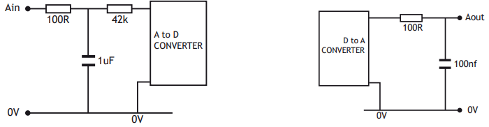
Two built-in 12 bit analogue inputs are provided which are set up with a scale of 0 to 10V. External connection to these inputs is via the 2-part terminal strip I/O connector 2. A 24V d.c. supply must be applied to I/O connector 1 to provide power for the analogue input circuit.
ANALOGUE OUTPUTS
The MC403 has 2 12-bit analogue outputs scaled at +/-10V. Each output is assigned to one servo axis, or in the case where the axis is not used, or is set as a pulse+direction/simulated encoder output, the analogue output may be set to a voltage directly in software. A 24V d.c. supply must be applied to I/O connector 1 to provide power for the analogue output circuit.
The MC403-Z does not have any analogue outputs.
LED DISPLAY
On power-up, the LEDs flash to show the MC403 version and the SD card status.
P821 2 axis pulse output MC403-Z: 3 flashes of the RED LED.
P822 3 axis pulse output MC403-Z 3 flashes of both LEDs alternately.
P823 3 axis pulse output version: 3 flashes of the RED LED.
P824 2 axis servo version: 3 flashes of both LEDs alternately.
P825 1 axis servo version: 3 flashes of the GREEN LED.
SD card loading system software: Both LEDs flash together until the system SW load is completed.
During operation, the two LED’s show the processor (OK) and system status

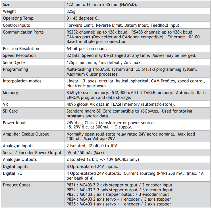
MC403 FEATURE SUMMARY
MC403 AXIS CONFIGURATION SUMMARY
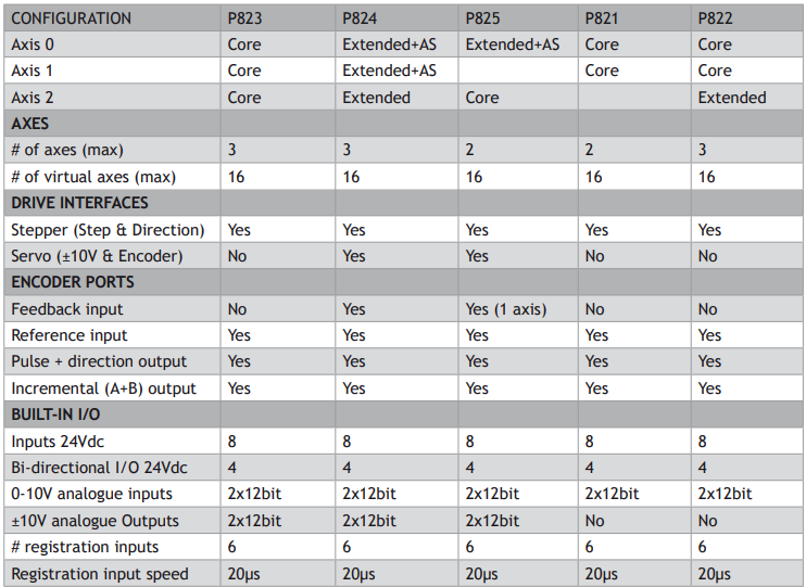
CONFIGURATION KEY
CORE FUNCTIONALITY
CORE AXES – can be configured in software as pulse and direction outputs with stepper or servo drives. They can also be configured for incremental encoder feedback.
Core functionality is a set of ATYPEs (Axis TYPEs) that are available on all controllers. They are based on pulse outputs and incremental encoder feedback.
ATYPE Description
43 Pulse and direction output with enable output
45 Quadrature encoder output with enable output
63 Pulse and direction output with Z input
64 Quadrature encoder output with Z input
76 Incremental encoder with Z input
78 Pulse and direction with VFF _ GAIN and enable output 1
EXTENDED FUNCTIONALITY
EXTENDED AXES – in addition to the Core functionality these axes can also be configured for absolute encoders and closed loop servos (requires voltage output).
ANALOGUE SERVO - Only axes marked as AS have an analogue output and can be used for closed loop control.
All Extended Axes can use these ATYPE’s as feedback.
If you want to just use the feedback and not complete a closed loop servo system set SERVO = OFF
ATYPE Description
30 Analogue feedback Servo
44 Incremental encoder Servo with Z input
46 Tamagawa absolute Servo
47 Endat absolute Servo
48 SSI absolute Servo
60 Pulse and direction feedback Servo with Z input
77 Incremental encoder Servo with enable output
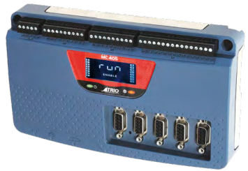
Motion Coordinator MC405
OVERVIEW
The Motion Coordinator MC405 is based on Trio’s high-performance ARM11 double-precision technology and provides 4 axes of servo plus a master encoder axis, or 5 axes of pulse+direction control for stepper drives or pulse-input servo drives. Trio uses advanced FPGA techniques to reduce the size and fit the pulse output and servo circuitry in a compact DIN-rail mounted package. The MC405 is housed in a rugged plastic case with integrated earth chassis and incorporates all the isolation circuitry necessary for direct connection to external equipment in an industrial environment. Filtered power supplies are included so that it can be powered from the 24V d.c. logic supply present in most industrial cabinets. It is designed to be configured and programmed for the application using a PC running Trio’s Motion Perfect application software, and then may be set to run “standalone” if an external computer is not required for the final system. Programs and data are stored directly to FLASH memory, thus eliminating the need for battery backed storage.
The Multi-tasking version of TrioBASIC for the MC405 allows up to 10 TrioBASIC programs to be run simultaneously on the controller using pre-emptive multi-tasking. In addition, the operating system software includes a the IEC 61131-3 standard run-time environment (licence key required).
PROGRAMMING
The Multi-tasking ability of the MC405 allows parts of a complex application to be developed, tested and run independently, although the tasks can share data and motion control hardware. The 10 available tasks can be used for TrioBASIC or IEC 61131-3 programs, or a combination of both can be run at the same time, thus allowing the programmer to select the best features of each.
I/O CAPABILITY
The MC405 has 8 built in 24V inputs and 8 bi-directional I/O channels. These may be used for system interaction or may be defined to be used by the controller for end of travel limits, registration, datuming and feedhold functions if required. Each of the Input/Output channels has a status indicator to make it easy to check them at a glance. The MC405 can have up 512 external Input and Output channels connected using DIN rail mounted CAN I/O modules. These units connect to the built-in CANbus port.
COMMUNICATIONS
A 10/100 base-T Ethernet port is fitted as standard and this is the primary communications connection to the MC405. Many protocols are supported including Telnet, Modbus TCP, Ethernet IP and TrioPCMotion. Check the Trio website (www.triomotion.com) for a complete list.
The MC405 has one built in RS232 port and one built in duplex RS485 channel for simple factory communication systems. Either the RS232 port or the RS485 port may be configured to run the Modbus or Hostlink protocol for PLC or HMI interfacing.
If the built-in CAN channel is not used for connecting I/O modules, it may optionally be used for CAN communications. E.g. DeviceNet, CANopen etc.
REMOVABLE STORAGE
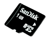
The MC405 has a micro-SD Card slot which allows a simple means of transferring programs, firmware and data without a PC connection. Offering the OEM easy machine replication and servicing.
The memory slot is compatible with a wide range of micro-SD cards up to 2Gbytes using the FAT32 compatible file system.
AXIS POSITIONING FUNCTIONS
The motion control generation software receives instructions to move an axis or axes from the TrioBASIC or IEC 61131-3 language which is running concurrently on the same processor. The motion generation software provides control during operation to ensure smooth, coordinated movements with the velocity profiled as specified by the controlling program. Linear interpolation may be performed on groups of axes, and circular, helical or spherical interpolation in any two/three orthogonal axes. Each axis may run independently or they may be linked in any combination using interpolation, CAM profile or the electronic gearbox facilities.
Consecutive movements may be merged to produce continuous path motion and the user may program the motion using programmable units of measurement (e.g. mm, inches, revs etc.). The module may also be programmed to control only the axis speed. The positioner checks the status of end of travel limit switches which can be used to cancel moves in progress and alter program execution.
CONNECTIONS TO THE MC405
ETHERNET PORT CONNECTION
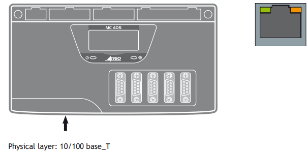
CONNECTOR: RJ45
The Ethernet port is the default connection between the Motion Coordinator and the host PC running the Motion Perfect development application.
MC405 SERIAL CONNECTIONS
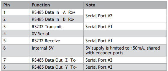
The MC405 features two serial ports. Both ports are accessed through a single 8 pin connector.
SERIAL CONNECTOR

MC405 PULSE+DIRECTION OUTPUTS / ENCODER INPUTS
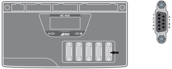
The MC405 is designed to support any combination of servo and pulse driven motor drives on the standard controller hardware. There are 2 versions of the MC405; the servo version and the pulse output only version.
In the pulse output only version, only axis 4 can be configured as an encoder input.
Each of the first four axes (0-3) can be enabled as servo(1), pulse output or encoder(1) according to the user’s requirements by setting the axis ATYPE parameter. Axis 4 can be set as either pulse output, encoder output or encoder input on all versions.
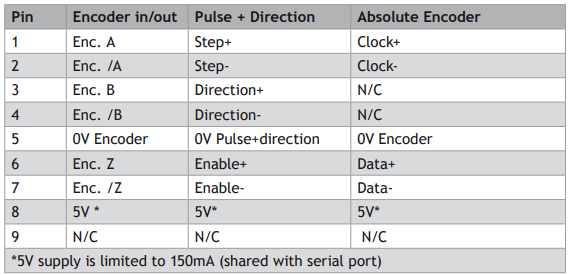
The function of the 9-pin ‘D’ connectors will be dependent on the specific axis configuration which has been defined. If the axis is setup as a servo, the connector will provide the encoder input(1). If the axis is configured as a pulse output, the connector provides differential outputs for step/direction or simulated encoder, and enable signals.
The encoder port also provides a current-limited 5V output capable of powering most encoders. This simplifies wiring and eliminates external power supplies.
(1) Servo version of the MC405 only
REGISTRATION
Each MC405 encoder port has 2 available registration events. These are assigned in a flexible way to any of the 8 digital inputs or can be used with the Z mark input on the encoder port.
5-WAY CONNECTOR
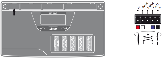
This is a 5 way 3.5 mm pitch connector. The connector is used both to provide the 24 Volt power to the MC405 and provide connections for I/O expansion via Trio’s digital and analogue CAN I/O expanders. 24 Volts must be provided as this powers the unit.
This 24 Volt input is internally isolated from the I/O 24 Volts and the +/-10V voltage outputs.
24V d.c., Class 2 transformer or power source required for UL compliance. The MC405 is grounded via the metal chassis. It MUST be installed on an unpainted metal plate or DIN rail which is connected to earth. An earth screw is also provided on the rear of the chassis for bonding the MC405 to ground.
I/O CONNECTOR 1
I/O CONNECTOR 2
24V INPUT CHANNELS
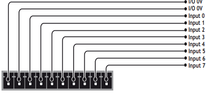
The MC405 has 8 dedicated 24V Input channels built into the master unit. A further 256 inputs can be provided by the addition of CAN I/O modules. The dedicated input channels are labelled channels 0..7. Two terminals marked IN- are provided for the input 0V common connections.
Inputs 0 to 7 can be used as registration inputs for axes 0 to 4, using the REGIST command.
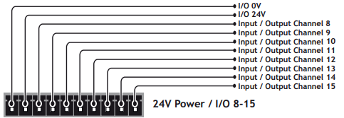
I/O POWER INPUTS
The I/O 0 Volts (I/O-) and I/O 24 Volts (I/O+) are used to power the 24 Volt digital IO and the analogue I/O, including the servo DAC outputs.
The digital I/O connections are isolated from the module power inputs. The analogue inputs and outputs are isolated from the digital I/O and the module power inputs.
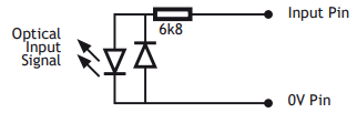
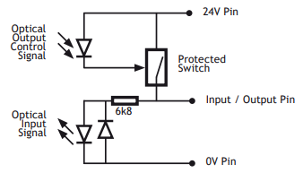
24V I/O CHANNELS
Input/output channels 8..15 are bi-directional. The inputs have a protected 24V sourcing output connected to the same pin. If the output is unused it may be used as an input in the program. The input circuitry is the same as on the dedicated inputs. The output circuit has electronic over-current protection and thermal protection which shuts the output down when the current exceeds 250mA.
Care should be taken to ensure that the 250mA limit for each output circuit is not exceeded, and that the total load for the group of 8 outputs does not exceed 1 amp.
I/O CONNECTOR 3
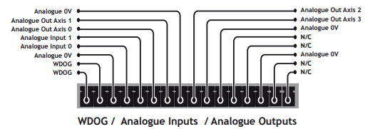
AMPLIFIER ENABLE (WATCHDOG) RELAY OUTPUTS
An internal relay contact is available to enable external amplifiers when the controller has powered up correctly and the system and application software is ready. The amplifier enable is a solid-state relay with an ON resistance of 25Ω at 100mA. The enable relay will be open circuit if there is no power on the controller OR a motion error exists on a servo axis OR the user program sets it open with the WDOG=OFF command.
The amplifier enable relay may, for example, be incorporated within a hold-up circuit or chain that must be intact before a 3-phase power input is made live.
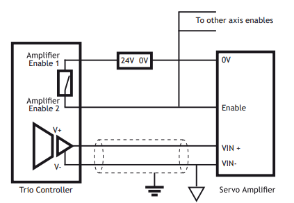
ALL STEPPER AND SERVO AMPLIFIERS MUST BE INHIBITED WHEN THE AMPLIFIER ENABLE OUTPUT IS OPEN CIRCUIT
ANALOGUE INPUTS
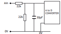
Two built-in 12 bit analogue inputs are provided which are set up with a scale of 0 to 10V. External connection to these inputs is via the 2-part terminal strip I/O connector 3.
A 24V d.c. supply must be applied to I/O connector 2 to provide power for the analogue input circuit.
ANALOGUE OUTPUTS
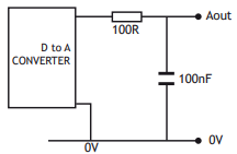
The MC405 has 4 12-bit analogue outputs scaled at +/-10V. Each output is assigned to one servo axis, or in the case where the axis is not used, or is set as a pulse+direction/simulated encoder output, the analogue output may be set to a voltage directly in software.
A 24V d.c. supply must be applied to I/O connector 2 to provide power for the analogue output circuit.
BACKLIT DISPLAY
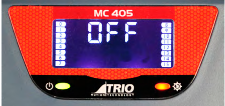
On power-up, the information display area shows bt during the boot process, then the MC405 version is displayed, showing P826 for the 5 axis pulse output version and P827 for the 4 axis servo version. The IP address and subnet mask is shown on power-up and whenever an Ethernet cable is first connected to the MC405.
During operation, this display shows run, Off or Err to indicate the MC405 status. Below the main status display are the ERROR and ENABLE indicators.
ERROR: An error has occurred (see Error Display Codes table below for details).
ENABLE: When illuminated, WDOG is ON.
A bank of 8 indicators at the left side shows the Digital Input States and a similar bank on the right shows the state of I/O8 to I/O15. The I/O displayed can be altered using the DISPLAY command.
Two LED’s are provided to show the processor (OK) and system status.
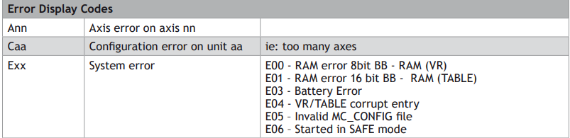
MC405 FEATURE SUMMARY
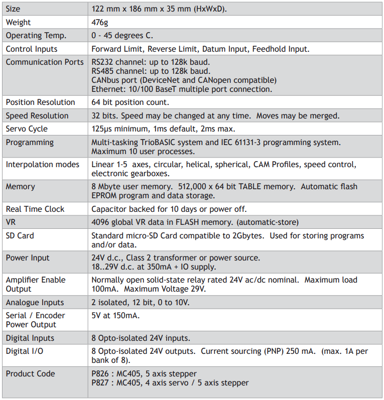
Motion Coordinator Euro404 /408
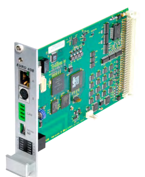
OVERVIEW
The Motion Coordinator Euro404 and Euro408 are Eurocard stepper/servo positioners with the built-in ability to control up to 8 servo or stepper motors in any combination. The Euro404 / 408 is designed to provide a powerful yet cost-effective control solution for OEM machine builders who are prepared to mount the unit and provide the power supplies required. It is designed to be configured and programmed for the application with TrioBASIC or IEC61131-3 standard languages using a PC. It may then may be set to run “standalone” if an external computer is not required for the final system. The Multi-tasking version of TrioBASIC for the Euro404 / 408 allows up to 10 TrioBASIC programs to be run simultaneously on the controller using preemptive multi-tasking.
PROGRAMMING
The Multi-tasking ability of the Euro404 / 408 allows parts of a complex application to be developed, tested and run independently, although the tasks can share data and motion control hardware.
I/O CAPABILITY
The Euro404 / 408 has 16 built in 24V inputs and 8 built-in output channels. These may be used for system interaction or may be defined to be used by the controller for end of travel limits, datuming and feedhold functions if required. 8 status LEDs are available which can be set to display the status of banks of inputs or outputs. The Euro404 / 408 can have up to 512 external Input/Output channels, up to 32 analogue input channels and up to 16 analogue output channels connected using DIN rail mounted I/O modules. These units connect to the built-in CAN channel of the Euro404 / 408.
COMMUNICATIONS
The Euro404 / 408 has one Ethernet port for primary communications, one RS-232 port and one RS 485 built in.
The Ethernet port, RS-232 port or the RS485 port may be configured to run the MODBUS protocol for PLC or HMI interfacing. If the built-in CAN channel is not used for connecting I/O modules, it may optionally be used for CAN communications or DeviceNet.
REMOVABLE STORAGE
A micro SD card can be used with the Euro404 / 408 allows a simple means of transferring programs without a PC connection. Offering the OEM easy machine replication and servicing. The Euro404 / 408 supports SD cards up to 16Gbytes. Each Micro SD Card must be pre-formatted using a PC to FAT32 before it can be used in the SD Card Adaptor.
AXIS CONFIGURATION
The Euro404 / 408 is available in 2 configurations. Either as an 8 axis pulse output card or as the full axis servo card.
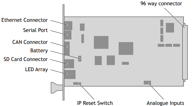
5 VOLT POWER SUPPLY
The minimum connections to the Euro404 / 408 are just the 0V and 5V pins. The Euro404 / 408 is protected against reverse polarity on these pins. Application of more than 5.25 Volts will permanently damage the Motion Coordinator beyond economic repair. All the 0V are internally connected together and all the 5v pins are internally connected together. The 0V pins are, in addition, internally connected to the AGND pins. The Euro404 / 408 has a current consumption of approximately 500mA on the 5V supply. The supply should be filtered and regulated within 5%.
BUILT-IN CAN CONNECTOR
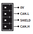
The Euro404 / 408 features a built-in CAN channel. This is primarily intended for Input/ Output expansion via Trio’s CAN I/O modules. It may be used for other purposes when I/O expansion is not required.
EURO404 / 408 BACKPLANE CONNECTOR
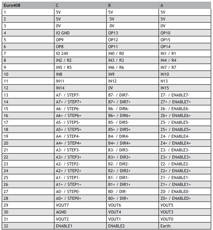
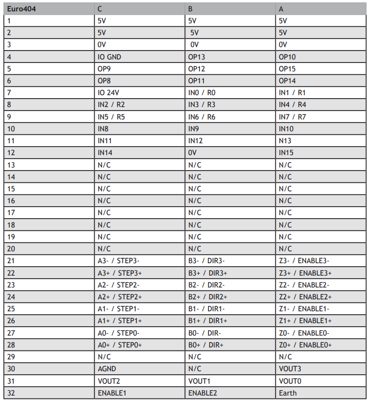
Most connections to the Euro404 / 408 are made via the 96 Way DIN41612 backplane Connector.
AMPLIFIER ENABLE (WATCHDOG) RELAY OUTPUT
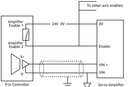
An internal relay contact is used to enable external amplifiers when the controller has powered up correctly and the system and application software is ready. The amplifier enable is a solid-state relay on the Euro404 / 408 with normally open “contacts”. The enable relay will be open circuit if there is no power on the controller OR a following error exists on a servo axis OR the user program sets it open with the WDOG=OFF command. The amplifier enable relay may, for example, be incorporated within a hold-up circuit or chain that must be intact before a 3-phase power input is made live.
Note: all stepper and servo amplifiers MUST be inhibited when the amplifier enable output is open circuit
24V INPUT CHANNELS
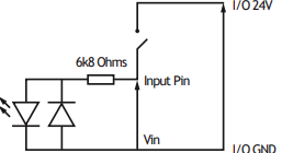
The Motion Coordinator has 16 24V Input channels built into the master unit. These may be expanded to 256 Inputs by the addition of CAN-16 I/O modules.
24V OUTPUT CHANNELS
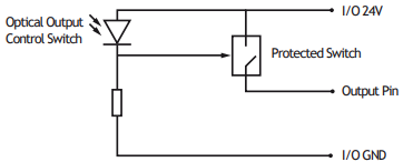
8 output channels are provided. These channels are labelled 8..15 for compatibility with other Motion Coordinators, but are NOT bi-directional as on some Motion Coordinators. Each channel has a protected 24v sourcing output. The output circuit has electronic over-current protection and thermal protection which shuts the output down when the current exceeds 250mA. Care should still be taken to ensure that the 250mA limit for the output circuit is not exceeded, and that the total load for the group of 8 outputs does not exceed 1 amp. Up to 256 further Outputs may be added by the addition of CAN-16I/O modules).
REGISTRATION INPUTS
The registration inputs are 24 Volt isolated inputs that are shared with digital inputs 0 to 7. The Euro404 / 408 can be programmed to capture the position of an encoder axis in hardware when a transition occurs on the registration input.
DIFFERENTIAL ENCODER INPUTS
The encoder inputs on the Euro404 / 408 are designed to be directly connected to 5 Volt differential output encoders. Incremental or absolute encoders can be connected to the ports.
The encoder ports are also bi-directional so that when axes are set to pulse and direction, the encoder port for that axis becomes a Differential output.
Encoder ports and pulse direction ports on the Euro404 / 408 are NOT electrically isolated.
VOLTAGE OUTPUTS
The Euro404 can generate up to 4 +/-10Volt analogue outputs and the Euro408 can generate up to 8 +/- 10Volt analogue outputs for controlling servo-amplifiers. Note that for servo operation the card must be configured as a 4 or 8 axis servo. However, the voltage outputs can be used seperately via the DAC command in TrioBASIC even when the servo axis is not enabled.
ANALOGUE INPUTS
Two built-in 12 bit analogue inputs are provided which are set up with a scale of 0 to 10 Volts. In order to make connection to these inputs, there is a 2 part molex connector behind the front panel. Pin 1 is nearest the front panel.
Pin 1 AIN(32) Mating MOLEX connector part number
Pin 2 AIN(33) Connector housing: 22-01-2035
Pin 3 0V Crimp receptacles : 08-50-0032 (3 required)
USING END OF TRAVEL LIMIT SENSORS
Each axis of the Motion Coordinator system may have a 24v Input channel allocated to it for the functions:
FORWARD Limit Forward end of travel limit
REVERSE Limit Reverse end of travel limit
DATUM Input Used in datuming sequence
FEEDHOLD Input Used to suspend velocity profiled movements until the input is released
Switches used for the FORWARD/REVERSE/DATUM/FEEDHOLD inputs may be normally closed or normally open but the NORMALLY CLOSED type is recommended.
Each of the functions is optional and may be left unused if not required. Each of the 4 functions are available for each axis and can be assigned to any input channel iincluding remote CAN I/O. An input can be assigned to more than one function if desired.
The axis parameters: FWD _ IN,REV _ IN, DATUM _ IN and FH _ IN are used to assign input channels to the functions. The axis parameters are set to -1 if the function is not required.
ETHERNET PORT CONNECTION
Pysical layer: 10/100 baseT
Connector: RJ-45
Connection and activity LED indicators
Fixed IP address
User settable subnet mask and default gateway
DHCP client: Not available (fixed IP only)

A switch is provided on the board to reset the IP address to a known value. To reset to the default value of 192.168.000.250, slide the switch to the left (RST_IP) and power up the Euro404 / 408. Make connection with the Euro404 / 408 using Motion Perfect on the default address and use the IP _ ADDRESS command to set the required address. e.g. for 192.168.000.123 set IP _ ADDRESS=192.168.0.123.
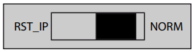
NOTE: The switch also sets the following:
subnet mask to 255.255.255.0
default gateway to 192.168.0.255
Once the IP address has been set, slide switch 1 to NORM and power down the Eurocard. Next time the Euro404 / 408 is powered up, the new IP address can be used.
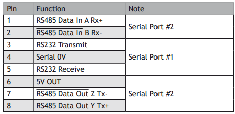
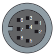
SERIAL CONNECTOR B:
Euro404 / 408 Serial Port Connections
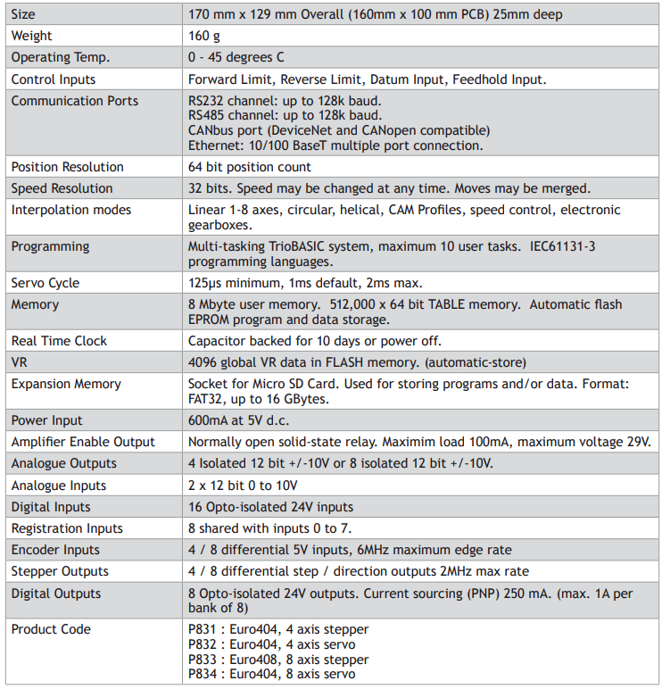
EURO404 / 408 - FEATURE SUMMARY
No comments to display
No comments to display