
4. I/O EXPANSION MODULES
General Description of I/O Modules
Trio Motion Technology’s range of digital and analogue input/output expansion modules are designed to enable simple and scalable I/O extension for Trio’s Motion Coordinators. In addition to 24V input, output and bi-directional modules, there are relay and analogue I/O modules.
The Motion Coordinator I/O expansion system uses CANbus to reduce wiring and allow input/output modules to be distributed remotely. Up to 32 Digital modules and up to 4 Analogue modules may be added to the system.
All CAN Input, Output and I/O modules are DIN rail mounted with the I/O connections located conveniently on the front face. They have been designed with a spaced-saving footprint only 26mm wide so allowing large amounts of Digital and Analogue I/O to be packed in an area no bigger than the average PLC. Address selection is simply done by setting DIP switches that are neatly located under the pull-up flap. LEDs show the I/O state and indicate an error code for straight forward system commissioning and de-bugging.
To install CAN modules, see "Installing the CAN I/O Modules" on page 5-10.
CANbus is used for communication and control between the Motion Coordinator and the CAN I/O modules. CANbus is a tried and tested, well known industrial data link which is reliable, noise immune and flexible. All CAN I/O modules are compatible with any Motion Coordinator that has a CANbus port and they support various CAN protocols.
PRODUCT CODE:
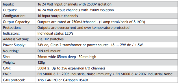
CAN 16-Output Module P317
CAN 16-Input Module P318
CAN 16-I/O Module P319
CAN Analogue I/O Module P326
CAN 8-Relay Module P327
CAN 16-Output Module (P317)
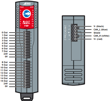
The Trio CAN 16 Output module offers a compact DIN rail mounted relay input expansion capability for all Trio Motion Coordinators. Using remote I/O on the Trio CANbus can significantly reduce the machine wiring.
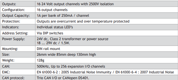
Up to 16 output modules may be connected to the CAN network which may be up to 100m long. This provides up to 256 distributed output channels at 24Vdc level. All outputs are short-circuit proof and completely isolated from the CANbus. P317 modules may be mixed on the same bus, with other types of Trio CAN I/O modules on the same network to build the I/O configuration required for the system.
Convenient disconnect terminals are used for all I/O connections.
CANBUS
The CANbus port has over voltage and reverse polarity protection. Various protocols can selected using the configuration switches.
24V OUTPUT CHANNELS
The P317 has two banks of eight outputs, both banks of outputs are electrically isolated and require their own 24V and 0V. Output channels have a protected 24V sourcing output connected to the output pin. The output circuit has electronic over-current protection and thermal protection which shuts the output down when the current exceeds 250mA.
Care should be taken to ensure that the 250mA limit for the output circuit is not exceeded, and that the total load for the group of 8 outputs does not exceed 1 amp.
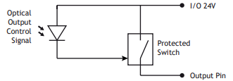
With no load, the outputs may 'float' up to 24V even when of. Fit a load resistor, for example 10k, when bench testing the P317.
LED INDICATORS
The green power (PWR) LED and red error (ERR) LED display the status of the CAN I/O module. The actual status displayed will depend on the protocol selected.
The status LEDs marked 0 - 15 represent the output channels 0 - 15 of the module. The actual outputs as seen by the Motion Coordinator software will depend on the modules’ address.
CONFIGURATION SWITCHES
The switches are hidden under the display window. These can be adjusted to set the module address, protocol and data rate.
SPECIFICATION P317
CAN 16-Input Module (P318)
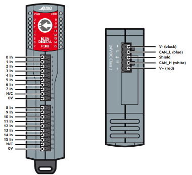
The Trio CAN 16 Input module offers a compact DIN rail mounted relay input expansion capability for all Trio Motion Coordinators. Using remote I/O on the Trio CANbus can significantly reduce the machine wiring.
Up to 16 input modules may be connected to the CAN network which may be up to 100m long. This provides up to 256 distributed input channels at 24Vdc level. All input points are high level (24V in = ON) and completely isolated from the CANbus. P318 modules may be mixed on the same bus, with other types of Trio CAN I/O modules on the same network to build the I/O configuration required for
the system. Convenient disconnect terminals are used for all I/O connections.
CANBUS
The CANbus port has over voltage and reverse polarity protection. Various protocols can selected using the configuration switches.
24V INPUT CHANNELS
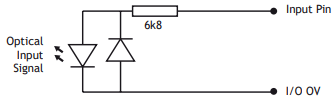
The P318 has two banks of eight inputs, both banks of outputs are electrically isolated and have independent 0V. Input channels are opto-isolated 24V, which are designed to be ON when the input voltage is greater than 18 Volts and OFF when the signal voltage is below 2V. The input has a 6k8 resistor in series and so provides a load of approximately 3.5mA at 24V.
LED INDICATORS
The green power (PWR) LED and red error (ERR) LED display the status of the CAN I/O module. The actual status displayed will depend on the protocol selected.
The status LEDs marked 0 - 15 represent the input channels 0 - 15 of the module. The actual input as seen by the Motion Coordinator software will depend on the modules’ address.
CONFIGURATION SWITCHES
The switches are hidden under the display window. These can be adjusted to set the module address, protocol and data rate.
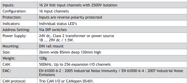
SPECIFICATION P318
CAN 16-I/O Module (P319)
The Trio CAN 16 Input/ Output module offers a compact DIN rail mounted relay input expansion capability for all Trio Motion Coordinators. Using remote I/O on the Trio CANbus can
significantly reduce the machine wiring.
Up to 16 I/O modules may be connected to the CAN network which may be up to 100m long. This provides up to 256 distributed bi-directional input/output channels at 24Vdc level. All input points are high level (24V in = ON) all outputs are short-circuit proof and the I/O is completely isolated from the CANbus. P319 modules may be mixed on the same bus, with other types of Trio CAN I/O modules on the same network to build the I/O configuration required for the system. Convenient disconnect terminals are used for all I/O connections.
CANBUS
The CANbus port has over voltage and reverse polarity protection. Various protocols can selected using the configuration switches.
24V INPUT/ OUTPUT CHANNELS
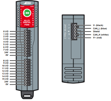
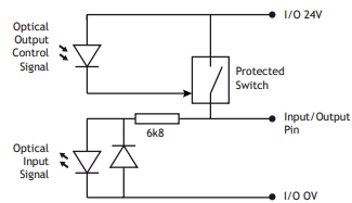
The P319 has two banks of eight bi-directional input/ outputs, both banks are electrically isolated and require their own 24V and 0V. Input/output channels are bi-directional, so can be used as an input or output. Bi-directional inputs have a protected 24V sourcing output connected to the same pin. If the output is unused, the pin may be used as an input in the program. The output circuit has electronic over-current protection and thermal protection which shuts the output down when the current exceeds 250mA.
Care should be taken to ensure that the 250mA limit for the output circuit is not exceeded, and that the total load for the group of 8 outputs does not exceed 1 amp.
LED INDICATORS
The green power (PWR) LED and red error (ERR) LED display the status of the CAN I/O module. The actual status displayed will depend on the protocol selected.
The status LEDs marked 0 - 15 represent the I/O channels 0 - 15 of the module. The actual I/O as seen by the Motion Coordinator software will depend on the modules’ address.
CONFIGURATION SWITCHES
The switches are hidden under the display window. These can be adjusted to set the module address, protocol and data rate.
SPECIFICATION P319
CAN Analogue I/O Module (P326)
The Trio CAN Analogue I/O module offers a compact DIN rail mounted relay output expansion capability for all Trio Motion Coordinators. Using remote I/O on the Trio CANbus can significantly reduce the machine wiring.
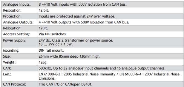
Up to 4 analogue modules may be connected to the CAN network which may be up to 100m long. This provides up to 32 distributed analogue inputs and 16 analogue outputs. Each module provides 8 channels of 12- bit analogue inputs (+/-10v) and 4 channels of 12-bit (+/-10v) analogue outputs. All analogue I/O are completely isolated from the CANbus. P326 modules may be mixed on the same bus, with other types of Trio CAN I/O modules on the same network to build the I/O configuration required for the system.
Convenient disconnect terminals are used for all I/O connections.
CANBUS
The CANbus port has over voltage and reverse polarity protection. Various protocols can selected using the configuration switches.
INPUT TERMINALS
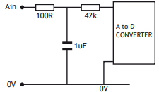
The 8 analogue inputs are single-ended and have a common 0V. Analogue input nominal impedance = 42k Ohm.
OUTPUT TERMINALS
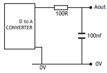
The 4 analogue outputs are single-ended and have a common 0V. Analogue output nominal impedance = 100 Ohm.
The recommended minimum load resistance on the output is 2k Ohm.
LED INDICATORS
The green power (PWR) LED and red error (ERR) LED display the status of the CAN I/O module. The actual status displayed will depend on the protocol selected.
The status LEDs marked 0 - 3 are only used to display an error.
CONFIGURATION SWITCHES
The switches are hidden under the display window. These can be adjusted to set the module address, protocol and data rate.
SPECIFICATION P326
CAN 8-Relay Module (P327)
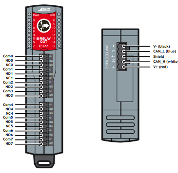
The Trio CAN 8 Relay module offers a compact DIN rail mounted relay output expansion capability for all Trio Motion Coordinators. Using remote I/O on the Trio CANbus can significantly reduce the machine wiring.
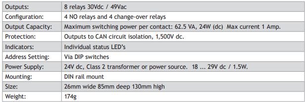
Up to 16 relay modules may be connected to the CAN network which may be up to 100m long. This provides up to 128 distributed low power relay channels at up to 30Vdc or 49Vac. Four of the 8 channels in each module are change-over contact and the remaining four are normally-open contacts. All output points are voltagefree contacts and are completely isolated from the CANbus. P327 modules may be mixed on the same bus, with other types of Trio CAN I/O modules on the same network to build the I/O configuration required for the system.
Convenient disconnect terminals are used for all I/O connections.
0 DO NOT CONNECT 24V AND 0V TO THE BOTTOM TWO PINS (COM3, NO3 AND COM7, NO7) ON THE CONNECTORS AS THE PIN CONNECTIONS ARE DIFFERENT TO THE DETAILS MOLDED INTO THE PLASTIC CASE.
CANBUS
The CANbus port has over voltage and reverse polarity protection. Various protocols can selected using the configuration switches.
RELAY CHANNELS
Each relay channel is an independent isolated voltage free set of contacts. Channels 0, 1, 4 and 5 are change-over contacts and channels 2, 3, 6 and 7 are normally open contacts only. Each contact is rated at 30Vdc (24 Watts) or 49Vac (62.5 VA). Absolute maximum current for any one contact is 1A under all conditions.
Relay contacts do not have built-in suppression so external EMC suppression components must be fitted as required.
USING THE RELAY IN A CIRCUIT WHERE THE RELAY WILL BE ON CONTINUOUSLY FOR LONG PERIODS (WITHOUT SWITCHING) CAN LEAD TO UNSTABLE CONTACTS, BECAUSE THE HEAT GENERATED BY THE COIL ITSELF WILL AFFECT THE INSULATION, CAUSING A FILM TO DEVELOP ON THE CONTACT SURFACES. BE SURE TO USE A FAIL-SAFE CIRCUIT DESIGN THAT PROVIDES PROTECTION AGAINST CONTACT FAILURE OR COIL BURNOUT.
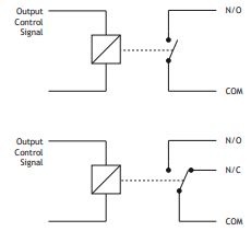
LED INDICATORS
The green power (PWR) LED and red error (ERR) LED display the status of the CAN I/O module. The actual status displayed will depend on the protocol selected.
The status LEDs marked 0 - 7 represent the relay channels 0 - 7 of the module. The actual output as seen by the Motion Coordinator software will depend on the modules’ address.
CONFIGURATION SWITCHES
The switches are hidden under the display window. These can be adjusted to set the module address, protocol and data rate.
SPECIFICATION P327

Controller I/O mapping
DIGITAL I/O ORDER
The controller has different sources of I/O which it has to map to IN and OP. This includes I/O from built in I/O, module I/O and CAN I/O. All of these sources are mapped in blocks of 8, some modules have more than 8 I/O so will take up multiple blocks. Any modules using less than 8 will consume a block of 8 and the remainder of the block will be virtual I/O.
By default built in controller I/O is mapped first followed by module I/O then CAN I/O. MODULE _ IO _ MODE is used to configure a different order or to disable the module I/O. When mapping the blocks of separate input and outputs the controller will overlap any inputs and outputs. Please note that bi directional I/O cannot be split so can cause gaps in the I/O map.
All supported CAN protocols are mapped into the CAN section. For example a system with a MC464, FlexAxis 8, 1 CAN input and 1 CAN output module would be mapped as follows.
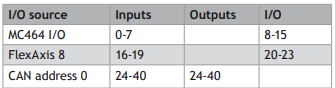
The FlexAxis is mapped to one block of I/O, as only 4 pins are bi-directional, outputs 16-19 are now virtual.
A different system using a MC464, EtherCAT, 1 CAN input and 1 CAN output module would be mapped as follows.
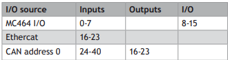
You can see that the EtherCAT inputs and CAN Output module are mapped to the same numbers. It is important to remember that the IN and OP are separate unless they are combined in a bi directional I/O point.
ANALOGUE I/O ORDER
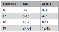
Up to 32 CAN analogue inputs can be added to the system these are mapped to AIN in order of the module address. Analogue inputs are mapped as follows:
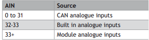
Analogue outputs are mapped to AOUT in order of the module address starting at 0.
TrioCANv2 Protocol
GENERAL DESCRIPTION
The MC4xx range controllers by default will use TrioCANv2 protocol, this has various enhancements of previous versions of TrioCAN. The protocol allows for a combination of current and older CAN I/O modules though not all features of TrioCANv2 will be available if a P325, P315 or P316 module is used.
Enhancements to the protocol allow for the following:
• Increase the number of CAN inputs to 256
• Increase the maximum number of CAN outputs to 256
• Increase the total sum of Inputs and Outputs to 512 (bi-directional I/O counts as 1 input and 1 output)
• Allow new analogue output functionality
• Recognise digital input modules
• Recognise digital output modules
• Allow up to 32 digital modules by overlapping input and output addresses.
• Allow expansion module registration inputs and hardware PSWITCH outputs to be used as I/O
• Improved error handling – any error on the network is reported to the controller
If you need to revert to TrioCANv1 protocol you can set CANIO _ MODE and MODULE _ IO _ MODE. When using CANIO _ MODE=1 all digital input, output and relay modules are treated as bi-directional
I/O modules.
These changes will impact how you address the CAN I/O modules and how the I/O is mapped into the controller.
PROTOCOL SELECTION
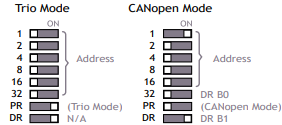
TrioCAN (all versions) can be selected on the CAN I/O modules using the protocol (PR) switch. When the controller initialises the CAN network it will tell the module to either use TrioCANv1 or TrioCANv2. It is recommended to leave the controller using TrioCANv2 however TrioCANv1 can be manually set in the controller using CANIO _ MODE.
The data rate is fixed to 500kHz for TrioCANv2 Protocol, the data rate (DR) switch has no function. It is not possible to mix the CAN I/O modules which are running the TrioCANv2 protocol with DeviceNet equipment or CANopen devices on the same network
CONTROLLER SETUP
All Motion Coordinators are configured by default to look for a TrioCAN network, MC4xx range controllers will automatically use TrioCANv2 if the modules on the network all support it. To force the controller to always use TrioCANv1 you can set CANIO _ MODE.
To automatically search the CAN bus for TrioCAN modules on power up, CANIO _ ADDRESS must be set to 32. There is no need to set this as it is the default value.
There are various system parameters available on the controller to check and change the status of the TrioCAN network, these include CANIO _ STATUS, CANIO _ ADDRESS, CANIO _ ENABLE and CANIO _ MODE.
When choosing which I/O devices should be connected to which channels the following points need to be considered:
• Inputs 0 - 63 ONLY are available for use with system parameters which specify an input, such as FWD _ IN, REV _ IN, DATUM _ IN etc.
• The built-in I/O channels have the fastest operation <1mS
• CAN input modules with addresses 0-3 have the next fastest operation up to 2mS
• The remaining CAN input modules operate up to 20mS
• Outputs are set on demand.
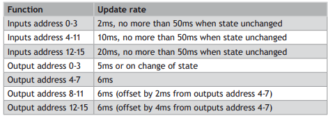
UPDATE RATES
DIGITAL I/O
The digital I/O are cascaded through the modules, this means that lower address modules have a higher update rate.
ANALOGUE I/O
Analogue inputs have a standard operation which is enabled by default. Some applications require higher speed updates for example when using the analogue inputs as feedback into a servo loop.
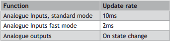
Standard operation is selected by default by the analogue module on power up. Fast operation has to be selected by executing the following BASIC in a configuration or startup program:
CAN(-1, 5, 4, $50, 8 ,1)
CAN(-1, 7, 4, $04, module_address, $00, $20, $00, $00, $00, $01)
DIGITAL CAN I/O ADDRESSING
To enable up to 32 modules on the TrioCANv2 network and up to 512 I/O points Inputs and Outputs are addressed separately. There are 16 addresses (0-15) available for input modules and 16 addresses (0-15) available for outputs. Bi-directional modules take the same address from both the input and output range. There must be no gaps in the input address range, but gaps are allowed in the output address range.
Relay modules are addressed as per digital outputs, they use a block of 16 outputs even though they only have 8.
The total number of digital outputs, digital inputs and total digital I/O are reported by the system parameters NIN, NOP, NIO. The digital configuration is also reported in the startup message.
It is important to remember that IN and OP are only connected if you are using a bi-directional module. When using Input and Output modules with the same address IN(x) and OP(x) can be physically different I/O. If you need to read the state of an output you should use READ _ OP(x).
For example a system with 5 CAN 16-Input, 2 16-IO, 7 16-Output and one Relay module could be mapped as per the table below. The CAN I/O start at 16 as the controller has 16 I/O built-in and no module I/O. The start position will move depending on the number of built in I/O and module I/O.
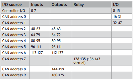
You can see from this chart how the input and output modules are allowed to have overlapping addresses. Bi-directional I/O modules must have a unique address. The relay module only has 8 outputs but uses 1 bank of 16 outputs.
TRIOCAN (V1) TREATS ALL MODULES AS BI-DIRECTIONAL I/O AND SO EVERY MODULE MUST HAVE A UNIQUE ADDRESS. THE TOTAL NUMBER OF I/O POINTS IS LIMITED TO 256 AND THE NETWORK IS LIMITED TO 15 MODULES.
ANALOGUE I/O ADDRESSING
The address switches on the analogue I/O modules will affect the order in which the I/O is mapped into AIN and AOUT. The first analogue module should be address 16 the second to 17 etc, there should be no gaps in the analogue I/O addressing. The addresses are set as a binary sum so for address 17 both switch 16 and 1 must be ON.
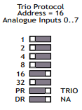
The total number of analogue outputs, analogue inputs and total analogue I/O are reported by the system parameters NAOUT, NAIN, NAIO. The analogue configuration is also reported in the startup message.
The analogue I/O are addressed as per the following table.
ERROR CODES
When there is a problem with the TrioCANv2 network an error code is displayed on the LED’s. All CAN I/O modules have a power LED (PWR) and an error LED (ERR). The power led should be illuminated while the 24V is applied to the CAN connector and the error LED will turn ON when there is an error. The actual error can be read from the status LED’s
You can detect which modules have errors by reading CANIO _ STATUS in the motion coordinator
DIGITAL INPUT, OUTPUT AND I/O MODULES
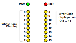
When there is an error the left bank of LED’s will flash and the ERR LED will be ON. The error code will be displayed as a binary number on LED’s 8-11
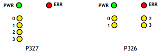
Relay module and Analogue I/O module
When there is an error the error code will be displayed as a binary number on LED’s 0-3 and the ERR LED will be ON.
ERROR CODES
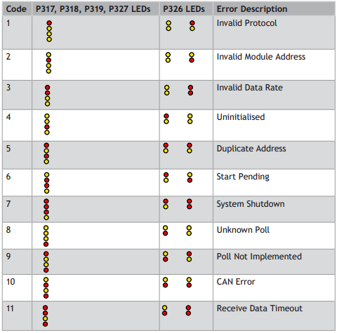
Once the binary number has been read from the CAN I/O LED’s then the error is as per the table below.
Please note that only the error LED's are shown.
TROUBLESHOOTING
If the network configuration is incorrect 2 indications will be seen: The CAN module will indicate an error and the Motion Coordinator will report the wrong number of digital or analogue I/O.
If the error is ‘uninitialised’ then please check:
• Terminating 120 Ohm Network Resistors fitted?
• 24Volt Power to Network?
• Are the addresses correct?
• Have you power cycled the I/O modules after setting the address?
• Cable used is the correct CAN bus specification?
• Is CANIO _ ADDRESS=32?
If the network is OK but you are having I/O problems please check:
• 24Volt Power to each I/O bank required?
• You are using the correct I/O in the controller?
• MODULE _ IO _ MODE is set as you expect?
• CANIO _ MODE is set as you expect?
If the network stops during use please check:
• Terminating 120 Ohm Network Resistors fitted?
• The CAN cable is shielded with the shields correctly connected to earth
Cable used is the correct CAN bus specification?
• Connectors/ wires are not loose
CANopen DS401
GENERAL DESCRIPTION
The CAN modules can support CANopen DS401 so that they can be used with another manufacturers master or with a Trio Motion Coordinator and another manufacturer’s module on the network.
PROTOCOL SELECTION
CANopen is selected on the CAN I/O modules using the protocol (PR) switch on the module.
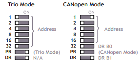
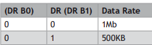
CANopen allows the use of different data rates, this is selected by setting the switches marked 32 and DR. Switch 32 sets bit 0 of the data rate and DR sets bit 1.

CONTROLLER SETUP
To use CANopen DS402 an initialisation program must be run that configures the network. Examples of this program can be found on the Trio website. Once The CANopen network is configured then you can use the CAN I/O with the standard IN, OP, READ _ OP, AIN and AOUT *commands as normal.
(*Future software release)
MODULE ADDRESSING
Each CAN I/O module becomes a node on the CANopen network. The address switches are used to assign a unique node number to the module.
ERROR CODES
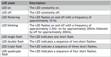
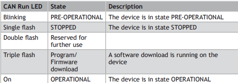
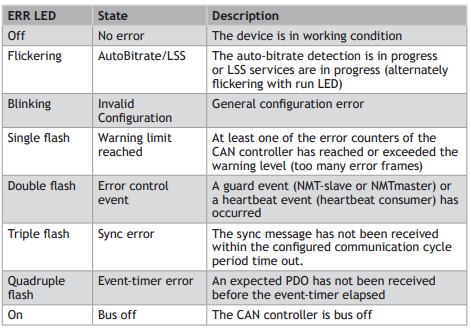
The power (PWR) and error (ERR) LEDs display the modules current state as per the tables below.
LED STATE DEFINITIONS
PWR LED ERROR CODE
The PWR LED is used as the ‘CANopen run LED’ as recommended by CANopen. Its state displays the following:

ERR LED ERROR CODE
The ERR LED is used as the ‘CANopen error LED’ as recommended by CANopen. Its state displays the following:
No comments to display
No comments to display