
6. EMC
EMC Considerations
Most pieces of electrical equipment will emit noise either by radiated emissions or conducted emissions along the connecting wires. This noise can cause interference with other equipment near-by which could lead to that equipment malfunctioning. These sort of problems can usually be avoided by careful wiring and following a few basic rules.
• Mount noise generators such as contactors, solenoid coils and relays as far away as possible from the Motion Coordinator.
• Where possible use solid-state contactors and relays.
• Fit suppressors across coils and contacts.
• Route heavy current power and motor cables away from signal and data cables.
• Ensure all the modules have a secure earth connection.
• Where screened cables are used terminate the screen with a 360 degree termination rather than a “pig-tail”. Connect both ends of the screen to earth. The screening should be continuous, even where the cable passes through a cabinet wall or connector.
These are just very general guidelines and for more specific advice on specific controllers, see the installation requirements later in this chapter. The consideration of EMC implications is more important than ever since the introduction of the EC EMC directive which makes it a legal requirement for the supplier of a product to the end customer to ensure that it does not cause interference with other equipment and that it is not itself susceptible to interference from other equipment.
EMC Earth - MC464
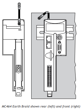
Best EMC performance is obtained when the MC464 is attached to an earthed, unpainted metal panel using the two mounting clips. When screwed directly to the panel, the clips provide the required EMC earth connection.
If the MC464 is mounted on a DIN rail, then an additional EMC earth must be attached as shown below. Use a flat braided conductor, minimum width; 4mm. Connect to the earthed metal panel as close to the MC464 as possible. Do not use circular cross-section wire. Do not run the conductor to a central star point.
EMC Earth – MC405 / MC403
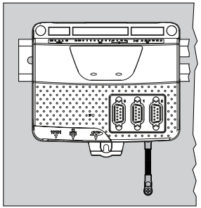
Best EMC performance is obtained when the MC405/MC403 is attached to an earthed, unpainted metal panel using three mounting screws. When screwed directly to the panel, the metal chassis provides the required EMC earth connection.
If the MC405/MC403 is mounted on a DIN rail, then an additional EMC earth must be attached as shown below. Use a flat braided conductor, minimum width 4mm. Connect to the earthed metal panel as close to the Motion Coordinator as possible. Do not use circular cross-section wire. Do not run the conductor to a central star point.
EMC Earth - CAN I/O Modules
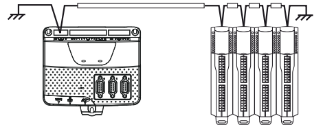
Best EMC performance is obtained when the CAN I/O modules have the screen of the CAN cable connected to the shield pin of the 5 way connector. Both ends of the CAN cable must be connected to an earth point on the back panel of the cabinet. The connection must be as close as possible to the last I/O module. Use a flat braided conductor, minimum width 4mm. Do not use circular cross-section wire. Do not run the conductor to a central star point.
Cable Shields
All encoder cables must be terminated in the correct D-type plug, either 9 way or 15 way as required. For best EMC performance use a metal or metalised plastic cover for the D-type connector. Clamp the screen of the encoder cable where it enters the connector cover. Do not make a “pig-tail” connection from the screen to the plug cover. When plugging the D-type into the MC464, use the jack-screws to firmly attach the D-type plug to the socket on the MC464 or its axis module.
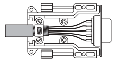
Both ends of the encoder cable’s screen must be connected using a 360 degree contact and not a pigtail connection.
The 0V must be connected separately from the screen. Make sure that encoder cables are specified with one extra wire to carry the 0V.
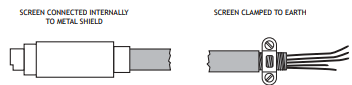
All serial cables must be terminated in an 8-pin mini-DIN connector. For best EMC performance, clamp the screen of the serial cable where it enters the connector cover. Do not make a “pig-tail” connection from the screen to the plug cover.
Both ends of the serial cable’s screen must be connected using a 360 degree contact and not a pig-tail connection. The 0V must be connected separately from the screen. Make sure that serial cables are specified with one extra wire to carry the 0V. This applies to RS422/RS485 serial connections as well as RS232.
Surge protection
This section applies to all devices including Motion Coordinators, CAN IO modules and HMIs. The surge protection described is to enable the system components to comply with EMC Generic Immunity for industrial environments standard IEC 61000-6-2:2005.
SINGLE POWER SUPPLY
Where the device is supplied with 24V dc from one dedicated 24V power source and the connecting cable is less than 3 metres, there is no need for a separate surge protection device.
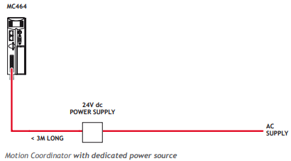
DISTRIBUTED POWER SUPPLY
If the device is connected to a distributed power supply or the cable length between the power source and the device is longer than 3 metres, then a surge protection device must be fitted to comply with the CE EMC directive.
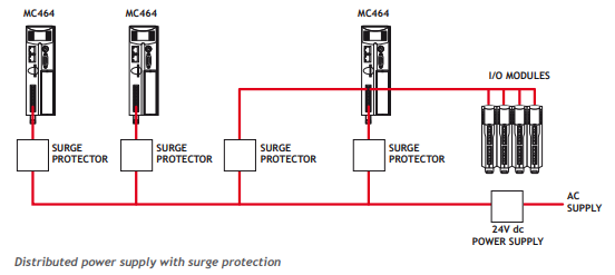
RECOMMENDED PROTECTION DEVICE
If a surge protector is required, a device conforming to the specification below must be installed as close as possible to the 24V power input requiring protection. In addition, the MC405 and MC403 require 2 x 220 µF electrolytic capacitors to complete the protection circuit.
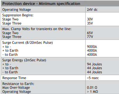
A suggested device is the DC Surge protector TSP-WG6-24VDC-10A-01 from Axiomatic. This protection device is easy to implement with Trio products and is DIN rail mountable. The DC Surge protector and Trio product must be connected to EARTH to make the protection effective.
MC464 AND IO DEVICES
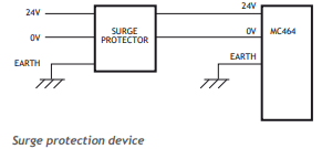
MC403/MC405
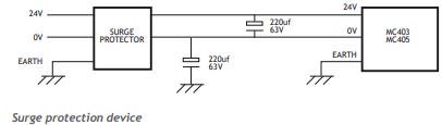
If the I/O power is from a different power source to the main device power, then the I/O power must also have a surge protector fitted.
Background to EMC Directive
Since 1st January 1996 all suppliers of electrical equipment to end users must ensure that their product complies with the 89/336/EEC Electromagnetic Compatibility directive. The essential protection requirements of this directive are:
Equipment must be constructed to ensure that any electromagnetic disturbance it generates allows radio and telecommunications equipment and other apparatus to function as intended.
Equipment must be constructed with an inherent level of immunity to externally generated electromagnetic disturbances.
Suppliers of equipment that falls within the scope of this directive must show “due diligence” in ensuring compliance. Trio has achieved this by having products that it considers to be within the scope of the directive tested at an independent test house.
As products comply with the general protection requirements of the directive they can be marked with the CE mark to show compliance with this and any other relevant directives. At the time of writing this manual the only applicable directive is the EMC directive. The low voltage directive (LVD) which took effect from 1st January 1997 does not apply to current Trio products as they are all powered from 24V which is below the voltage range that the LVD applies to.
Just because a system is made up of CE marked products does not necessarily mean that the completed system is compliant. The components in the system must be connected together as specified by the manufacturer and even then it is possible for some interaction between different components to cause problems but obviously it is a step in the right direction if all components are CE marked.
TESTING STANDARDS
For the purposes of testing, a typical system configuration was chosen because of the modular nature of the Motion Coordinator products. Full details of this and copies of test certificates can be supplied by Trio if required.
For each typical system configuration testing was carried out to the following standards:
EMISSIONS - BS EN61000-6-4 : 2007.
The MC4 range of products conform to the Class A limits.
IMMUNITY - BS EN61000-6-2 : 2005.
This standard sets limits for immunity in an industrial environment and is a far more rigorous test than part 1 of the standard.
REQUIREMENTS FOR EMC CONFORMANCE
WHEN THE TRIO PRODUCTS ARE TESTED THEY ARE WIRED IN A TYPICAL SYSTEM CONFIGURATION. THE WIRING PRACTICES USED IN THIS TEST SYSTEM MUST BE FOLLOWED TO ENSURE THE TRIO PRODUCTS ARE COMPLIANT WITHIN THE COMPLETED SYSTEM.
A summary of the guidelines follows:
The MC464 modules must be earthed via the main chassis of the MC4 range using the lower panel mounting clip or an earth strap. This must be done even if DIN rail mounted.
If any I/O lines are not to be used they should be left unconnected rather than being taken to a terminal block, for example, as lengths of unterminated cable hanging from an I/O port can act as an antenna for noise.
Screened cables MUST be used for encoder, stepper and registration input feedback signals and for the demand voltage from the controller to the servo amplifier if relevant. The demand voltage wiring must be less than 1m long and preferably as short as possible. The screen must be connected to earth at both ends. Termination of the screen should be made in a 360 degree connection to a metallised connector shell. If the connection is to a screw terminal e.g. demand voltage or registration input the screen can be terminated with a short pig-tail to earth.
Ethernet cables should be shielded and as a minimum, meet the TIA Cat 5e requirements.
Connection to the serial ports should be made with a fully screened cable.
As well as following these guidelines, any installation instructions for other products in the system must be observed.
No comments to display
No comments to display