
3. OPERATING MODES
This chapter describes the variables related to the amplifier’s operating modes. Contents include:
3.1: Desired State Variable
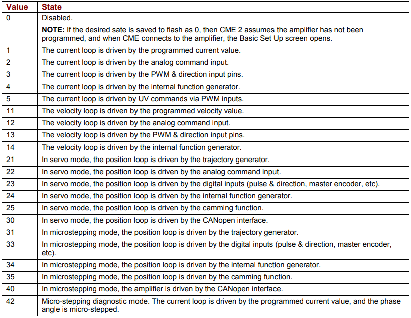
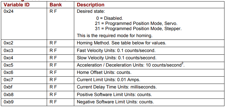
The amplifier desired state variable (0x24) defines the amplifier’s operating mode and which input source controls it. Mode-specific values are mentioned in the remaining sections of this chapter. The relevant values are described in the table below:
3.2: Current Mode
3.2.1: Programmed Current Mode
The Programmed Current Mode sets the output of the amplifier at a programmed current level. When the amplifier is enabled in this mode, or when the programmed current level is changed, the output current ramps to the new level at the programmed rate.
Programmed Current Mode Variables
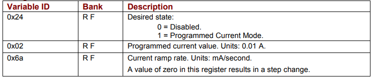
NOTE: When changing both the level and the ramp parameters while the amplifier is enabled, change the ramp rate first.
Programmed Current Mode Example
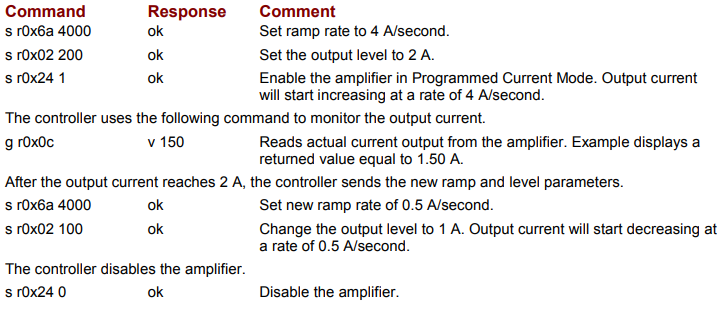
Enable the amplifier in Programmed Current Mode. Ramp the output current up to 2 A in 0.5 seconds. The controller monitors the output current, and after it reaches 2 A the current is ramped down to 1 A in 2 seconds.
3.2.2: Analog Current Mode
In the Analog Current Mode, the current output of the amplifier is proportional to the analog reference input command signal.
Analog Current Mode Variables
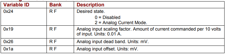
NOTE: Variables 0x19, 0x26 and 0x1a are used in Analog Current, Velocity and Position modes. Verify that these variables are set correctly before switching between these modes of operation.
Analog Current Mode Example
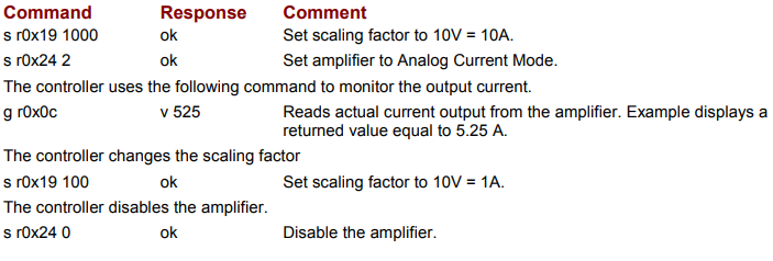
The controller sets the scaling, enables the amplifier in Analog Current Mode, monitors the current output, and changes the scaling to a new value.
3.2.3: PWM Current Mode
In the PWM Current Mode, the current output of the amplifier is proportional to the duty cycle of the input command signal. In most applications the command signal configuration is set using CME 2 and not changed during operation.
PWM Current Mode Variables
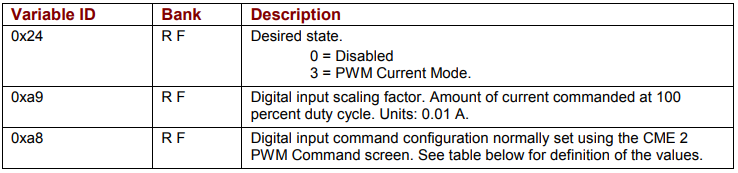
NOTE: Variables 0xa9 and 0xa8 are used in PWM Current and Velocity modes. Verify that these variables are set correctly before switching between these modes of operation.
PWM Current Mode Example
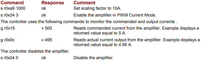
The controller sets the scaling, enables the amplifier in PWM Current Mode, and monitors commanded and actual current.
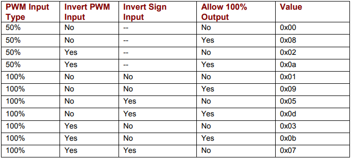
PWM Current Mode Command Signal Configuration
If required during operation, the PWM command signal configuration can be changed by setting the value of variable 0xa8 as shown below
3.3: Velocity Mode
3.3.1: Programmed Velocity Mode
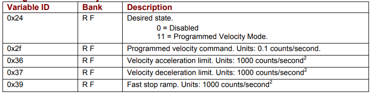
The Programmed Velocity Mode sets the output of the amplifier to a programmed motor velocity. When the amplifier is enabled in this mode, or when the programmed velocity is changed, the motor velocity will ramp to the new level at the programmed rate.
Programmed Velocity Mode Variables
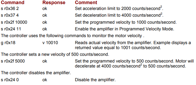
Programmed Velocity Mode Example
The controller sets the velocity parameters, enables the amplifier in Programmed Velocity Mode, monitors the actual motor velocity, and then changes the velocity.
3.3.2: Analog Velocity Mode
In the Analog Velocity Mode, the motor velocity is proportional to the analog reference input command signal.
Analog Velocity Mode Variables
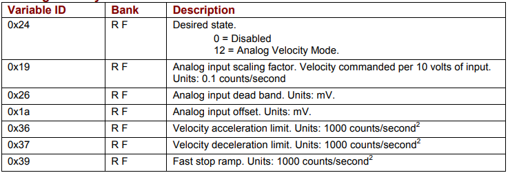
NOTE: Variables 0x19, 0x26 and 0x1a are used in Analog Current, Velocity and Position modes. Verify that these variables are set correctly before switching between these modes of operation.
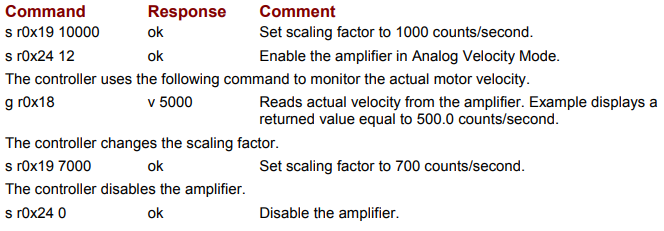
Analog Velocity Mode Example
The controller sets the scaling, enables the amplifier in Analog Velocity Mode, monitors the actual motor velocity, and changes the scaling.
3.3.3: PWM Velocity Mode
In the PWM Velocity Mode, the motor velocity is proportional to the duty cycle of the input command signal. In most applications the command signal configuration is set using CME 2 and not changed during operation.
PWM Velocity Mode Variables
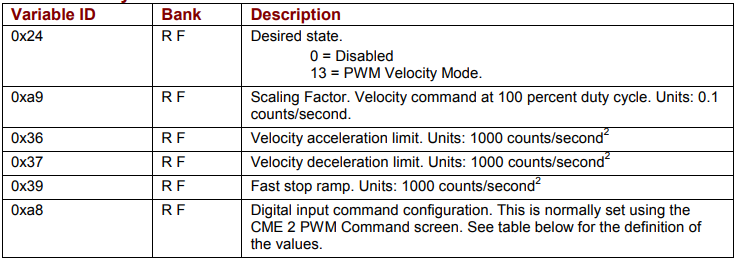
NOTE: Variables 0xa9 and 0xa8 are used in PWM Current and Velocity modes. Verify that these variables are set correctly before switching between these modes of operation.
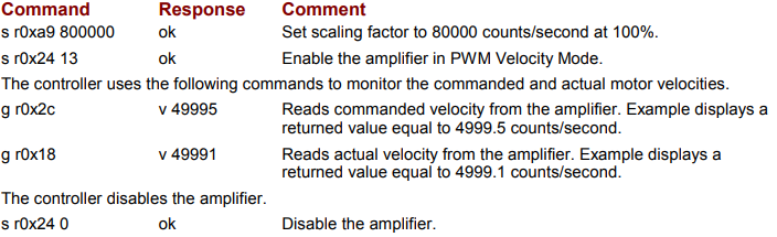
PWM Velocity Mode Example
The controller sets the PWM scaling, enables the amplifier in PWM Velocity Mode, and monitors the commanded and actual velocity.
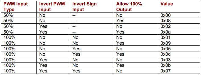
PWM Velocity Mode Command Signal Configuration
If required during operation, the PWM command signal configuration can be changed by setting the value of variable 0xa8 as shown below.
3.4: Position Mode
3.4.1: Updating Trajectory Variables in Position Modes
When the amplifier enters a position mode, the trajectory variables (velocity, acceleration and deceleration) are copied into the trajectory generator. To change any of them after the amplifier is in a position mode, send the new value to the appropriate variable and then send a t 1command.
3.4.2: Programmed Position Mode
In the Programmed Position Mode, the axis moves to target positions sent to the amplifier over the serial interface. The target positions can be absolute or relative from the current position. The motion profile used can be set to trapezoidal or S-curve.
To initiate a move, first set the appropriate variables and then send the trajectory command t 1 to start the move (see Trajectory (t) Generator Command, p. 17). When using the trapezoidal profile, the move parameters can be changed during the move. Again, first set the appropriate variables and then send another t 1 command. When the t 1 command is received, the target position, absolute / relative, velocity, acceleration and deceleration rates will be updated. In this manner, the move in progress can be changed. The S-curve profile cannot be updated in this manner.
To abort a move in progress, send a t 0 command. This will stop the move in progress using the abort deceleration rate. The amplifier will remain enabled.
A special velocity mode can be used to move the axis using the velocity, acceleration and deceleration of the trapezoidal profile but with no specific target position. Direction of motion is set by entering a “1” or “-1” into the position command variable. Once started, the move will continue until the velocity variable is set to zero and a t 1 command is sent or a t 0 abort command is sent.
Programmed Position Mode Variables
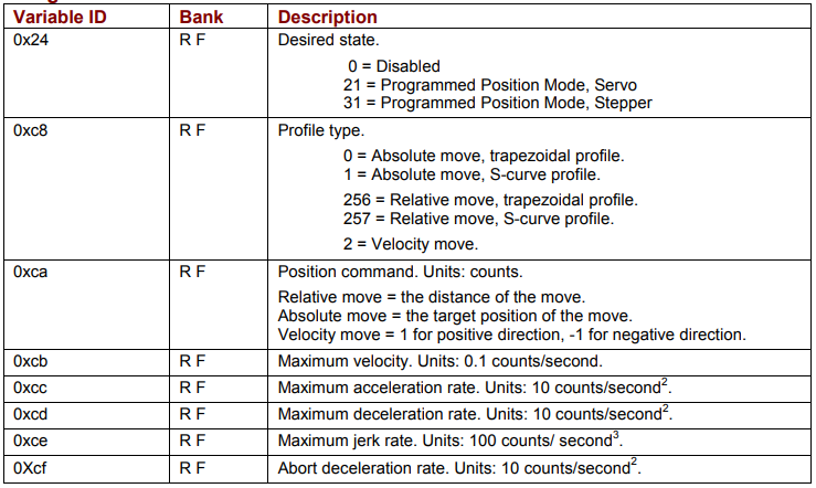
NOTES: 1) Maximum jerk rate is not used in the trapezoidal profile. 2) In the S-curve profile, the maximum deceleration rate is note used. The maximum acceleration rate is used for both acceleration and deceleration.
Programmed Position Mode Example
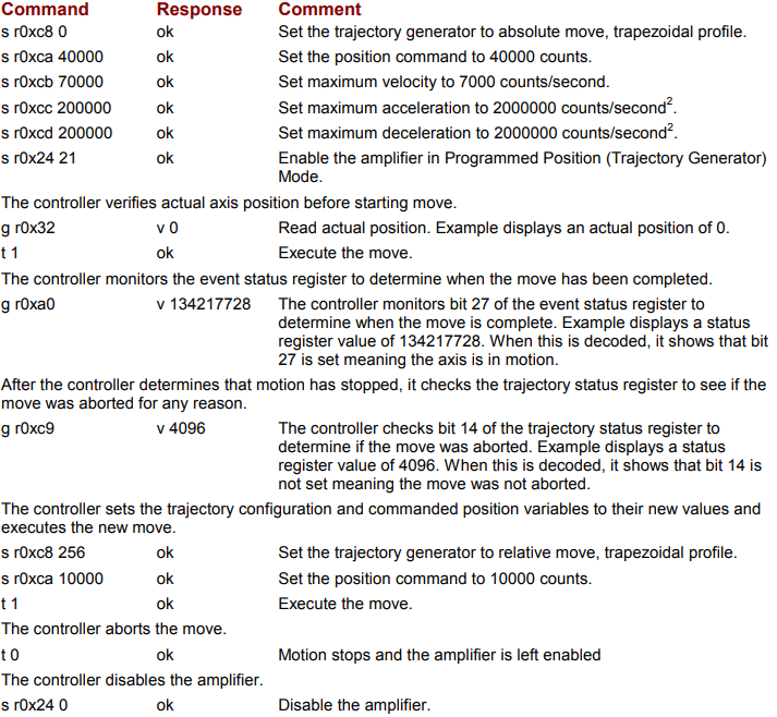
The controller sets profile parameters, executes an absolute trapezoidal move to position 40,000 counts, monitors for move completion, and then executes a relative move of 10,000 counts using the same profile parameters.
3.4.3: Analog Position Mode
In the Analog Position Mode, the axis position is commanded by the analog reference input command signal.
The analog position command operates as a relative motion command. When the amplifier is enabled the voltage on the analog input is read. Then any change in the command voltage will move the axis a relative distance, equal to the change in voltage, from its position when enabled.
To use the analog position command as an absolute position command, the amplifier should be homed every time it is enabled.
Analog Position Mode Variables
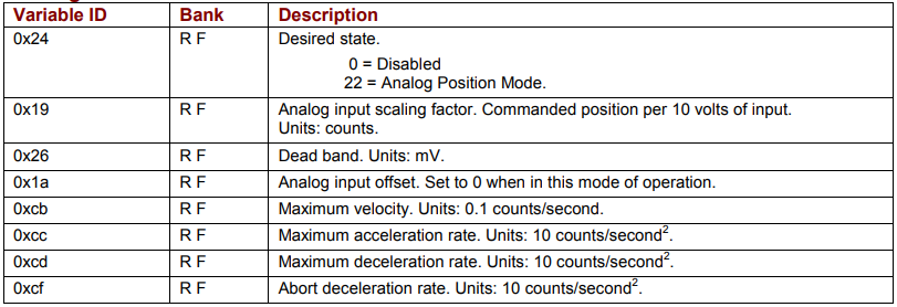
NOTES: 1) Variables 0x19, 0x26 and 0x1a are used in Analog Current, Velocity and Position modes. Verify that these variables are set correctly before switching between these modes of operation. 2) To invert the direction of motion with respect to the polarity of the command voltage, set the scaling factor as a negative value.
Analog Position Mode Example
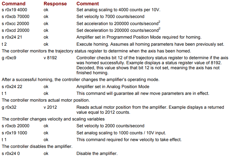
The controller sets the move parameters, homes the axis and then places the amp in the Analog Position Mode. The controller monitors actual position. The controller then changes the maximum velocity and scaling factor.
3.4.4: Pulse and Direction Mode
In the Pulse and Direction Position Mode, the axis position is commanded by pulses applied to one of the amplifiers digital inputs. The direction of the commanded move is determined by the logic level of a second digital input.
The scaling factor sets the ratio of position command, in counts, for each input pulse. This ratio is stored in variable 0xa9 as two 16 bit words. The first word stores the numerator or number of position counts. The second stores the denominator or the number of input pulses.
Example: To set a ratio of 10 counts of position change for every input pulse. The ration would be 10/1. To make sending the data easier, it should be converted to hex word format so the ratio would now be 0x000a / 0x0001. The two words can now simply be combined and sent to the amplifier by sending the command s r0xa9 0x000a0001.
To invert the direction, the numerator should be set to a negative value.
Example: Changing direction of the previous example would require a ratio of -10/1. Using the 2’s complement method, -10 is represented as 0xfff6 hex. The ratio in hex would now be 0xfff6 / 0x001. Combining these words, the command to be sent would be s r0xa9 0xfff60001.
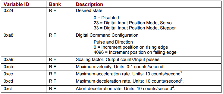
Pulse and Direction Mode Variables
Pulse and Direction Mode Example
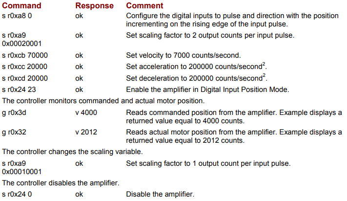
The controller sets the move parameters, places the amp in the Pulse and Direction Position Mode, monitors commanded and actual position, and then changes the scaling factor
3.4.5: Pulse Up/Down Mode
In the Pulse Up/Down Position Mode, the axis position is commanded by pulses applied to the amplifiers digital inputs. The direction of the commanded move is determined by which of the digital inputs the pulses are applied to.
The scaling factor sets the ratio of position command, in counts, for each input pulse. It is stored in variable 0xa9 as two 16 bit words. The first word stores the numerator or number of position counts. The second stores the denominator or the number of input pulses.
Example: To set a ratio of 10 counts of position change for every input pulse. The ration would be 10/1. To make sending the data easier, it should be converted to hex word format so the ratio would now be 0x000a / 0x0001. The two words can now simply be combined and sent to the amplifier by sending the command s r0xa9 0x000a0001. To invert the direction, the numerator should be set to a negative value.
Example: Changing direction of the previous example would require a ratio of -10/1. Using the 2’s complement method, -10 is represented as 0xfff6 in hex format. The ratio in hex format would now be 0xfff6 / 0x001. Combining these words, the command to be sent would be s r0xa9 0xfff60001.
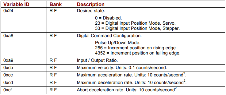
Pulse Up/Down Mode Variables
Pulse Up/Down Mode Example
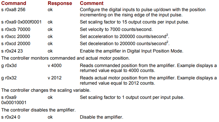
The controller sets the move parameters and then places the amp in the Pulse Up/Down Position Mode, monitors commanded and actual position, and then changes the scaling factor.
3.4.6: Quadrature Mode
In the Quadrature Position Mode, the axis position is commanded by a master encoder with its A and B channels applied to the amplifier’s digital inputs.
The scaling factor sets the ratio of position command, in counts, for each count of the master encoder. The scaling factor is stored in 0xa9 as two 16 bit words. Word 1 stores the numerator or number of position counts. Word 2 stores the denominator or the number of input counts.
Example: To set a ratio of 10 counts of position change for every input count, the ratio would be 10/1. To make sending the data easier, the ratio should be converted to its hex equivalent (0x000a/0x0001). The two words can now be combined and sent to the amplifier by sending the command s r0xa9 0x000a0001.
To invert the direction, the numerator should be set to a negative value.
Example: Changing direction of the previous example would require a ratio of -10/1. Using the 2’s complement method, -10 is represented as 0xfff6 in hex format. The ratio in hex format would now be 0xfff6/0x001. Combining these words, the command to be sent would be s r0xa9 0xfff60001.
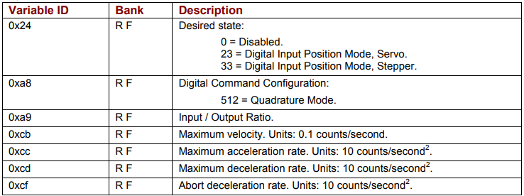
Quadrature Mode Variables
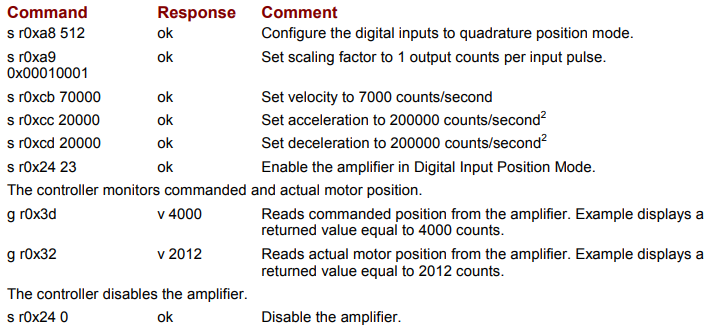
Quadrature Mode Example
The controller sets the move parameters, enables the amplifier in the Quadrature Position Mode, and monitors commanded and actual position.
3.4.7: Homing Mode
Homing sequences can be performed using the t 2 command when the amplifier is in Programmed Position Mode (servo or stepper). In most applications the homing sequence is configured using CME 2 and not changed during operation.
Homing Mode Variables
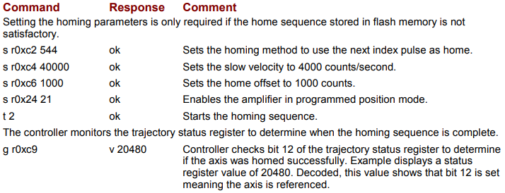
Homing Example
The controller modifies the homing parameters, enables the amplifier in the Programmed Position Mode, initiates a homing sequence and then monitors homing status
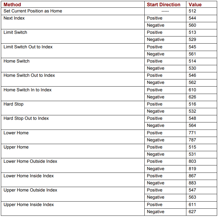
Homing Methods (0xc2)
For a full description of the methods listed below, see Homing Method Descriptions
No comments to display
No comments to display