
4. OPERATION
This chapter describes the variables involved in basic operation of the amplifier. Contents include:
4.1: Setting the Baud Rate
Variable 0x90 (R) controls the amplifier’s serial port baud rate. To change the baud rate, write the new value to 0x90. For instance, to change the value to 19200 send: s r0x90 19200. The amplifier will respond with an “ok” if the command is successful but it will be sent at the new baud rate.
After the carriage return of the s command, no other characters should be sent at 9600 (by default, some programs automatically append a line feed). If more characters are sent at 9600, they may be misinterpreted as a break command and cause the amplifier to change back to 9600 baud. There should also be a delay of 100 mSec minimum before characters at the new baud rate are sent to the amplifier.
When reading variable 0x90, note that the value received may not be the exact value set. This is because the amplifier sets the baud rate as close to the requested baud rate as possible given the internal clock frequencies of the amplifier’s microprocessor.
4.2: Setting Limits and Gains
This section describes the variables used to set control loop limits and gains.
4.2.1: Current Loop Limits and Gains
Current Loop Limits Variables

Current Loop Gains Variables

4.2.2: Velocity Loop Limits and Gains
Velocity Loop Limits Variables

Velocity Loop Gains Variables

4.2.3: Position Loop Gains
Position loop limits are described in Position Mode (p. 29).
Position Loop Gains Variables

4.2.4: Filters
Velocity Loop Filters Variables

Velocity Loops Filters Usage Notes
The velocity loop command and output filters should be set up using CME 2. If it is required that the filters be changed during operation, the following procedure should be used to determine the new filter co-efficients.
1 Set the filter up using CME 2.
1 On the CME 2 Main screen, click V Loop.
2 On the Velocity Loop screen, click Command Filter or Output Filter as desired.
3 On the Filter screen, choose the filter type, set the parameters, click Apply and then click Close.
2 Use the CME 2 ASCII command line tool (Tools->ASCII Command Line) to read the updated variable. For instance, to read the command filter variable:

3 Write program instructions to update the appropriate variable with those values. For instance, to write the command filter variable:

4.3: Monitoring Status
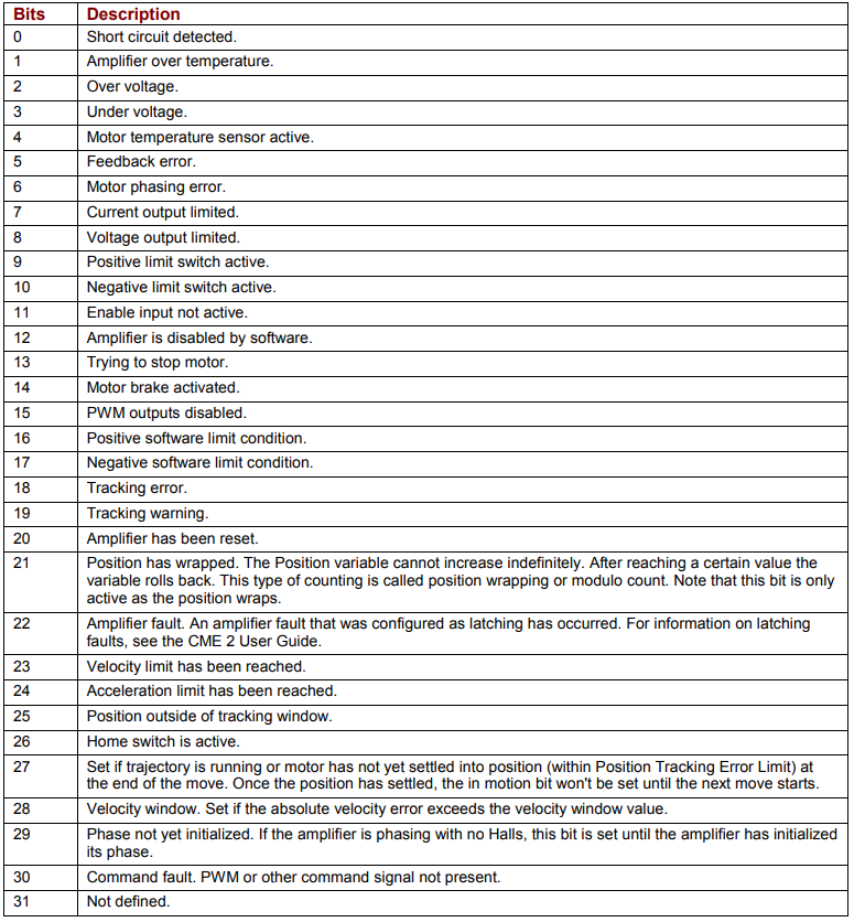
Status Register Variable (0xa0)
The status register variable (0xa0) provides amplifier status information. 0xa0 is read-only, and available in RAM only (not Flash). Bit mapped values described below:
Trajectory Register Variable (0xc9)
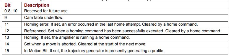
The trajectory register variable (0xc9) provides trajectory generator status information. 0xc9 is read-only, and available in RAM only (not Flash). Bit mapped values described below:
Fault Register Variable (0xa4)
The fault register variable (0xa4) shows latching faults that have occurred. 0xa4 is available in RAM only (not Flash).
Bit mapped values described below:
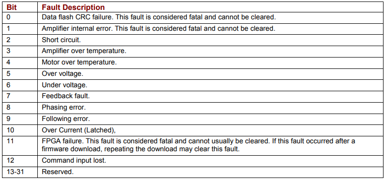
Note that when a latching fault has occurred, bit 22 of the status register (0xa0) is set.
To clear a fault condition, write a 1 to the associated bit of the fault register (0xa4).
4.4: Reading Run Time Variables
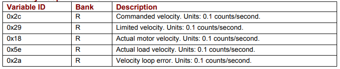
This section describes the variables used to monitor run time conditions.
Current Loop Run Time Variables

Velocity Loop Run Time Variables
Position Loop Run Time Variables

Position Loop Inputs from the Trajectory Generator (Variables)

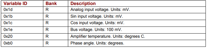
Miscellaneous System Variables
4.5: Reading Digital Inputs
Input States Variable (0xa6)
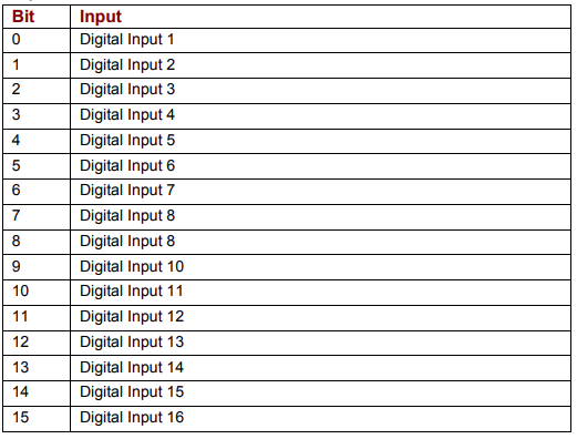
The high/low states of the amplifier’s programmable digital inputs can be read using variable 0xa6. Each bit represents an input number as shown below. If an input is high, the corresponding bit is set to 1. If the input is low, the corresponding bit is set to 0.
For instance, if the value of 0xa6 is 33, the binary equivalent is 100001, showing that IN1 and IN6 are high and the other inputs are low.
0xa6 is read-only, and available in RAM only (not Flash). Bit mapped values described below.
NOTE: The number of programmable digital inputs varies depending on amplifier model. See the amplifier documentation.
4.6: Reading/Setting Digital Outputs
The amplifiers digital outputs can be programmed by CME 2 to reflect the state of any one or more of the amplifier’s event status register bits. The outputs can also be configured so their state can be set by the controller program.
The external controller, through the Output State variable, can set an output inactive or active. The actual level of the output pin however is determined by the Output Configuration variable. This variable sets the actual output pin to be high or low when active. When the amplifier powers up or is reset, all outputs are initially inactive. To ensure that outputs are high, or off, after power up or reset, they should be configured as active low.
Configuring Outputs (0x70 – 0x77)
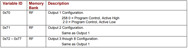
Before a controller program can set an output pin’s active/inactive state, the output must be configured for program control. This is done by setting the appropriate bits in the output’s configuration variable.
The output configuration variables start with 0x70 for Output 1 and run to 0x77 for Output 8, as described below. These variables require two values be sent with Set (s) command.
NOTE: The number of programmable digital inputs varies depending on amplifier mode. See the amplifier documentation
Setting Output States (0xab)
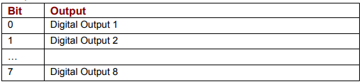
Writing the variable 0xab sets the active/inactive states of digital outputs that have been configured for program control. Each bit represents an output number as shown below. A bit value of 1 corresponds to an active output. A bit value of 0 corresponds to an inactive output.
Writing a 1 or 0 to an output that has not been configured for program control will have no effect on the output.
NOTE: The number of programmable digital outputs varies depending on amplifier model. See the amplifier documentation.
Reading Output States (0xab)
Reading 0xab gets the active/inactive states of all the amplifier’s digital outputs, including those which are not set to program control.
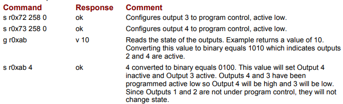
Reading/Setting Output Example
The controller configures 2 outputs for program control, reads the state of the outputs, and then sets an output low.
No comments to display
No comments to display