
APPENDIX D: SERIAL AND MULTI-DROP CONNECTION
This appendix describes how to connect an amplifier for control via the RS-232 serial port.
The serially connected amplifier can also be used as a multi-drop gateway to control other amplifiers linked in a series of CAN bus connections. Contents include:
D.1: Connecting
Instructions for hooking up a single-axis connection and a multi-drop network appear below.
D.1.1: Single-Axis Connections
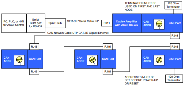
For RS-232 serial bus control of a single axis, set the CAN node address of that axis to zero (0).
Note that if the CAN node address is switched to zero after power-up, the amplifier must be reset or power cycled to make the new address setting take effect.

D.1.2: Multi-Drop Network Connections
For RS-232 serial bus control of multiple axes, set the CAN node address of the serially connected amplifier (gateway) to zero (0). Assign each additional amplifier in the chain a unique CAN node address value between 1 and 127. For information on CAN node address, see the amplifier user guide or data sheet. Verify that all amplifiers are set to the same CAN bit rate. Use 120 termination on the first and last amplifier.
The CAN Status Light and Multi-Drop Connections
When starting amplifiers on a multi-drop CAN loop, it is common to see a green-green-red flash sequence on the CAN Status Indicator LED of the first amplifier to start up. This sequence indicates that the amplifier has not found any other active nodes on the CAN loop. Under normal circumstances, this flash sequence does not indicate a problem, and it will clear after the first few commands are sent to the amplifier.
To avoid seeing this flash sequence, assure that the gateway amplifier starts up first. The CAN status indicator will always be off on node 0.
No comments to display
No comments to display